OO4-ILR-ICARDCFCF Card Reader
Identec Solutions AG
Click to zoom
Application Details
- Equipment Class
- DXT - Part 15 Low Power Transceiver, Rx Verified
- Date of Grant
- Sep 06, 2006
- Application Purpose
- Original Equipment
- Date of Application
- Sep 06, 2006
- Equipment Note
- CF Card Reader
- Frequency Range
- 916.60000000 - 916.60000000
- Company
- Identec Solutions AG
- Country
- Austria
Documents & Files
Document Text
Text extracted from the exhibit documents filed with the FCC. Open a document above to read the original.
Users Manual
i-CARD CF User’s Guide Version 1.2 IDENTEC SOLUTIONS AG Millenniumspark 2 A-6890 Lustenau Austria Tel: +43 (0) 5577 87387 - 0 Fax: +43 (0) 5577 87387 - 15 [email protected] www.identecsolutions.com i-CARD CF – User’s Guide Version 1.2 26.07.2006 Page ii/10 Proprietary Notice This document contains confidential information proprietary to IDENTEC SOLUTIONS and may not be used or disclosed to other parties in whole or in part without prior written authorization from IDENTEC SOLUTIONS. Disclaimer and Limitation of Liability IDENTEC SOLUTIONS AG and its affiliates, subsidiaries, officers, directors, employees and agents provide the information contained in this Manual on an “as-is” basis and do not make any express or implied warranties or representations with respect to such information including, without limitation, warranties as to non-infringement, reliability, fitness for a particular purpose, usefulness, completeness, accuracy or currentness. IDENTEC SOLUTIONS AG shall not in any circumstances be liable to any person for any special, incidental, indirect or consequential damages, including without limitation, damages resulting from use of or reliance on information presented herein, or loss of profits or revenues or costs of replacement goods, even if informed in advance of the possibility of such damages. Trademarks “IDENTEC SOLUTIONS”, “Intelligent Long Range”, “ILR” and the stylized “i” are registered trademarks and “i-Q”, “i-D”, “i-CARD”, “i-PORT”, “i-LINKS”, “Solutions. It’s in our name.”, “Smarten up your assets.” are trademarks of IDENTEC SOLUTIONS, Inc. and/or IDENTEC SOLUTIONS AG. Copyright Notice Copyright © 2006 IDENTEC SOLUTIONS. All rights reserved. No part of this document may be reproduced or transmitted in any form by any means, photographic, electronic, mechanical or otherwise, or used in any information storage and retrieval system, without the prior written permission of IDENTEC SOLUTIONS. i-CARD CF – User’s Guide Version 1.2 26.07.2006 Page iii/10 Radio Frequency Compliance Statement IDENTEC SOLUTIONS AG. is the responsible party for the compliance of the following devices: MODEL: i-PORT i-CARD CF i-D TAGS i-Qxx TAGS FCC ID: O2E-ILR-IPORT OO4-ILR-ICARDCF OO4-ILR-ID2 OO4-ILR-IQ8T or OO4-ILR-IQR CANADA: 35381032062A Pending 3538A 12112 35381021756A or 35381021825 EUROPE: CE 0678(!) CE CE 0678(!) CE 0682(!) The user(s) of these products are cautioned to only use accessories and peripherals approved, in advance, by IDENTEC SOLUTIONS. The use of accessories and peripherals, other than those approved by IDENTEC SOLUTIONS, or unauthorized changes to approved products, may void the compliance of these products and may result in the loss of the user(s) authority to operate the equipment. Operation is subject to the following conditions: (1) these devices may not cause harmful interference, and (2) these devices must accept any interference, including interference that may cause undesired operation of the device. FCC Compliance (i-CARD CF / NA) This equipment has been tested and found to comply with the limits for a Class A digital device, pursuant to Part 15 of the FCC Rules. These limits are designed to provide reasonable protection against harmful interference when the equipment is operated in a commercial environment. This equipment generates, uses, and can radiate radio frequency energy and, if not installed and used in accordance with the instruction manual, may cause harmful interference to radio communication. Operation of this equipment in a residential area is likely to cause harmful interference in which case the user will be required to correct the interference at his/her own expense. Warning: Changes or modifications to this unit not expressly approved by the party responsible for compliance could void the user’s authority to operate the equipment. Industry Canada Compliance (i-CARD CF / NA) This Class A digital apparatus meets all requirements of the Canadian Interference-Causing Equipment Regulations. Cet appareil numérique de la classe A respecte toutes les exigences du Règlement sur le matériel brouilleur du Canada. To reduce potential radio interference to other users, the antenna type and its gain should be so chosen that the equivalent isotropically radiated power (EIRP) is not more than that required for successful communication. The installer of this radio equipment must ensure that the antenna is located or pointed such that it does not emit RF field in excess of Health Canada limits for the general population; consult Safety Code 6, obtainable from Health Canada. i-CARD CF – User’s Guide Version 1.2 26.07.2006 Page iv/10 European Notification according R&TTE Directive (i-CARD CF / EU) This equipment complies to Art. 6.4 of R&TTE Directive (1999/5/EC) and can be used in the following European countries: Austria, Belgium, Denmark, Finland, France, Germany, Greece, Iceland, Italy, Ireland, Luxembourg, Netherlands , Norway, Portugal, Switzerland, Sweden, Spain, United Kingdom, Czech Republic, Cyprus, Estonia, Hungary, Lithuania, Latvia, Malta, Poland, Slovenia. i-CARD CF – User’s Guide Version 1.2 26.07.2006 Page v/10 Table of Contents 1.0 Overview __________________________________________________ 6 1.1 Functionality ________________________________________________________ 6 1.2 Components ________________________________________________________ 6 2.0 Installation ________________________________________________ 7 2.1 Hardware ___________________________________________________________ 7 2.2 Software_________________________________________________ 7 2.2.1 Windows 98/ Windows 2000/Windows ME _____________________________ 8 3.0 Usage ____________________________________________________ 8 4.0 Application program rules_____________________________________ 8 Appendix A: Technical Specifications _______________________________ 10 i-CARD CF – User’s Guide Version 1.2 26.07.2006 Page 6/10 1.0 Overview This guide explains how to install and operate the i-CA…
Text truncated - open the document above for the full version.
Cover Letter(s)
Federal Communications Commission 445 12 th Street SW Washington, DC 20554 USA Request for Confidentiality in accordance with CFR 0.457 and 0.459 04 September 2006 EMCCert DR. RAŠEK - Certification Institute - Boelwiese 5 D-91320 Ebermannstadt RE: Certification Application FCC ID: 004-ILR-ICARDCF Please be advised that the following information is to be held confidential on behalf of Identec Solutions AG: • Schematics • Parts List • Block Diagram • Technical Description The application contains technical information which Identec Solutions AG deems to be trade secrets and proprietary. If made public, the information might be used to the disadvantage of the applicant in the market place. Thank you for your attention to this matter.
External Photos
i-CARD CF, external and internal photos 26.07.2006 i-CARDCF-photos.doc; Autor: Josef Vogel Seite 1/2 1 External photos Front view Rear view Antenna connector
ID Label/Location Info
i-CARD CF – Type Label and Label Placement 26.07.2006 Label_Placement.doc; Autor: Josef Vogel Seite 1/1 The i-CARD CF carries it’s type label on the back side of the CF card. As available space is too small to include the FCC warning statement an additional label is placed on the package.
Internal Photos
i-CARD CF, external and internal photos 26.07.2006 i-CARDCF-photos.doc; Autor: Josef Vogel Seite 2/2 2 Internal photos Internal view, front Internal view, rear side Internal view, CF bus connector
Test Report
Senton GmbH Aeussere Fruehlingstrasse 45 D-94315 Straubing Note: The test data of this report is related only to the individual item which has been tested. This report shall not be reproduced except in full extent without the written approval of the testing laboratory. Test Report No. 55456-060260-2 (Edition 2) Page 1 of 47 Pages Straubing, 04 September 2006 T E S T - R E P O R T No. 55456-060260-2 (Edition 2) for i-CARD CF Q/NA CF Card Reader Applicant: IDENTEC SOLUTIONS AG Test Specifications: FCC Code of Federal Regulations, CFR 47, Part 15, Sections 15.107, 15.109, 15.111(a), 15.205, 15.207, 15.215 and 15.249 Industry Canada Radio Standards Specifications RSS-Gen Issue 1, Sections 7.2.2, 7.2.3 and RSS-210 Issue 6, Sections 2.2, A2.9 (Category I Equipment) Senton GmbH Aeussere Fruehlingstrasse 45 D-94315 Straubing Test Report No. 55456-060260-2 (Edition 2) Page 2 of 47 Pages Table of Contents 1 Description of the Equipment Under Test (EUT)......................................................... 3 2 Administrative Data..................................................................................................... 4 3 Identification of the Test Laboratory............................................................................ 5 4 Summary .................................................................................................................... 6 5 Operation Mode and Configuration of EUT ................................................................. 7 6 Measurement Procedures........................................................................................... 8 6.1 Conducted Output Power ..................................................................................... 8 6.2 Bandwidth Measurements .................................................................................. 10 6.3 Conducted AC Powerline Emission.................................................................... 11 6.4 Radiated Emission in Fully or Semi Anechoic Room .......................................... 13 6.5 Radiated Emission at Open Field Test Site ........................................................ 15 6.6 Antenna Power Conduction Emission of Receivers............................................ 17 7 Photographs Taken During Testing .......................................................................... 19 8 Test Results for Transmitter...................................................................................... 25 8.1 Conducted Output Power ................................................................................... 27 8.2 Occupied Bandwidth........................................................................................... 28 8.3 Bandwidth of the Emission ................................................................................. 33 8.4 Designation of Emissions ................................................................................... 35 8.5 Antenna Requirement......................................................................................... 36 8.6 Restricted Bands of Operation............................................................................ 37 8.7 Conducted Powerline Emission Measurement 150 kHz to 30 MHz ................... 38 8.8 Radiated Emission Measurement 30 MHz to 10 GHz ....................................... 40 8.9 Exposure of Humans to RF Fields...................................................................... 41 9 Test Results for Receiver.......................................................................................... 43 9.1 Radiated Emission Measurement 30 MHz to 5 GHz ......................................... 44 9.2 Antenna Power Conduction Emission of Receivers 9 kHz to 5 GHz ................. 45 10 Referenced Regulations ........................................................................................... 46 11 Charts taken during testing ....................................................................................... 47 Senton GmbH Aeussere Fruehlingstrasse 45 D-94315 Straubing Test Report No. 55456-060260-2 (Edition 2) Page 3 of 47 Pages 1 Description of the Equipment Under Test (EUT) General data of EUT Type designation 1 : i-CARD CF Q/NA Parts 2 : Serial number(s): 06081C0047 Manufacturer: IDENTEC SOLUTIONS AG Type of equipment: CF Card Reader Version: As delivered FCC ID: Additional parts/accessories: Technical data of EUT Application frequency range: 902 - 928 MHz Frequency range: 902 - 928 MHz Operating frequency: 916 MHz Type of modulation: ASK Pulse train: --- Pulse width: --- Number of RF-channels: 1 Channel spacing: --- Designation of emissions 3 : 10K0A1D Type of antenna: Dedicated Antenna Size/length of antenna: 70 mm Connection of antenna: detachable not detachable Type of power supply: DC supply over CF Card Port Specifications for power supply: nominal voltage: 5.0 V minimum voltage: 4.5 V maximum voltage: 5.5 V 1 Type designation of the system if EUT consists of more than one part. 2 Type designations of the parts of the system, if applicable. 3 Also known as "Class of Emission". Senton GmbH Aeussere Fruehlingstrasse 45 D-94315 Straubing Test Report No. 55456-060260-2 (Edition 2) Page 4 of 47 Pages 2 Administrative Data Application details Applicant (full address): IDENTEC SOLUTIONS AG Millenniumspark 2 A-6890 Lustenau Contact person: Mr. Vogel Contract identification: 46600117 Receipt of EUT: 31 March 2006 Date(s) of test: April 2006 Note(s): Report details Report number: 55456-060260-2 Edition: 2 Issue date: 11 July 2006 Senton GmbH Aeussere Fruehlingstrasse 45 D-94315 Straubing Test Report No. 55456-060260-2 (Edition 2) Page 5 of 47 Pages 3 Identification of the Test Laboratory Details of the Test Laboratory Company name: Senton GmbH EMI/EMC Test Center Address: Aeussere Fruehlingstrasse 45 D-94315 Straubing Germany Laboratory accreditation: DAR-Registration No. DAT-P-171/94-02 FCC test site registration number 90926 Industry Canada test site registr…
Text truncated - open the document above for the full version.
Test Setup Photos
Senton GmbH Aeussere Fruehlingstrasse 45 D-94315 Straubing Test Report No. 55456-060260-2 (Edition 2) Page 20 of 47 Pages Test setup for conducted AC powerline emission measurement Senton GmbH Aeussere Fruehlingstrasse 45 D-94315 Straubing Test Report No. 55456-060260-2 (Edition 2) Page 21 of 47 Pages Test setup for radiated emission measurement (fully anechoic room) Senton GmbH Aeussere Fruehlingstrasse 45 D-94315 Straubing Test Report No. 55456-060260-2 (Edition 2) Page 22 of 47 Pages Test setup for radiated emission measurement (open field test site) Senton GmbH Aeussere Fruehlingstrasse 45 D-94315 Straubing Test Report No. 55456-060260-2 (Edition 2) Page 23 of 47 Pages Test setup for radiated emission measurement (open field test site) - continued - Senton GmbH Aeussere Fruehlingstrasse 45 D-94315 Straubing Test Report No. 55456-060260-2 (Edition 2) Page 24 of 47 Pages Test setup for antenna power conduction emission of receivers measurement
Contact Information
Applicant
Karl Heinz Feierle(VP Hardware Development)
Test Firm
TUV SUD Product Service GmbH PS-EMC-STRRainer Heller
Technical Specifications
| # | Rule Parts | Frequency Range | Power Output |
|---|---|---|---|
| 1 | 15C | 916.6 MHz - 916.6 MHz | - |
Other Applications from Identec Solutions AG
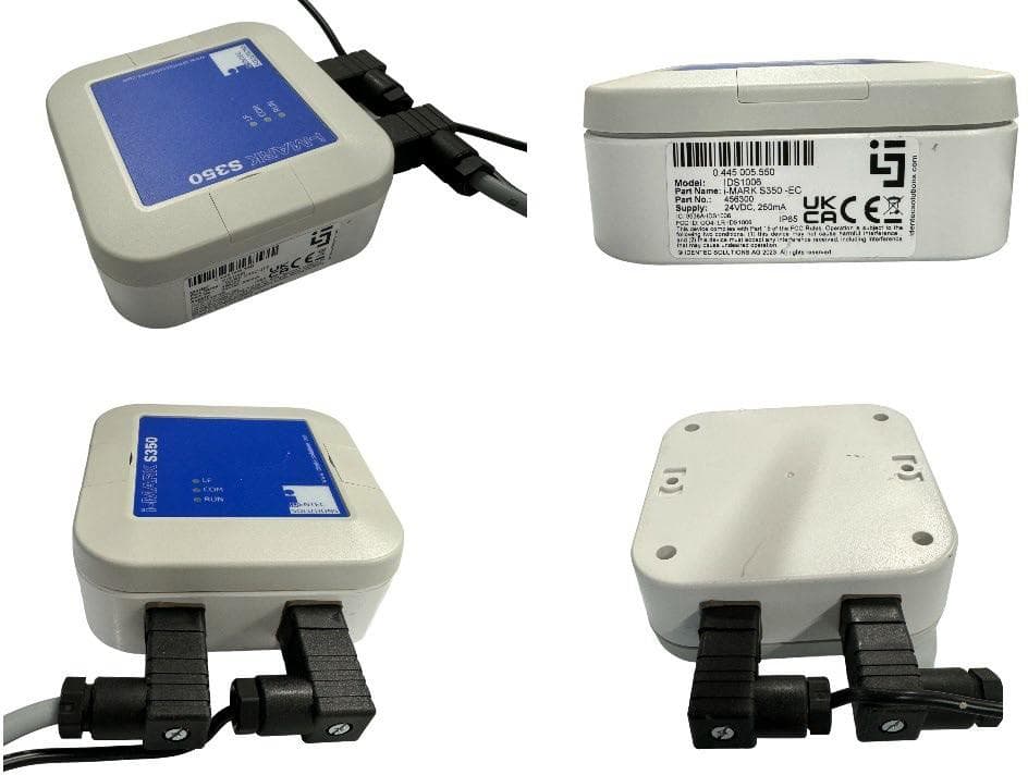
OO4-IDS1014
Sep 26, 2024iMARK EC and iMARK IC
Equipment Class
DXX - Part 15 Low Power Communication Device Transmitter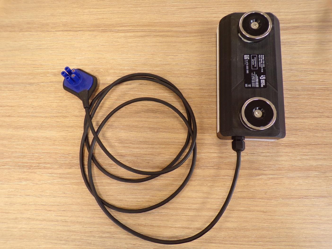
OO4-IDS1009
Mar 24, 2024iQ350 RNB tag
Equipment Class
DXX - Part 15 Low Power Communication Device Transmitter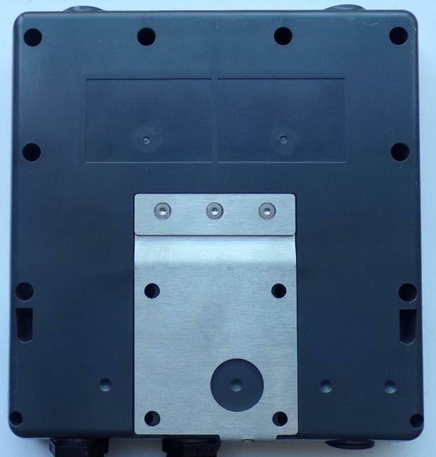
OO4-IDS1001
Dec 17, 2020iPOINT Si UHF / NFC / LF reader
Equipment Class
DXX - Part 15 Low Power Communication Device Transmitter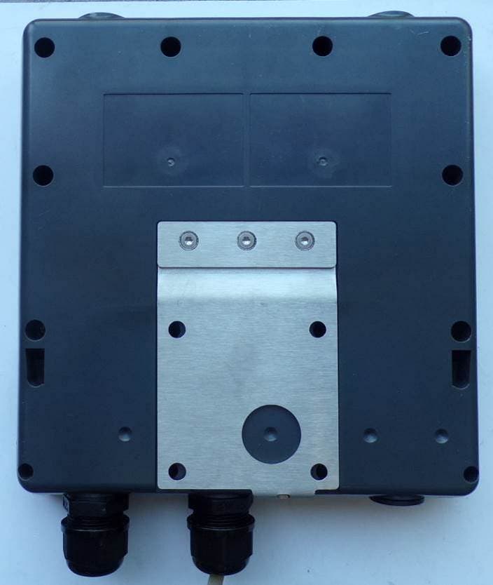
OO4-IDS1002
Oct 08, 2020iPoint X (ATEX) UHF / NFC / LF reader
Equipment Class
DXX - Part 15 Low Power Communication Device Transmitter
OO4-IDS1000
May 03, 2020iQ355 (X)P Personal Tag
Equipment Class
DXX - Part 15 Low Power Communication Device Transmitter