OO4-ILR-IQRIQR-D/E
Identec Solutions AG
Click to zoom
Application Details
- Equipment Class
- DSR - Part 15 Remote Control/Security Device Transceiver
- Date of Grant
- Dec 17, 2001
- Application Purpose
- Original Equipment
- Date of Application
- May 30, 2000
- Equipment Note
- IQR-D/E
- Frequency Range
- 868.00000000 - 868.60000000
- Company
- Identec Solutions AG
- Country
- Austria
Documents & Files
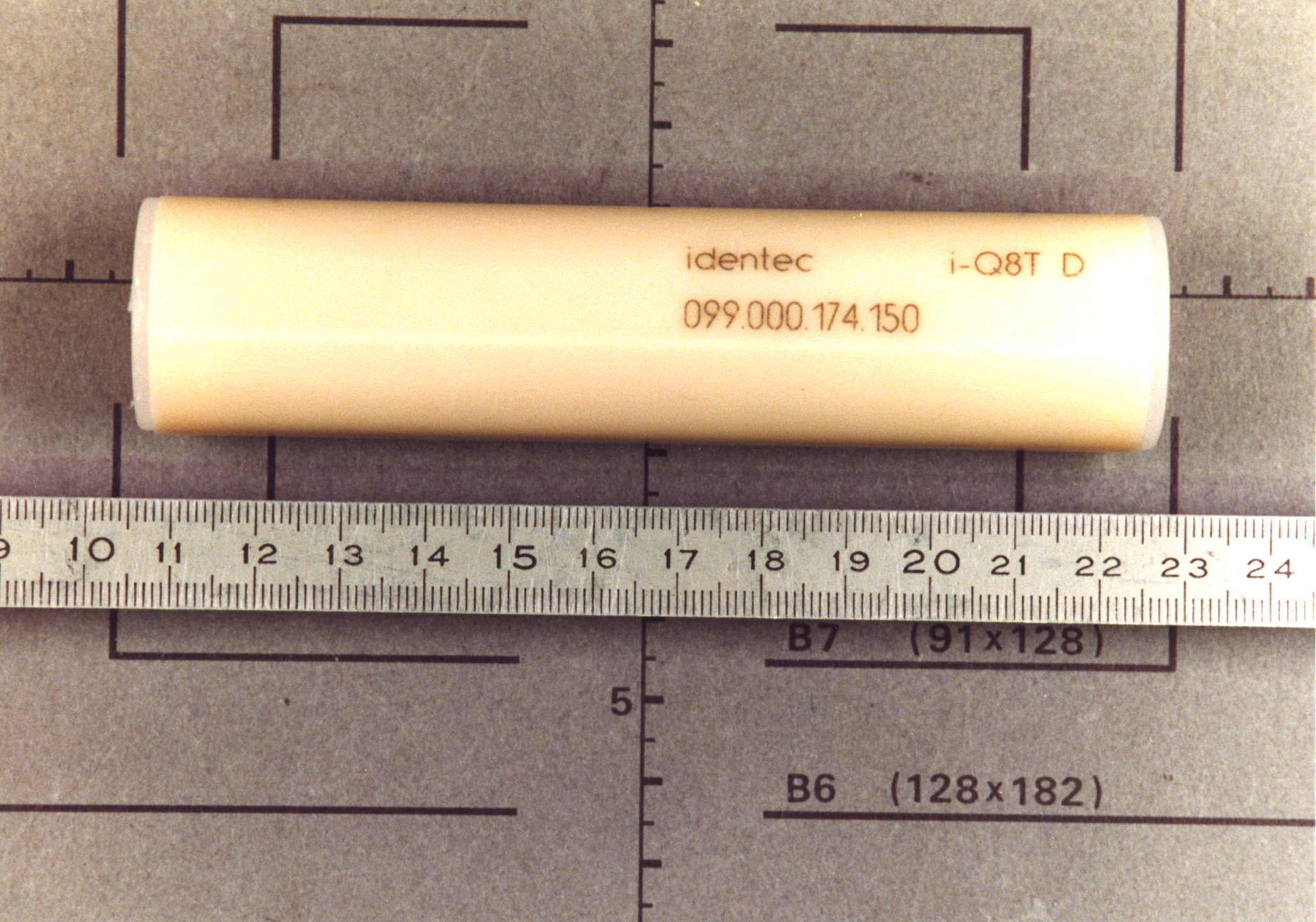
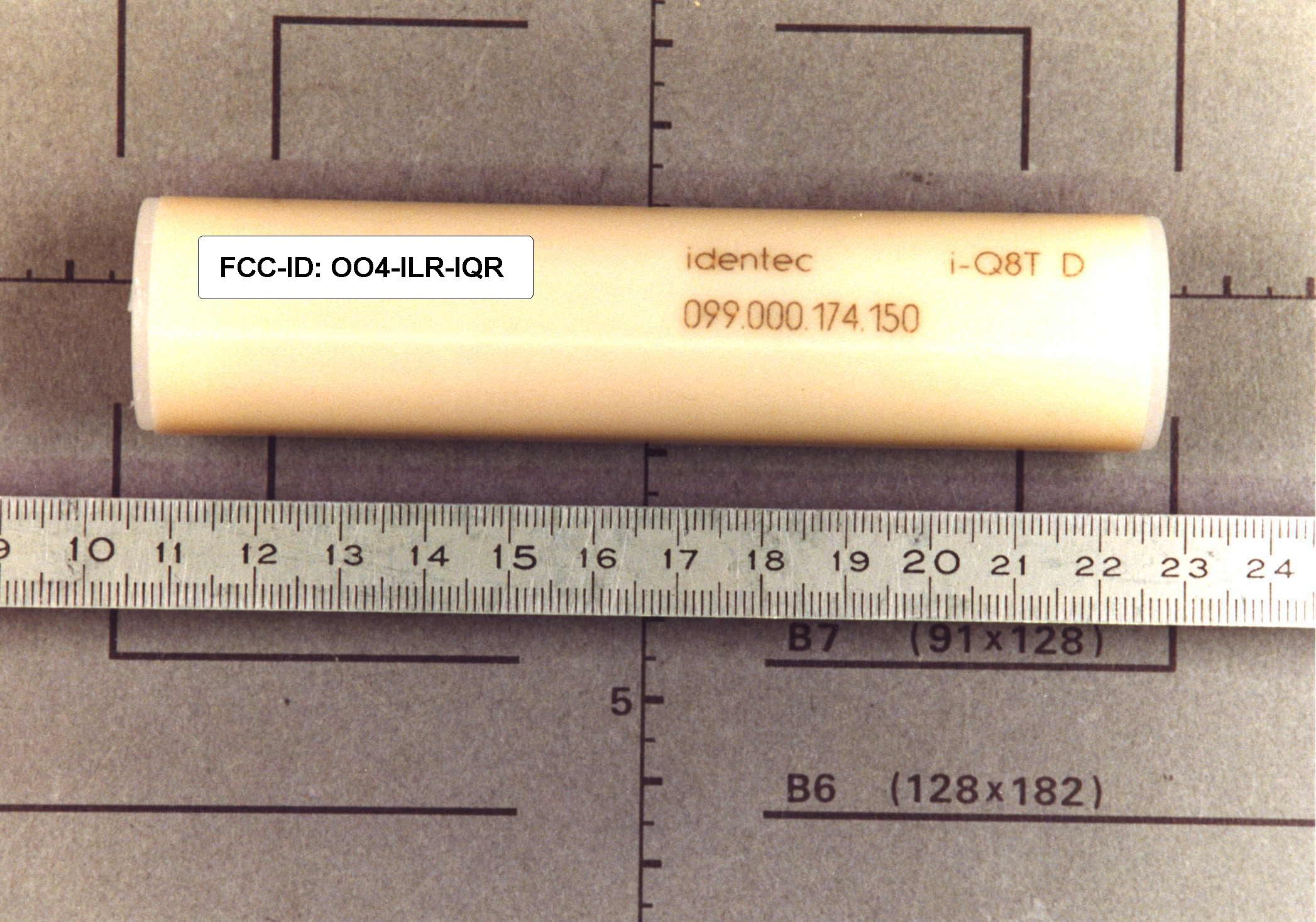
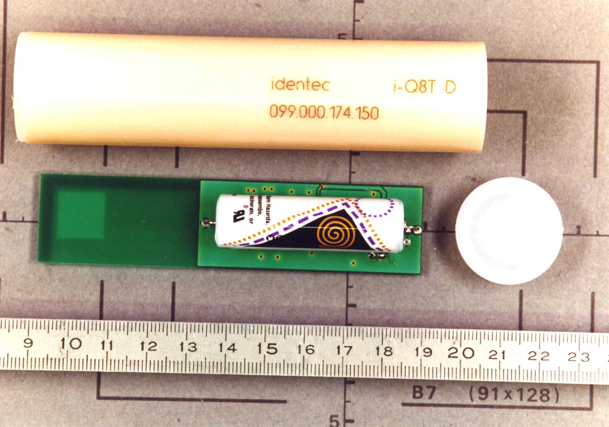
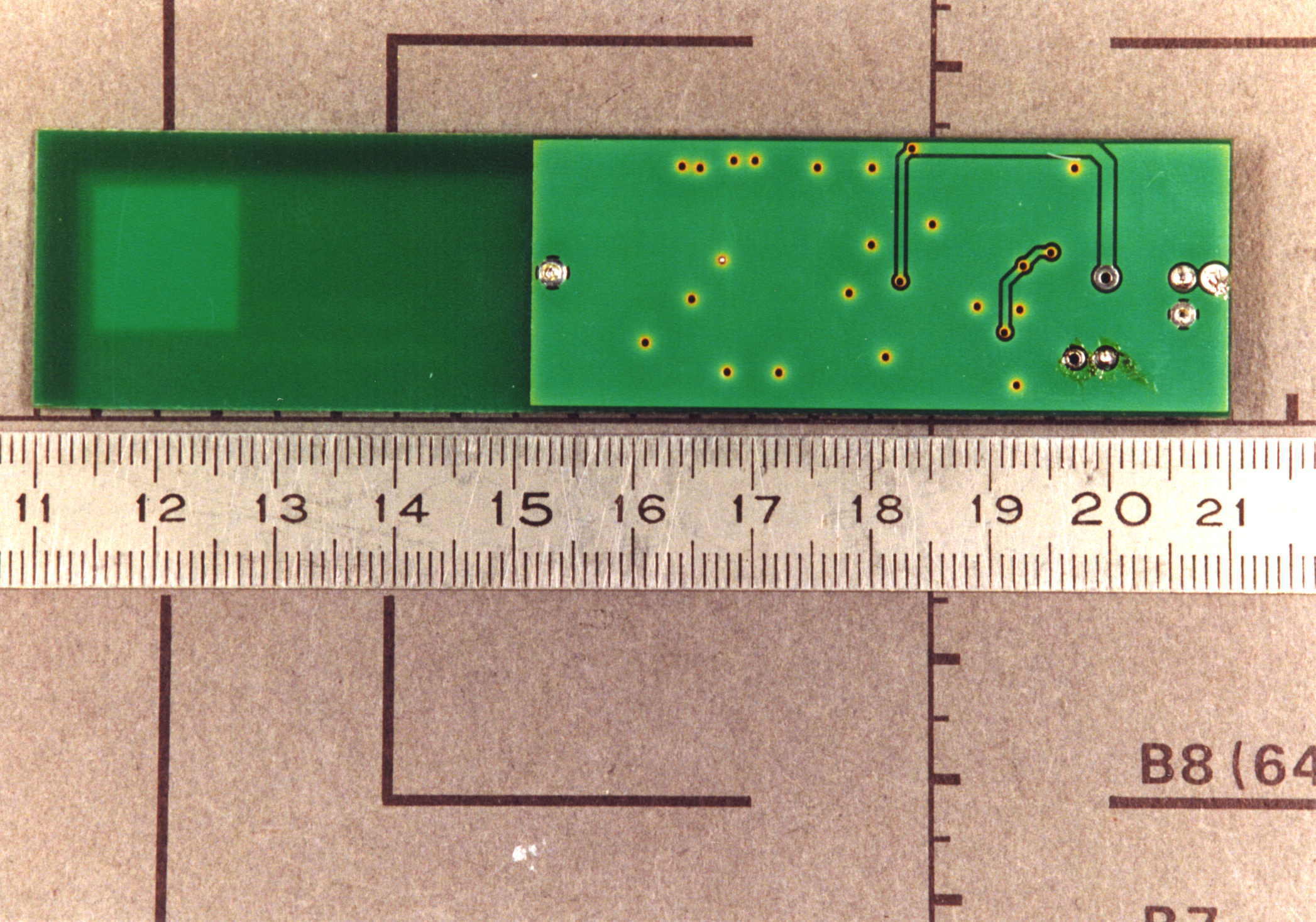
Document Text
Text extracted from the exhibit documents filed with the FCC. Open a document above to read the original.
Schematics
IMPORTANT NOTE: According to manufacturer equipment model IQR-D/E is identical to the tested version IQ8T-D/E (no difference in hardware) except for with IQR-D/E there is no data transmission after data carrier is identified as required by CFR47 Part 15 Section 15.231(a)
Test Report
EMV-Prüfzentrum EMI/EMC-Testcenter Page 1 of 47 Pages Straubing, August 20, 1999 T E S T - R E P O R T No. 55411-90496-2 for IQ8T-D/E Transceiver (868.35 MHz) Applicant:Identec Solutions GmbH & Co Purpose of testing:To show compliance with FCC Code of Federal Regulations, Part 15 Subpart C, Section §15.231 Note: The test data of this report relate only to the individual item which has been tested. This report shall not be reproduced except in full extent without the written approval of the testing laboratory. EMV-Prüfzentrum EMI/EMC-Testcenter FCC-ID: OO4-ILR-IQRTest Report No. 55411-90496-2 Page 2 of 47 Pages Table of Contents 1. Administrative Data....................................................................................3 2. Summary of Test Results...........................................................................4 3. Operation Mode of EUT.............................................................................5 4. Configuration of EUT and Peripheral Devices...........................................6 5. Measuring Methods...................................................................................7 5.1. Bandwidth of Emission(FCC §15.231.c)................................................7 5.2. Radiated Emission 30 MHz - 1 GHz (FCC §15.205.a,b, §15.209, §15.231.b)..............................................................................8 5.3. Radiated Emission 1 GHz - 10 GHz (FCC §15.205.a,b, §15.209, §15.231.b)............................................................................10 6. Equipment List.........................................................................................12 7. Photographs Taken During Testing.........................................................14 8. List of Measurements...............................................................................18 8.1. List of Measurements According To FCC Part 15 Subpart C..............19 9. Referenced Regulations..........................................................................20 10. Test Results.............................................................................................21 EMV-Prüfzentrum EMI/EMC-Testcenter FCC-ID: OO4-ILR-IQRTest Report No. 55411-90496-2 Page 3 of 47 Pages 1.Administrative Data Equipment Under Test (EUT):IQ8T-D/E Serial number:0099.000.174.150 Type of equipment:Transceiver (868.35 MHz) Parts/accessories:--- FCC-ID:OO4-ILR-IQR Applicant:Identec Solutions GmbH & Co (full address)Montafonerstraße 8 A-6780 Schruns Contract identification:--- Contact person:Mr. Wilhelm Gantner Manufacturer:Identec Solutions GmbH & Co Receipt of EUT:August 09, 1999 Date of test:August 09, 1999 Note:During testing EUT was called "IQ8T-D/E" Test Laboratory:Senton GmbH EMI/EMC Test Center (full address):Aeussere Fruehlingstrasse 45 D-94315 Straubing Germany Contact person:Mr. Johann Roidt FCC file number:31040/SIT 1300F2 Responsible for testing:Rupert Kohlhäufl Responsible for test report:Rupert Kohlhäufl EMV-Prüfzentrum EMI/EMC-Testcenter FCC-ID: OO4-ILR-IQRTest Report No. 55411-90496-2 Page 4 of 47 Pages 2.Summary of Test Results The tested sample complies with the requirements set forth in the Code of Regulations Part 15 Subpart C, Section §15.231 (intentional radiators) of the Federal Communication Commission (FCC). Johann RoidtRupert Kohlhäufl Technical ManagerTest Engineer EMV-Prüfzentrum EMI/EMC-Testcenter FCC-ID: OO4-ILR-IQRTest Report No. 55411-90496-2 Page 5 of 47 Pages 3.Operation Mode of EUT EUT is transmitting continuously with modulation, supplied by battery (3.6 V DC) EMV-Prüfzentrum EMI/EMC-Testcenter FCC-ID: OO4-ILR-IQRTest Report No. 55411-90496-2 Page 6 of 47 Pages 4.Configuration of EUT and Peripheral Devices Configuration of EUT EUT is configured as stand-alone device Configuration of cables of EUT Not applicable Configuration of peripheral devices connected to EUT Not applicable EMV-Prüfzentrum EMI/EMC-Testcenter FCC-ID: OO4-ILR-IQRTest Report No. 55411-90496-2 Page 7 of 47 Pages 5.Measuring Methods 5.1.Bandwidth of Emission(FCC §15.231.c) The Bandwidth of Emission is measured with a spectrum analyzer connected to measuring antenna (radiated measurement) or test fixture while EUT is operating in transmit mode with modulation at the appropriate center frequency. To increase received signal level distance to EUT is reduced (appropriate level offset is included). The spectrum analyzer was set to: RBW = 10 kHz, VBW = 10 kHz, span = 2 MHz, sweep = 60 ms See figure 1 for the measurement setup. Test equipment used (see quipment list for details): 02, 55, 67 5 2 1 4 3 Figure 1: Measurement setup for bandwidth of emission test 1Transmitter (EUT)3Test fixture 2Wooden table4Test cable 5Spectrum analyzer EMV-Prüfzentrum EMI/EMC-Testcenter FCC-ID: OO4-ILR-IQRTest Report No. 55411-90496-2 Page 8 of 47 Pages 5.2.Radiated Emission 30 MHz - 1 GHz (FCC §15.205.a,b, §15.209, §15.231.b) Radiated emissions are measured over the frequency range from 30 MHz to 1 GHz. The bandwidth of the EMI-receiver is set to 120 kHz and the detector- function is set to CISPR quasi-peak. The test setup is made in accordance with ANSI C63.4-1992. Measurements are made in both the horizontal and vertical planes of polarization. Preliminary scans are taken in a semi-anechoic room using a spectrum analyzer with the detector function set to peak. Hand-held or body-worn devices are rotated through three orthogonal axes to determine which attitude and configuration produces the highest emission relative to the limit and therefore shall be used for final testing. All tests are performed at a test-distance of 3 meters. For final testing an open-area test-site is used. During the tests the EUT is rotated all around and the receiving-antenna is raised and lowered from 1 meter to 4 meters to find the maximum levels of emissions. The cables and equipment is placed and moved within the range of position likely to find their maximum emissions. See figure 2 for the measurement setup. Test equ…
Text truncated - open the document above for the full version.
Contact Information
Applicant
Karl Heinz Feierle(VP Hardware Development)
Technical Contact
Senton GmbHJohann Roidt
[email protected]+49 9421 5522
Aeussere Fruehlingstrasse 45 · D-94315 Straubing · Germany
Non-Technical Contact
Senton GmbHJohann Roidt
[email protected]+49 9421 5522
Test Firm
TUV SUD Product Service GmbH PS-EMC-STRRainer Heller
Technical Specifications
| # | Rule Parts | Frequency Range | Power Output | Tolerance |
|---|---|---|---|---|
| 1 | 15C | 868 MHz - 868.6 MHz | - | % |
Other Applications from Identec Solutions AG
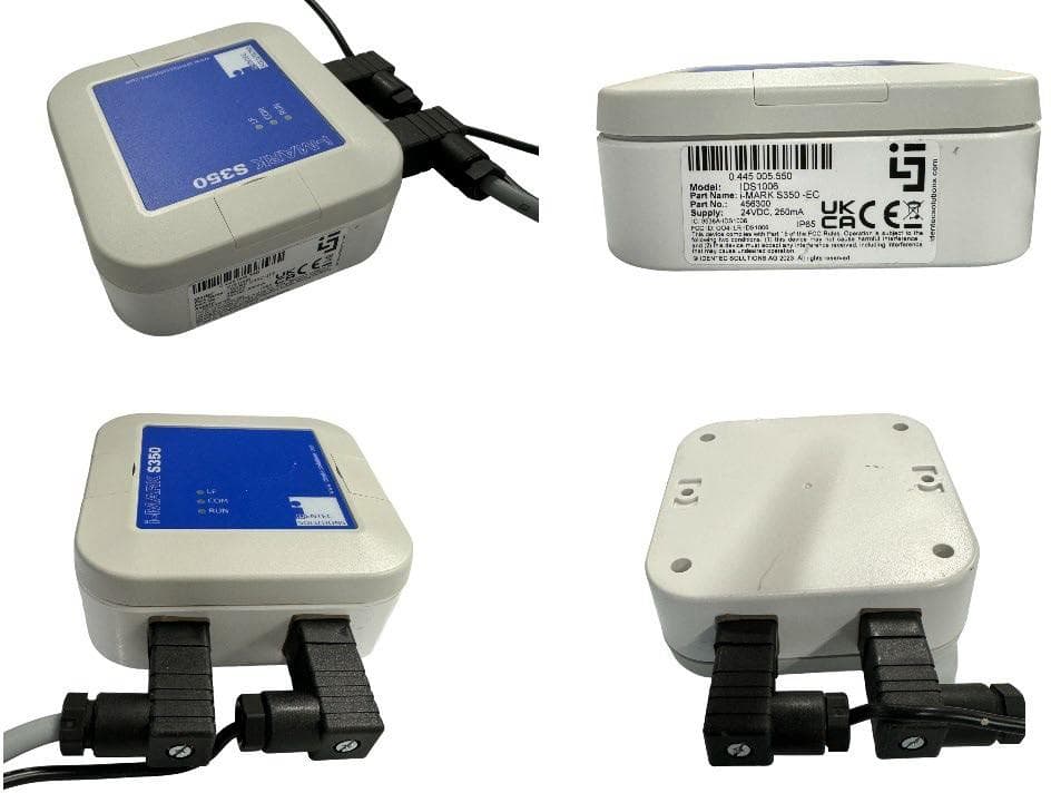
OO4-IDS1014
Sep 26, 2024iMARK EC and iMARK IC
Equipment Class
DXX - Part 15 Low Power Communication Device Transmitter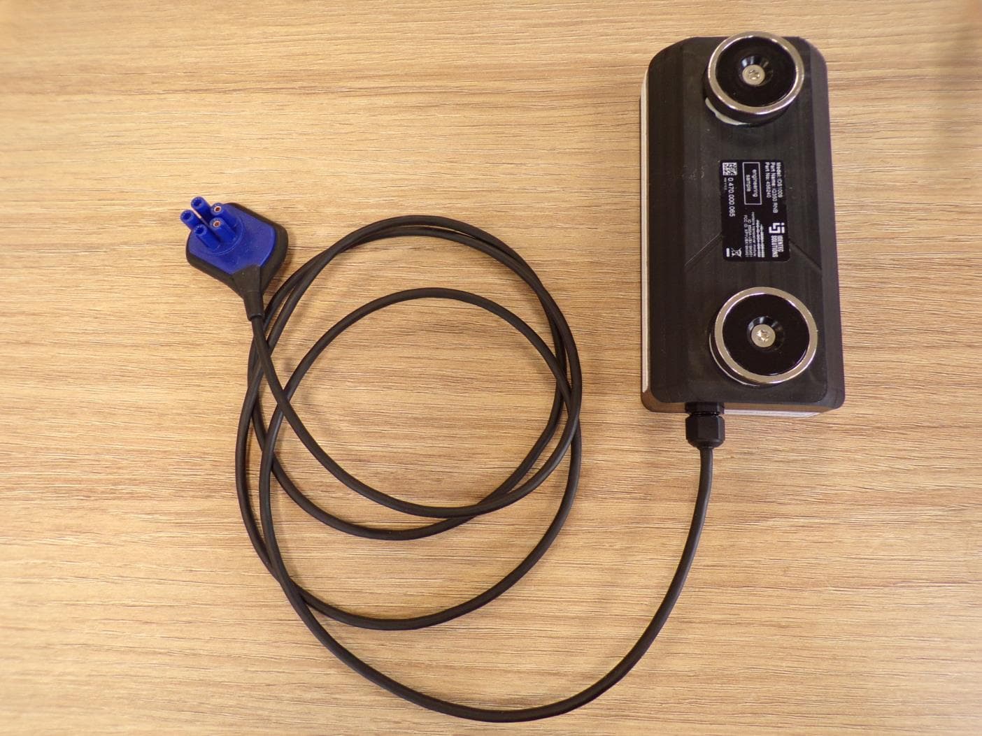
OO4-IDS1009
Mar 24, 2024iQ350 RNB tag
Equipment Class
DXX - Part 15 Low Power Communication Device Transmitter
OO4-IDS1001
Dec 17, 2020iPOINT Si UHF / NFC / LF reader
Equipment Class
DXX - Part 15 Low Power Communication Device Transmitter
OO4-IDS1002
Oct 08, 2020iPoint X (ATEX) UHF / NFC / LF reader
Equipment Class
DXX - Part 15 Low Power Communication Device Transmitter
OO4-IDS1000
May 03, 2020iQ355 (X)P Personal Tag
Equipment Class
DXX - Part 15 Low Power Communication Device Transmitter