OO9P714GAMING MOUSE
G.Tech Technology Ltd.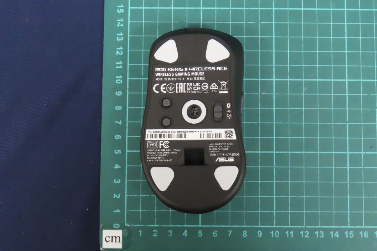
Click to zoom
Application Details
- Equipment Class
- DTS - Digital Transmission System
- Date of Grant
- May 09, 2024
- Application Purpose
- Original Equipment
- Date of Application
- May 08, 2024
- Equipment Note
- GAMING MOUSE
- Frequency Range
- 2402.00000000 - 2480.00000000
- Company
- G.Tech Technology Ltd.
- Country
- China
Documents & Files
Document Text
Text extracted from the exhibit documents filed with the FCC. Open a document above to read the original.
Users Manual
PT:BR NL CS DE RU IT FI ES TR ZH EN HU FR ZH:SC Mouse features / 滑鼠功能 / 鼠標功能 Package Contents Q23002 / First Edition / January 2024 Quick Start Guide 快速使用指南(繁體中文) 快速使用指南(簡體中文) クイックスタートガイド (JP) 간단사용설명서 (KO) Guide de démarrage rapide (FR) Schnellstartanleitung (DE) Guida rapida (IT) Guia de Início Rápido (PT:BR) Краткое руководство (RU) Guía de inicio rápido (ES) Beknopte handleiding (NL) Hızlı Başlangıç Kılavuzu (TR) Стисле керівництво для початку експлуатації (UA) Przewodnik szybkiego startu (PL) Rychlý průvodce (CS) Ghid de pornire rapidă (RO) Gyors üzembe helyezési útmutató (HU) Snabbstartshandbok (SV) Pikaopas (FI) Hurtigstartveiledning (NO) Stručný návod na používanie (SK) (AR)دليل التشغيل السريع )HBמדריך להתחלה מהירה ( Profile switching ProfileHot KeyLighting effect Profile 1 + (Cycles through Profiles 1~5) Color Cycle Profile 2Breathing (purple) Profile 3Static (blue) Profile 4Breathing (green) Profile 5Reactive (yellow) Specifications* ResolutionDPI 1DPI 2DPI 3 (Default)DPI 4 100 DPI to 42000 DPI400 DPI800 DPI1600 DPI3200 DPI * You may customize the DPI settings for DPI 1-4 through Armoury Crate or the DPI On-The-Scroll tuning function. * We recommend using the wireless dongle extender when using the mouse in 2.4GHz mode. 我們建議當您在使用鍵盤的 RF 2.4GHz 無線模式時,使用無線接收器延長器。 我們建議當您在使用鍵盤的 RF 2.4GHz 無線模式時,使用無線接收器延長器。 ** Only use the wireless dongle extender for the wireless dongle. 無線接收器延長器僅可用於連接無線接收器。 無線接收器延長器僅可用於連接無線接收器。 *** Remove the pre-installed mouse feet before installing the bundled mouse feet. Remove the pre-installed mouse feet before installing the bundled mouse feet. Remove the pre-installed mouse feet before installing the bundled mouse feet. Left-click button / 左鍵 / 左鍵 USB Type-C® connector / USB Type-C® 連接埠 / USB Type-C® 接口 Scroll wheel / 滾輪 / 滾輪 DPI button / DPI 按鈕 / DPI 按鈕 Right-click button / 右鍵 / 右鍵 Pairing button / 配對按鈕 / 配對按鈕 Forward button / 向前按鈕 / 向前按鈕 USB dongle / USB 無線訊號接收器 / USB 無線信號接 收器 Backward button / 向後按鈕 / 向後按鈕 Optical sensor / 光學感測器 / 光學感應器 Mouse feet / 滑鼠腳墊 / 鼠標腳墊 Connection mode switch / 連線模式切換開關 / 連接 模式切換開關 Onboard settings adjustment DescriptionKey CombinationLighting effect Hardware Reset Hold Left-click button + Right-click button + Scroll wheel + DPI button for 3 seconds The Scroll LED will blink red once the key combination is held down until the reset is complete. The scroll LED will blink green once the reset is complete. Polling rate level switch Pairing button + Backward button Cycles through the following polling rates: 125 (red) / 250 (purple) / 500 (blue, BT not supported) / 1000 Hz (green, BT not supported) / 2000 Hz (yellow, with polling booster, BT not supported) / 4000 Hz (blue-green, with polling booster, BT not supported) / 8000 Hz (white, with polling booster, BT not supported) Sensor Lift-off-distance level switch Pairing button + Forward button Cycles through the following lift-off-distances: Low (red, default) / High (purple) Setting up your gaming mouse as a Bluetooth® wireless mouse Set the connection switch to the Bluetooth® mode. Updating the firmware and customization 1. Connect your gaming mouse to your computer using the bundled cable, then connect the USB dongle to a USB port. 2. Download and install the Armoury Crate software from https://rog.asus.com 3. Follow the software instructions to update your gaming mouse and dongle’s firmware. 4. Customize your gaming mouse using Armoury Crate. Connecting your gaming mouse Setting up your gaming mouse as a wired mouse Connect the bundled USB Type-C® to Type-A cable to your gaming mouse and a USB port on your computer Setting up your gaming mouse as a RF wireless mouse 1. Connect the USB dongle to a USB port on your computer. 2. Set the connection switch to the RF 2.4G Wireless mode. Pairing Bluetooth® mode to additional host devices (max. 3) 1. Set the connection switch to the Bluetooth® mode. 2. Press and hold the Pairing button for 3 seconds until the LED on your gaming mouse start to blink blue. Once your gaming mouse has been successfully paired, the LED indicator on your gaming mouse will light up blue for 3 seconds. Using the DPI On-The-Scroll tuning function The DPI On-The-Scroll tuning function allows you to customize the DPI of your gaming mouse without using Armoury Crate. 1. Press and hold the DPI button for 3 seconds until the LED on your gaming mouse light up. 2. Scroll the scroll wheel forwards or backwards to adjust the DPI. The LED color hue on your mouse will differ depending on the DPI adjustment. 3. Press the DPI button once you have finished customizing the DPI value to save the changes made. Setting up your gaming mouse as a Bluetooth® wireless mouse Set the connection switch to the Bluetooth® mode. Updating the firmware and customization 1. Connect your gaming mouse to your computer using the bundled cable, then connect the USB dongle to a USB port. 2. Download and install the Armoury Crate software from https://rog.asus.com 3. Follow the software instructions to update your gaming mouse and dongle’s firmware. 4. Customize your gaming mouse using Armoury Crate. Connecting your gaming mouse Setting up your gaming mouse as a wired mouse Connect the bundled USB Type-C® to Type-A cable to your gaming mouse and a USB port on your computer Setting up your gaming mouse as a RF wireless mouse 1. Connect the USB dongle to a USB port on your computer. 2. Set the connection switch to the RF 2.4G Wireless mode. Pairing Bluetooth® mode to additional host devices (max. 3) 1. Set the connection switch to the Bluetooth® mode. 2. Press and hold the Pairing button for 3 seconds until the LED on your gaming mouse start to blink blue. Once your gaming mouse has been successfully paired, the LED indicator on your gaming mouse will light up blue for 3 seconds. Using the DPI On-The-Scroll tuning function The DPI On-The-Scroll tuning function allows you to customize the DPI of your gaming mouse without using Armoury Crate. 1. Press and hold the DPI button for 3 seconds until the LED on …
Text truncated - open the document above for the full version.
External Photos
Report No.: 2410097R-Product Photos Page: 1 of 20 (1) EUT Photo (2) EUT Photo Report No.: 2410097R-Product Photos Page: 2 of 20 (3) EUT Photo (4) EUT Photo Report No.: 2410097R-Product Photos Page: 3 of 20 (5) EUT Photo (6) EUT Photo Report No.: 2410097R-Product Photos Page: 4 of 20 (7) EUT Photo (8) EUT Photo Report No.: 2410097R-Product Photos Page: 5 of 20 (9) EUT Photo (10) EUT Photo Report No.: 2410097R-Product Photos Page: 6 of 20 (11) EUT Photo (12) EUT Photo
ID Label/Location Info
Label Here
ID Label/Location Info
珠海市智迪科技股份有限公司 G.TECH TECHNOLOGY LTD. 物料名称Descripti on: 比例Drawing scale: 设计 陈怡良 衷安春 Designer: 审核Reviewed by: 批准Approved by: 日期Date: 日期Date: 日期Date: MM±0.3 1.0 1:1 物料品号P/N : 单位Unit:允许公差Tolerance: 版本Version: 罗丽琼 2024.01.14 2024.01.14 2024.01.14 ASUS/P714 鼠标底贴纸 黑色款 技术要求: 1. 材质:100g合成纸+哑膜 2. 无矿物油油墨印刷 3. 过ASUS公司高低温测试 4. 卷装来料 6 4. 63 WIRELESS GAMING MOUSE MODEL/型號/型号: P714 品名: 電競滑鼠 R-R-MSQ-P714 Made in China /中國製造 RATING/規格/规格:5VDC 500mA PRODUCT NAME:GAMING MOUSE FCC ID: OO9P714 IC: 20090-P714 CAN ICES-003(B)/NMB-003 R-NZ 60.92 6 ROG KERIS II ACE xxx-xxxxxx CCAHXXXXXXXXXCMIIT ID:XXXXXXXXXXX Support WIRELESS GAMING MOUSE MODEL/型號/型号: P714 品名: 電競滑鼠 R-R-MSQ-P714 Made in China /中國製造 RATING/規格/规格:5VDC 500mA PRODUCT NAME:GAMING MOUSE FCC ID: OO9P714 IC: 20090-P714 CAN ICES-003(B)/NMB-003 R-NZ ROG KERIS II ACE xxx-xxxxxx CCAHXXXXXXXXXCMIIT ID:XXXXXXXXXXX Support WIRELESS GAMING MOUSE MODEL/型號/型号: P714 品名: 電競滑鼠 R-R-MSQ-P714 Made in China /中國製造 RATING/規格/规格:5VDC 500mA PRODUCT NAME:GAMING MOUSE FCC ID: OO9P714 IC: 20090-P714 CAN ICES-003(B)/NMB-003 R-NZ ROG KERIS II ACE xxx-xxxxxx CCAHXXXXXXXXXCMIIT ID:XXXXXXXXXXX Support
Internal Photos
Report No.: 2410097R-Product Photos Page: 7 of 18 (13) EUT Photo (14) EUT Photo Report No.: 2410097R-Product Photos Page: 8 of 18 (15) EUT Photo (16) EUT Photo Report No.: 2410097R-Product Photos Page: 9 of 18 (17) EUT Photo (18) EUT Photo Report No.: 2410097R-Product Photos Page: 10 of 18 (19) EUT Photo (20) EUT Photo Report No.: 2410097R-Product Photos Page: 11 of 18 (21) EUT Photo (22) EUT Photo Report No.: 2410097R-Product Photos Page: 12 of 18 (23) EUT Photo (24) EUT Photo Report No.: 2410097R-Product Photos Page: 13 of 18 (25) EUT Photo (26) EUT Photo RF Module RF Antenna Report No.: 2410097R-Product Photos Page: 14 of 18 (27) EUT Photo (28) EUT Photo Report No.: 2410097R-Product Photos Page: 15 of 18 (29) EUT Photo (30) EUT Photo Report No.: 2410097R-Product Photos Page: 16 of 18 (31) EUT Photo (32) EUT Photo Report No.: 2410097R-Product Photos Page: 17 of 18 (33) EUT Photo (34) EUT Photo Report No.: 2410097R-Product Photos Page: 18 of 18 (35) EUT Photo
RF Exposure Info
Report No.: 2410097R-SAUSV01S-A Page: 1 of 26 Test report No.: 2410097R-SAUSV01S-A SAR Test Report Product Name GAMING MOUSE Trademark ASUS Model and /or type reference P714 Applicant ́s name / address G.Tech Technology Ltd. No.8, Jinyuan 1st Road, Tangjiawan Town High-tech Zone, Zhuhai, 519085, China Manufacturer ́s name ASUSTeK COMPUTER INC. FCC ID OO9P714 Applicable Standard IEEE 1528-2013 KDB 447498 D01 v06 KDB 865664 D01 v01r04 Test Result Max. SAR Measurement (1g) 2.4 GHz: 0.114 W/kg Verdict Summary IN COMPLIANCE Documented By (Senior Project Specialist / Joanne Lin) Te s t e d B y (Senior Engineer / Luke Cheng) Approved By (Assistant Manager / San Lin) Date of Receipt 2024/01/03 Date of Issue 2024/01/25 Report Version V1.0 Report No.: 2410097R-SAUSV01S-A Page: 2 of 26 INDEX Page 1. General Information ........................................................................................................ 5 1.1 EUT Description ................................................................................................. 5 1.2 Antenna List ....................................................................................................... 5 1.3 SAR Test Exclusion Calculation ......................................................................... 6 1.4 Test Environment ................................................................................................ 7 1.5 Measurement procedures................................................................................... 8 2. SAR Measurement System ............................................................................................. 9 2.1 DASY System Description .................................................................................. 9 2.2 Area Scans ....................................................................................................... 10 2.3 DASY E-Field Probe ......................................................................................... 11 2.4 DATA Acquisition Electronics (DAE) and Measurement Server ........................ 12 2.5 Robot ................................................................................................................ 13 2.6 Device Holder ................................................................................................... 13 2.7 Phantom ........................................................................................................... 14 3. Tissue Simulating Liquid .............................................................................................. 15 3.1 The composition of the tissue simulating liquid ................................................ 15 3.2 Tissue Calibration Result .................................................................................. 15 3.3 Tissue Dielectric Parameters for Phantoms ..................................................... 16 4. Measurement Procedure ............................................................................................... 17 4.1 SAR System Check .......................................................................................... 17 4.2 SAR Measurement Procedure .......................................................................... 18 5. RF Exposure Limits ....................................................................................................... 19 6. Test Equipment List ...................................................................................................... 20 7. Measurement Uncertainty ............................................................................................. 22 8. Conducted Power Measurement (Including tolerance allowed for production unit) ............ 24 9. Test Results ................................................................................................................... 25 9.1 Test Results Summary ..................................................................................... 25 Appendix A. System Check Data Appendix B. Highest measurement Data Appendix C. Test Setup Photographs Appendix D. Probe Calibration Data Appendix E. Dipole & Source Calibration Appendix F. Product Photos-Please refer to the file: 2410097R-Product Photos Report No.: 2410097R-SAUSV01S-A Page: 3 of 26 Competences and Guarantees DEKRA is a testing laboratory competent to carry out the tests described in this report. In order to assure the traceability to other national and international laboratories, DEKRA has a calibration and maintenance program for its measurement equipment. DEKRA guarantees the reliability of the data presented in this report, which is the result of the measurements and the tests performed to the item under test on the date and under the conditions stated in the report and it is based on the knowledge and technical facilities available at DEKRA at the time of performance of the test. DEKRA is liable to the client for the maintenance of the confidentiality of all information related to the item under test and the results of the test. The results presented in this Test Report apply only to the particular item under test established in this document. IMPORTANT: No parts of this report may be reproduced or quoted out of context, in any form or by any means, except in full, without the previous written permission of DEKRA. General conditions 1. The test results relate only to the samples tested. 2. The test results shown in the test report are traceable to the national/international standard through the calibration report of the equipment and evaluated measurement uncertainty herein. 3. This report must not be used to claim product endorsement by TAF or any agency of the government. 4. The test report shall not be reproduced without the written approval of DEKRA Testing and Certification Co., Ltd. 5. Measurement uncertainties evaluated for each testing system and associated connections are given here to provide the system information for reference. Compliance determinations do not ta…
Text truncated - open the document above for the full version.
RF Exposure Info
Report No.: 2410097R-SAUSV01S-A Page: 1 of 2 Appendix A. System Check Data Report No.: 2410097R-SAUSV01S-A Page: 2 of 2 Test Laboratory: DEKRA Date: 2024/01/17 System Performance Check_2450MHz-Head DUT: Dipole 2450 MHz; Type: D2450V2 Communication System: UID 0, CW; Frequency: 2450 MHz Communication System PAR: 0 dB Medium parameters used: f = 2450 MHz; σ = 1.78 S/m; ε r = 39.21; ρ = 1000 kg/m 3 Phantom section: Flat Section Measurement Standard: DASY5 (IEEE/IEC/ANSI C63.19-2011) DASY Configuration: Probe: EX3DV4 - SN3698; ConvF(7.15, 7.15, 7.15) @ 2450 MHz; Calibrated: 2023/11/21 Sensor-Surface: 1.4mm (Mechanical Surface Detection) Electronics: DAE4 Sn1207; Calibrated: 2023/11/22 Phantom: SAM with left table; Type: SAM; Measurement SW: DASY52, Version 52.10 (4); Configuration/2450MHz-Head/Area Scan (8x9x1): Measurement grid: dx=12mm, dy=12mm Maximum value of SAR (measured) = 19.5 W/kg Configuration/2450MHz-Head/Zoom Scan (7x7x7)/Cube 0: Measurement grid: dx=5mm, dy=5mm, dz=5mm Reference Value = 117.7 V/m; Power Drift = -0.00 dB Peak SAR (extrapolated) = 27.2 W/kg SAR(1 g) = 13.7 W/kg; SAR(10 g) = 6.44 W/kg Smallest distance from peaks to all points 3 dB below = 9 mm Ratio of SAR at M2 to SAR at M1 = 48.1% Maximum value of SAR (measured) = 23.4 W/kg
RF Exposure Info
Report No.: 2410097R-SAUSV01S-A Page: 1 of 3 Appendix B. Highest Measurement Data Report No.: 2410097R-SAUSV01S-A Page: 2 of 3 Test Laboratory: DEKRA Date: 2024/01/17 9_RF 2.4GHz_2.4G Wireless_CH39_Back_0mm_ANT Main DUT: GAMING MOUSE; Type: P714 Communication System: UID 0, WLAN 2.4G; Frequency: 2480 MHz Communication System PAR: 0 dB Medium parameters used: f = 2480 MHz; σ = 1.82 S/m; ε r = 39.09; ρ = 1000 kg/m 3 Phantom section: Flat Section Measurement Standard: DASY5 (IEEE/IEC/ANSI C63.19-2011) DASY Configuration: Probe: EX3DV4 - SN3698; ConvF(7.15, 7.15, 7.15) @ 2480 MHz; Calibrated: 2023/11/21 Sensor-Surface: 1.4mm (Mechanical Surface Detection) Electronics: DAE4 Sn1207; Calibrated: 2023/11/22 Phantom: SAM with left table; Type: SAM; Measurement SW: DASY52, Version 52.10 (4); Configuration/Flat/Area Scan (9x14x1): Measurement grid: dx=12mm, dy=12mm Maximum value of SAR (measured) = 0.0376 W/kg Configuration/Flat/Zoom Scan (7x7x7)/Cube 0: Measurement grid: dx=5mm, dy=5mm, dz=5mm Reference Value = 5.453 V/m; Power Drift = -0.17 dB Peak SAR (extrapolated) = 0.0690 W/kg SAR(1 g) = 0.027 W/kg; SAR(10 g) = 0.014 W/kg Smallest distance from peaks to all points 3 dB below: Larger than measurement grid (> 15 mm) Ratio of SAR at M2 to SAR at M1 = 40.6% Maximum value of SAR (measured) = 0.0493 W/kg Report No.: 2410097R-SAUSV01S-A Page: 3 of 3 Test Laboratory: DEKRA Date: 2024/01/17 4_Bluetooth_BLE_CH19_Back_0mm_ANT Main DUT: GAMING MOUSE; Type: P714 Communication System: UID 0, BT 1M&3M&BLE; Frequency: 2440 MHz Communication System PAR: 0 dB Medium parameters used: f = 2440 MHz; σ = 1.77 S/m; ε r = 39.24; ρ = 1000 kg/m 3 Phantom section: Flat Section Measurement Standard: DASY5 (IEEE/IEC/ANSI C63.19-2011) DASY Configuration: Probe: EX3DV4 - SN3698; ConvF(7.15, 7.15, 7.15) @ 2440 MHz; Calibrated: 2023/11/21 Sensor-Surface: 1.4mm (Mechanical Surface Detection) Electronics: DAE4 Sn1207; Calibrated: 2023/11/22 Phantom: SAM with left table; Type: SAM; Measurement SW: DASY52, Version 52.10 (4); Configuration/Flat/Area Scan (9x14x1): Measurement grid: dx=12mm, dy=12mm Maximum value of SAR (measured) = 0.0717 W/kg Configuration/Flat/Zoom Scan (7x7x7)/Cube 0: Measurement grid: dx=5mm, dy=5mm, dz=5mm Reference Value = 2.604 V/m; Power Drift = -0.10 dB Peak SAR (extrapolated) = 0.138 W/kg SAR(1 g) = 0.057 W/kg; SAR(10 g) = 0.025 W/kg Smallest distance from peaks to all points 3 dB below = 8.1 mm Ratio of SAR at M2 to SAR at M1 = 40.8% Maximum value of SAR (measured) = 0.104 W/kg
RF Exposure Info
Appendix D. Probe Calibration
RF Exposure Info
Appendix E. Dipole & Source Calibration
Test Report
Prüfbericht - Produkte Test Report - Products Prüfbericht-Nr.: Test report no.: CN24CUSD 001 Auftrags-Nr.: Order no.: 168482121 Seite 1 von 11 Page 1 of 11 Kunden-Referenz-Nr.: Client reference no.: 2012345 Auftragsdatum: Order date: 2024-4-29 Auftraggeber: Client: G.TECH TECHNOLOGY LTD. No.8,Jinyuan 1st Road,Tangjiawan Town, High-tech Zone, Zhuhai City, Guangdong, China,519085 Prüfgegenstand: Test item: Passive antenna performance Bezeichnung / Typ-Nr.: Identification / Type no.: MG714F (Trademark: ASUS) Auftrags-Inhalt: Order content: Test Report Prüfgrundlage: Test specification: 3GPP TS 34.114 3GPP TR 37.902 3GPP TR 25.914 IEEE Std 149-1979 Test procedures for antennas Wareneingangsdatum: Date of sample receipt: 2023-11-9 Prüfmuster-Nr.: Test sample no: A003713573-001 Prüfzeitraum: Testing period: 2023-11-9 - 2023-11-9 Ort der Prüfung: Place of testing: TÜV Rheinland (Shenzhen) Co., Ltd. Prüflaboratorium: Testing laboratory: TÜV Rheinland (Shenzhen) Co., Ltd. Prüfergebnis*: Test result*: N/A geprüft von: tested by: X genehmigt von: authorized by: X Datum: Date: 2024-5-9 Ausstellungsdatum: Issue date: 2024-5-9 Stellung / Position: Project Manager Stellung / Position: Reviewer Sonstiges / Other: Zustand des Prüfgegenstandes bei Anlieferung: Condition of the test item at delivery: Prüfmuster vollständig und unbeschädigt Test item complete and undamaged * Legende: P(ass) = entspricht o.g. Prüfgrundlage(n) F(ail) = entspricht nicht o.g. Prüfgrundlage(n) N/A = nicht anwendbar N/T = nicht getestet * Legend: P(ass) = passed a.m. test specification(s) F(ail) = failed a.m. test specification(s) N/A = not applicable N/T = not tested Dieser Prüfbericht bezieht sich nur auf das o.g. Prüfmuster und darf ohne Genehmigung der Prüfstelle nicht auszugsweise vervielfältigt werden. Dieser Bericht berechtigt nicht zur Verwendung eines Prüfzeichens. This test report only relates to the above mentioned test sample. Without permission of the test center this test report is not permitted to be duplicated in extracts. This test report does not entitle to carry any test mark. TUV Rheinland (Shenzhen) Co., Ltd., 1601-1604, 17-18F, Tower A Building 2, Shenzhen International Innovation Valley, Dashi 1st Road, Xili Street, Xili Community, Nanshan District, Shenzhen 518052, P. R. China Mail: [email protected] · Web: www.tuv.com Prüfbericht - Produkte Test Report - Products Prüfbericht-Nr.: CN24CUSD 001 Test report no.: Seite 2 von 11 Page 2 of 11 Anmerkungen Remarks 1 Alle eingesetzten Prüfmittel waren zum angegebenen Prüfzeitraum gemäß eines festgelegten Kalibrierungsprogramms unseres Prüfhauses kalibriert. Sie entsprechen den in den Prüfprogrammen hinterlegten Anforderungen. Die Rückverfolgbarkeit der eingesetzten Prüfmittel ist durch die Einhaltung der Regelungen unseres Managementsystems gegeben. Detaillierte Informationen bezüglich Prüfkonditionen, Prüfequipment und Messunsicherheiten sind im Prüflabor vorhanden und können auf Wunsch bereitgestellt werden. The equipment used during the specified testing period was calibrated according to our test laboratory calibration program. The equipment fulfils the requirements included in the relevant standards. The traceability of the test equipment used is ensured by compliance with the regulations of our management system. Detailed information regarding test conditions, equipment and measurement uncertainty is available in the test laboratory and could be provided on request. 2 Wie vertraglich vereinbart, wurde dieses Dokument nur digital unterzeichnet. Der TÜV Rheinland hat nicht überprüft, welche rechtlichen oder sonstigen diesbezüglichen Anforderungen für dieses Dokument gelten. Diese Überprüfung liegt in der Verantwortung des Benutzers dieses Dokuments. Auf Verlangen des Kunden kann der TÜV Rheinland die Gültigkeit der digitalen Signatur durch ein gesondertes Dokument bestätigen. Diese Anfrage ist an unseren Vertrieb zu richten. Eine Umweltgebühr für einen solchen zusätzlichen Service wird erhoben. As contractually agreed, this document has been signed digitally only. TUV Rheinland has not verified and unable to verify which legal or other pertaining requirements are applicable for this document. Such verification is within the responsibility of the user of this document. Upon request by its client, TUV Rheinland can confirm the validity of the digital signature by a separate document. Such request shall be addressed to our Sales department. An environmental fee for such additional service will be charged. 3 Prüfklausel mit der Note * wurden an qualifizierte Unterauftragnehmer vergeben und sind unter der jeweiligen Prüfklausel des Berichts beschrieben. Abweichungen von Prüfspezifikation(en) oder Kundenanforderungen sind in der jeweiligen Prüfklausel im Bericht aufgeführt. Test clauses with remark of * are subcontracted to qualified subcontractors and descripted under the respective test clause in the report. Deviations of testing specification(s) or customer requirements are listed in specific test clause in the report. 4 Die Entscheidungsregel für Konformitätserklärungen basierend auf numerischen Messergebnisen in diesem Prüfbericht basiert auf der "Null-Grenzwert-Regel" und der "Einfachen Akzeptanz" gemäß ILAC G8:2019 und IEC Guide 115:2021, es sei denn, in der auf Seite 1 dieses Berichts genannten angewandten Norm ist etwas anderes festgelegt oder vom Kunden gewünscht. Dies bedeutet, dass die Messunsicherheit nicht berücksichtigt wird und daher auch nicht im Prüfbericht angegeben wird. Zu weiteren Informationen bezueglich des Risikos durch diese Entscheidungsregel siehe ILAC G8:2019. The decision rule for statements of conformity, based on numerical measurement results, in this test report is based on the “Zero Guard Band Rule” and “Simple Acceptance” in accordance with ILAC G8:2019 and IEC Guide 115:2021, unless otherwise specified in the applied standard mentioned on Page 1 of this report or requested by the customer. This means that measurement uncertainty …
Text truncated - open the document above for the full version.
Test Report
Report No.: 2410097R-RFUSV01S-B Page : 1 of 21 Test Report No: 2410097R-RFUSV01S-B TEST REPORT FCC Rules&Regulations Product Name GAMING MOUSE Brand Name ASUS Model No. P714 FCC ID OO9P714 Applicant ́s Name / Address G.Tech Technology Ltd. No.8, Jinyuan 1st Road, Tangjiawan Town High-tech Zone, Zhuhai, 519085, China Manufacturer’s Name ASUSTeK COMPUTER INC. Test Method Requested, Standard FCC CFR Title 47 Part 15 Subpart C Section 15.247 ANSI C63.10-2013 Verdict Summary IN COMPLIANCE Documented By April Chen Tested by Ivan Chuang Approved By Steven Tsai Date of Receipt 2023/01/03 Date of Issue 2024/03/11 Report Version V1.0 Report No.: 2410097R-RFUSV01S-B Page : 2 of 21 INDEX page Competences and Guarantees ............................................................................................................................... 4 General Conditions ................................................................................................................................................. 4 Revision History ...................................................................................................................................................... 5 Summary of Test Result .......................................................................................................................................... 6 1. General Information ................................................................................................................................. 7 1.1. EUT Description ...................................................................................................................................... 7 1.2. EUT Information ...................................................................................................................................... 7 1.3. Testing Location Information ................................................................................................................... 8 1.4. Measurement Uncertainty ....................................................................................................................... 9 1.5. List of Test Equipment ........................................................................................................................... 10 2. Test Configuration of EUT ..................................................................................................................... 11 2.1. Test Condition ........................................................................................................................................ 11 2.2. Test Frequency Mode ............................................................................................................................ 11 2.3. Duty Cycle ............................................................................................................................................. 12 2.4. The Worst Case Measurement Configuration ....................................................................................... 13 2.5. Tested System Details ........................................................................................................................... 14 2.6. Configuration of Tested System ............................................................................................................ 14 3. AC Power Line Conducted Emission .................................................................................................... 15 3.1. Test Setup ............................................................................................................................................. 15 3.2. Test Limit ............................................................................................................................................... 15 3.3. Test Procedure ...................................................................................................................................... 15 3.4. Test Result of AC Power Line Conducted Emission ............................................................................. 15 4. 6dB Bandwidth ...................................................................................................................................... 16 4.1. Test Setup ............................................................................................................................................. 16 4.2. Test Limit ............................................................................................................................................... 16 4.3. Test Procedures .................................................................................................................................... 16 4.4. Test Result of 6dB Bandwidth ............................................................................................................... 16 5. Maximum Conducted Output Power ..................................................................................................... 17 5.1. Test Setup ............................................................................................................................................. 17 5.2. Test Limit ............................................................................................................................................... 17 5.3. Test Procedures .................................................................................................................................... 17 5.4. Test Result of Maximum Conducted Output Powe…
Text truncated - open the document above for the full version.
Contact Information
Applicant
Sulia Li(Certified Associate)
Technical Contact
DEKRA Testing and Certification Co., LtdKatherine Lin
[email protected]886-2-2602-6888
No.5-22, Ruishukeng, Linkou Dist., · New Taipei City · Taiwan
Test Firm
DEKRA TESTING AND CERTIFICATION CO., LTD. LinKouMirenda Liao
Technical Specifications
| # | Rule Parts | Frequency Range | Power Output |
|---|---|---|---|
| 1 | 15C | 2.40 GHz - 2.48 GHz | 3.00 mW |
Other Applications from G.Tech Technology Ltd.
OO9P729
Aug 06, 2026WIRELESS GAMING MOUSE
Equipment Class
DTS - Digital Transmission System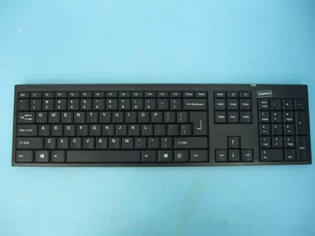
OO9GK381
Jun 17, 20152.4GHz Wirteless Keyboard
Equipment Class
DXX - Part 15 Low Power Communication Device Transmitter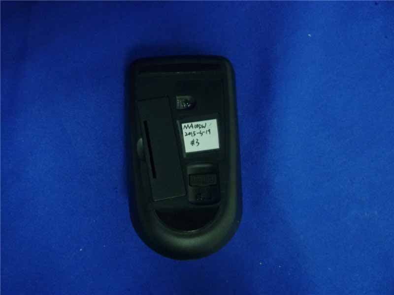
OO9MA105W
May 06, 20152.4GHz Wireless Mouse
Equipment Class
DXX - Part 15 Low Power Communication Device Transmitter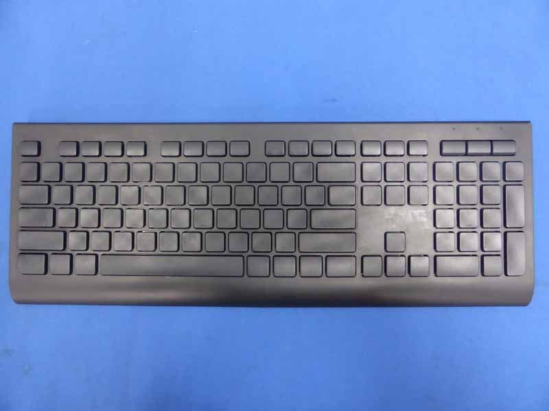
OO9KB313W
May 06, 20152.4GHz Wireless Keyboard
Equipment Class
DXX - Part 15 Low Power Communication Device Transmitter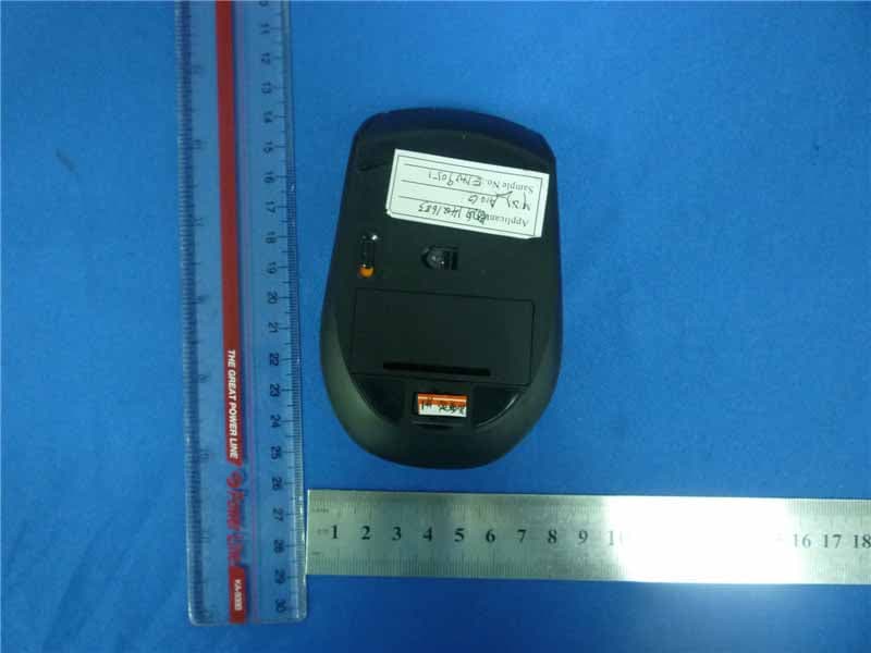
OO9A10G
Oct 16, 20142.4GHz Wireless Mouse
Equipment Class
DXX - Part 15 Low Power Communication Device Transmitter