OPA-FT-512FT-512 Trailblazer Multifunctional Digital Radio
Carlson Wireless Technologies Inc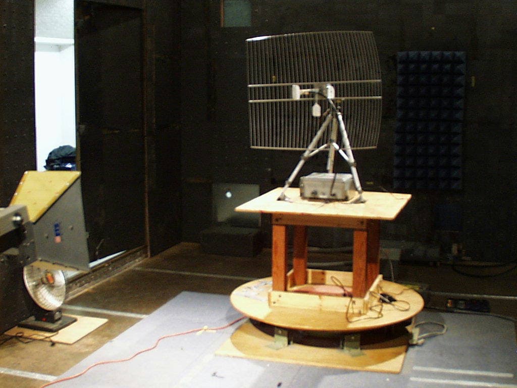
Click to zoom
Application Details
- Equipment Class
- DTS - Digital Transmission System
- Date of Grant
- Dec 19, 2002
- Application Purpose
- Original Equipment
- Date of Application
- Dec 19, 2002
- Equipment Note
- FT-512 Trailblazer Multifunctional Digital Radio
- Frequency Range
- 2412.00000000 - 2460.00000000
- Country
- United States
Documents & Files
Document Text
Text extracted from the exhibit documents filed with the FCC. Open a document above to read the original.
Users Manual
Installation & User’s Manual FT-512 Trailblazer Multifunctional Digital Radio Optional ADD-ONS Include: 4, POTS lines voice plug-in card 8, POTS lines voice plug-in card 1, Ethernet on-board port activation 3 Additional V.35 port plug-in card Part Number 490-1600 Rev 1.09 Oct 2002 FT-512 Trailblazer Installation and User Manual version 1.09 ii Trademark Information i-WLL, the i-WLL logo , Trailblazer, the Trailblazer logo, are registered trademarks of Carlson Wireless Technologies Inc. Windows is a registered trademark of Microsoft Corporation, US Headquarters: 1180-B Evergreen Road Redway, CA 95560 USA Presales Inquires and Applications Support Please contact your local distributor or the Carlson Wireless sales department Tel: +1 707 923 3000 Fax: +1 707 923 1913 Email: [email protected] URL: http://www.carlsonwireless.com Customer Service, Product Support Information, and Training Technical support is available Monday - Friday, 9:00 am to 4:30 pm, PDT. Tel: +1 707 923 4736 Email: [email protected] URL: http://www.carlsonwireless.com/support.html Repair and Return Carlson Wireless will replace or repair this product within two years from the date of shipment if it does not meet its published specification, or if it fails while in service. A return material authorization (RMA) is required prior to returning equipment to Carlson Wireless. Training The Trailblazer support department offers training classes including overviews on: applications engineering, in house testing, configuration, field testing and maintenance. Please contact our customer support department for more specific details. The information contained in this publication is the latest available, however, Carlson Wireless reserves the right to change specifications of hardware and software without prior notice. Purchasers of Carlson products should make their own evaluation to determine the suitability of each such product for their specific application. Carlson Wireless’s obligations regarding the use or application of its products shall be limited to those commitments to the purchaser set forth in its Standard Terms and Conditions of Sale for a delivered product. Use of this manual is also limited to the terms and conditions stated in the contract between Carlson Wireless Inc. and the purchaser. Copyright © 2002 Carlson Wireless, Inc. All Rights Reserved. FT-512 Trailblazer Installation and User Manual version 1.09 iii SAFETY WARNINGS Potentially hazardous voltages exist on TELCO lines and associated equipment. Always observe standard safety precautions during installation, operation, and maintenance of these products. To avoid the possibility of electric shock, be sure to disconnect the power from the remote power source before you perform any line connections or repairs. Always disconnect all the cables connected to the system before disconnecting the grounding connection. After disconnecting the power allow a few seconds for the internal capacitances to discharge before accessing the boards. QUALIFIED PERSONNEL WARNING The installation procedures described in this manual must be performed by qualified personnel aware of the hazards involved. The personnel involved in equipment installation must be trained in the installation of telephone equipment and associated power systems; these personnel must strictly observe all the safety precautions related to the installation of communication equipment. Never install, remove, or adjust equipment and associated cables. Do not work on roofs, masts, or towers during a lightning storm. ATTENTION! STATIC SENSITIVE DEVICES PROPER HANDLING AND GROUNDING PRECAUTIONS REQUIRED. Components within the Trailblazer system are sensitive to electrostatic discharge (ESD). To avoid and prevent ESD damage and device failure maintain proper grounding during configuration, repair or maintenance. This is achieved through the use of an antistatic wrist strap securely connected to chassis ground. Do not use conductive tools for adjusting channel select switch. FCC, RF SAFETY HAZARD WARNING Due to the energy radiated from the antenna, this product must never be mounted such that the cabinet containing the antenna can be closer than 2 Meters ( 6.7 Feet ) to any person. UL INSTALLATION SAFETY INSTRUCTIONS Never install telephone wiring during a lightning storm. Never install telephone jacks in a wet location unless the jack is specifically designed for wet locations. Never touch telephone wires or terminals unless the telephone line has been disconnected at the network interface. Use caution when installing or modifying telephone lines. ! ! FT-512 Trailblazer Installation and User Manual version 1.09 iv Connection to the Telephone Network The equipment complies with Part 68 of the FCC rules. You will find the label located on the device. This label contains the FCC Registration Number and the Ringer Equivalence Number ((REN) for this equipment. You must, upon request, provide this information to your telephone company. The REN is useful to determine the quantity of devices that may be connected to the telephone line and still have all of those devices ring with an incoming call signal. In most areas the sum of the REN’s of all devices connected to one line should not exceed five (5.0). Confirm the number of devices possible on the telephone line (in REN) by contacting the local telephone company who provides the service. Incidence of Harm If your telephone equipment causes harm to the telephone network, the telephone company may disconnect your service temporarily. If possible, they will notify you in advance. But if advance notice is not practical, you will be notified as soon as possible. You will be informed of your right to file a compliant with the FCC. Rights of the Telephone Company Your telephone company may make change in its facilities, equipment, operations or procedures that could affect the proper functioning of your equipment. If they do, you will be notified in advance to …
Text truncated - open the document above for the full version.
Cover Letter(s)
Carlson Wireless Technologies, Inc. • 1180-B Evergreen Rd. • Redway, CA 95560 USA +1-707-923-3000 • fax +1-707-923-1913 • www.carlsonwireless.com • sales@ carlsonwireless.com Requ est f or Co nfidentiality 10 October, 2002 Compliance Certification Services 561F Monterey Road Morgan Hill, CA 95037 Attention: Tom Cokenias Tel 408 463 8704 ext 0 RE: Certification Application FC C ID:OPA- FT- 512 Pl ease be advi sed that the followi ng infor mation is to be held confidential and behalf of Carlson Wireless Technologies Inc.: • Schematics • Bl ock D iagram The appli cation contai ns technical informati on which Carlson Wireless Technologies Inc deems to be trade secr ets and pr opr ietar y. If made publi c, the i nform ation m ight be used to the disadvantage of the appli cant in the mar ket place. Thank you for your attention to this matter. Si gnatory James R. Carlson
Cover Letter(s)
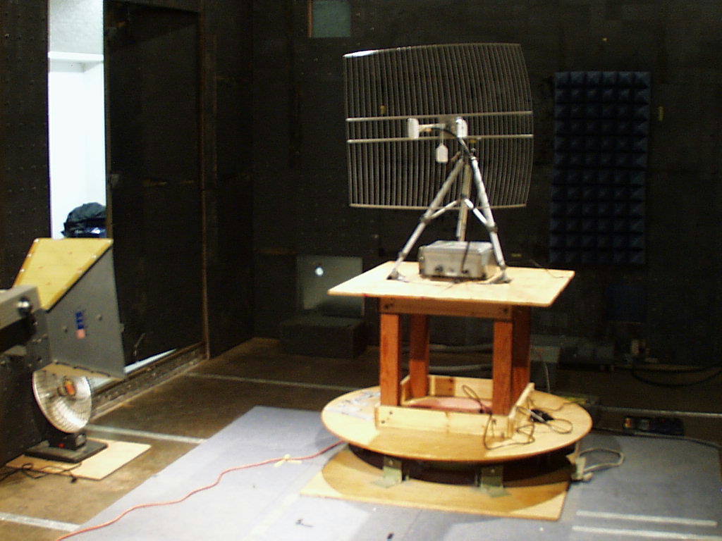
From: Tom Cokenias [[email protected]] Sent: Friday, December 06, 2002 8:44 PM To: Mike Kuo Subject: Re: FW: Carlson Wireless Technologies Inc., FCC ID:OPA-FT-512, AN02T2 419 Hi Mike, Answers follow questions. Hopefully you have all you need to issue certification for this application. If not, please let me know and i will see to it that you get the informatio you need. best rgards Tom >-----Original Message----- >From: CERTADM >Sent: Thursday, December 05, 2002 11:42 AM >To: '[email protected]' >Subject: Carlson Wireless Technologies Inc., FCC ID:OPA-FT-512, >AN02T2419 > > >Notice_content > ------------- Question #1: Please provide external 24dBi antenna photo. ANS 1 Photo attached > >Question #2: Please provide Radiated spurious emission test setup photos to >show the conditions for integral antenna and external antenna. ANS 2 Photos attached > >Question #3: Only channel 1 and Channel 4 radiated spurious emission data >were provided for external antenna. Please provide radiated data for >Channel 5. ANS 3 With the external antenna we could not use Ch 5 because of bandedge emissions in restricted band. Ch 1 and Ch4 are the highest and lowest frequencies that can be used with the external antenna. I have added a note to this effect on page 35 of the user manual, red font for your convenience. > >Question #4: Which antenna portion was measured for RF conducted output >power? Internal antenna connector or external antenna connector. ANS 4 The conducted output measurements were done at the N connector. Please refer to attached photos for details. The internal antenna is mounted in the case and has a cable that permanently attached at the antenna, and has a reverse SMA connector at the other end. The reverse SMA goes to a mating connection at the radio circuit can. When using the external antenna, the internal antenna cable is disconnected, and the coax cable attached to the N connector was attached to the radio. Since both coax cables are the same length, the cable loss is the same, so the same power would be delivered to the N connector or to the internal antenna > >Question #5: Please include these wordings in the RF warning statement in >the user manual " Must not be co-located or operating in conjunction with >any other antenna or transmitter ". ANS 5 I have updated page 42 of the manual to include this wording. The wording I added is in red type for your convenience. > >Best Regards > >Mike Kuo >The items indicated above must be submitted before processing can continue >on the above referenced application. Failure to provide the requested >information within 60 days of the original e-mail date may result in >application dismissal and forfeiture of the filing fee. Also, please note >that partial responses increase processing time and should not be submitted. >Any questions about the content of this correspondence should be directed to >the e-mail address listed below the name of the sender.
Cover Letter(s)
Antenna Connector information for Carlson Wireless FT-512 FCC ID: OPA-FT-512 Rule part: 15.203, 15.204 The internal antenna connects to the radio antenna port via reverse SMA. When using an external antenna, the internal antenna cable is disconnected. The N connector mounted on the side of the EUT housing has a short cable with a reverse SMA connector. This cable is connected to the radio antenna port, and a 24 dBi parabolic reflector antenna is connected to the N-connector. The FT512 is not sold to the general public, and the use of an external antenna with Model FT-512 Trailblazer Pro system mandates professionally trained personnel to ensure compliance with FCC rules and regulations.
External Photos
Carlson Wireless FT512 Product PicturesFCC ID: OP A- FT- 512 Top view Carlson Wireless FT512 Product PicturesFCC ID: OP A- FT- 512 Side View Carlson Wireless FT512 Product PicturesFCC ID: OP A- FT- 512 Bottom View
Internal Photos
Carlson Wireless FT512 Product PicturesFCC ID: OP A- FT- 512 Top view, lid open, showing built-in antenna Carlson Wireless FT512 Product PicturesFCC ID: OP A- FT- 512 EUT pcb board, mounted underneath built-in antenna Carlson Wireless FT512 Product PicturesFCC ID: OP A- FT- 512 EUT pcb board, top view Carlson Wireless FT512 Product PicturesFCC ID: OP A- FT- 512 EUT pcb board, bottom Carlson Wireless FT512 Product PicturesFCC ID: OP A- FT- 512 Built-in antenna, detail, showing coax connection Carlson Wireless FT512 Product PicturesFCC ID: OP A- FT- 512 AC/DC converter used with EUT
Operational Description
FT-512 Trailblazer Installation and User Manual version 1.09 1 1 Introduction 1.1 Scope of Manual The purpose of this manual is to provide planning and installation personnel with the appropriate procedures to plan and install the FT-512 Trailblazer Digital Microwave Radio. To avoid harm to persons or damage to the product please ensure that you have read through the safety, unpacking and installation sections before proceeding. 1.2 Functional Overview The FT-512 provides a reliable, wireless voice and high-speed data connection up to a distance of 50 km. This radio is specifically designed for easy integration with our voice and data multiplexer cards, or any standard V.35 serial device. In addition, Carlson Wireless Technologies Inc. (CWT) also offers a multipoint card cage that will link together the serial data through our network interface card allowing up to 4 E1’s/T1’s connection into the public switched telephone network. CWT can provide excellent price/performance solutions for many of the worlds telecommunication needs both in a point to point or point to multipoint topologies. The initial release is using a 2.4 GHz radio frequency band, however others are scheduled to follow in the 3.5 and 5.7 GHz radio bands in 1Q2003. FT-512 Trailblazer Installation and User Manual version 1.09 2 1.2.1 Main Features 512 or 256 kb/s Synchronous Data Stream with Frame Sync – Structured for high quality PCM voice use, V.35 serial data peripherals, or optionally an 10 MB/s Ethernet network port. Full configurable through a PC – Simplify the setup using our Graphics User Interface application – Data speed, CDMA code, Clocking, Master/Slave and selection of the user frequency pool are configurable in minutes with a serial Com port. Repeater – This product can act as a repeater by just connecting the serial data port back to back with another unit and setting the external clock to yes on the master side. Standard ISO 2593 V.35 DTE port – plugs right in to most V.35 devices Low Power Draw – The FT-512 uses between _ to 2 watts of power and accepts any voltage between 12 and 48 VDC. Very Expandable- You can start out with only one link and, utilizing a card cage, continue to add cards linking together the data and thus gain the features of a point to multipoint topology. Thus you can continue expanding without loosing any of your original investment. Private and Secure – Encrypted CDMA spread spectrum modulation, proprietary framing, structure and packet size assures complete privacy. Wire-line Quality Voice and Data – Data speeds are selectable up to 512 kb/s. Designed to integrate seamlessly with our full bandwidth 64kb PCM POTS cards for high quality voice line/trunks. Optional 10 MB/s Ethernet port on-board - For simultaneous LAN / IP data and PCM voice needs Affordable – The “per pair” pricing of the FT-512 is comparable to the “single unit” of other data radios not designed for voice and PSTN integration. FT-512 Trailblazer Installation and User Manual version 1.09 3 1.3 Optional Add-on Boards 1.3.1 Point to point The FT-512 is a powerful voice and/or data machine that can operate as a stand alone point to point microwave link. Optional voice and data plug-in cards are also available for your current and future growing needs: 4, POTS lines voice plug-in card Four, full bandwidth 64kb PCM, POTS lines can be extended to one location, eliminating the need for external multiplexers. 8, POTS lines voice plug-in card Eight, POTS lines can be extended to one location, eliminating the need for external multiplexers and can be configured as full bandwidth 64kb PCM or 32kb ADPCM to accommodate your data needs as well! 1, 10BaseT, Ethernet bridge port With this unique option, line quality circuit switched voice can be used along with high-speed LAN data traffic, possibly eliminating the need of a router! 4, port, shared V.35 data plug-in card Why set-up several individual data links when you can extend four data ports to one location and share the cost between customers? 1.3.2 Multipoint 18 Slot Card Cage with 100 watt power supply You can have up to 15 villages, each served with up to 8, 64 kb PCM non blocking telephone lines/trunks integrated into one card cage along with an E1 or T1 direct digital connection. 1 or 2 time slots can be used for providing Internet. 4 E1, V52, Network Interface Card With this optional Card Cage and 4 E1, Network Interface Card, you can provide up to 120 users with high quality voice and high speed Internet connectivity along with remote monitoring and diagnostics. 4 T1, GR303, Network Interface Card With this optional Card Cage and 4 T1, Network Interface Card, you can provide up to 96 users with high quality voice and high speed Internet connectivity along with remote monitoring and diagnostics. FT-512 Trailblazer Installation and User Manual version 1.09 4 1.4 Application and System Design Considerations 1.4.1 Point to Point Microwave Link Security Monitoring Cameras Public Safety Data Links Point to Point Commercial Data Links Cellular Backhaul Data Needs Permanent or Temporary Telephone Service Emergency and Disaster Relief Public Calling Phones Leased Line Emulation Islands and other Isolated Areas 1.4.2 Multipoint Microwave Link Internet Café and Telephone Calling Centers Wireless Digital Local Loop (Rural Telephone) FT-512 Trailblazer Installation and User Manual version 1.09 5 1.5 General Specifications Note: More technical details are found in the Appendix of this manual Data Interfaces Primary Serial Data PortV.35 using a DB 25 Connector (RS-422/RS- 232) Data Rate and Type 256/512 kbps, Synchronous Command PortRS-232, 9600 bps, N,8,1 Latencyless than 5 ms. Power Requirements Input Voltage12 to 48 Vdc Power Consumption2 Watts in full operation (does not include add- on cards) RF Specifications RF Frequency Band2.400 to 2.4835 GHz 2.350 to 2.500 Optional for export only! RF Channels Programmable in 1 MHz steps RF Signal Bandwidth12 MHz (7 non overlapping channels) …
Text truncated - open the document above for the full version.
RF Exposure Info
Sheet1 Carlson Wireless FCC ID: OPA-FT-512 RF Hazard Distance Calculation mW/cm2 from Table1:1.00 Max RF Power TX AntennaMPE P, dBmG, dBiSafe Distance, cm 17.613.810.5 17.624.033.9 Basis of Calculations: E^2/3770 = S, mW/cm2 E, V/m = (Pwatts*Ggain*30)^.5/d, meters d = ((Pwatts*G*30)/3770*S))^0.5Pwatts*Ggain = 10^(PdBm-30+GdBi)/10) NOTE: For fixed location transmitters, minimum separation distance is 2 meter, even if calculations indicate MPE distance is less Page 1
Test Report
1 EMISSIONS TEST REPORT FOR A LOW POWER TRANSMITTER I. GENERAL INFORMATION Requirement:Federal Communications Commissions Test Requirements: 15.205, 15.207, 15.209, 15.247 Applicant: Carlson Wireless Inc. 1180-B Evergreen Rd Redway, CA 95560 USA Product ID: FCC ID: OPA-FT-512 This product is not sold directly to end users. Systems will be sold only to CWT's Authorized Resellers. Those authorized resellers are technically trained by CWT's Engineers periodically and must follow the rules set by CWT. II. DESCRIPTION OF EQUIPMENT UNDER TEST (EUT) RF Specifications RF Frequency Band2.400 to 2.4835 GHz RF Channels Programmable in 1 MHz steps RF Signal Bandwidth12 MHz (6 non overlapping channels) PN Code Rate11 M chip/sec PN Code Length16 Spreading codes4 programmable non orthogonal codes Modulation TypeBPSK (256) or QPSK (512kbs) DSSS Transmitter Output Power+17dBm, set to allow CDMA operation Antennas Built-in (13.8 dBi gain) or External parabolic (24 dBi) III. TEST LOCATION All emissions tests were performed at: Compliance Certification Services 571F Monterey Road Morgan Hill, CA 95037 T.N. Cokenias20 November 2002 EMC Consultant/Agent for Carlson Wireless 2 TEST PROCEDURES Measurement Equipment Used: TEST EQUIPMENTS LIST Name of EquipmentManufacturerModel No.Serial No. Line FilterLindgren 10k - 10GHzLMF-3489497 LISNFischer 9k - 100MHzFCC-LISN-50/250-25-2114 EMI Test ReceiverRohde & SchwarzESHS 20827129/006 Quasi Peak AdapterHP9K - 1GHz85650A2811A01155 Spectrum DisplayHP85662A2816A16696 Spectrum AnalyzerHP 0.1K - 1.5GHz8568B2732A03661 RF PreselectorHP20Hz-2GHz85685A2817A00756 Pre-Amplifier,25 dBHP0.1 - 1300MHz8447D (P8)2944A06589 Antenna, BilogSchaffner-Chase30M-2GHzCBL6112B2586 Pre-AmplifierMITEQ1-26GHzNSP2600-44646456 Horn Antenna(1 - 18GHz)EMCO31156717 Spectrum AnalyzerHP8593EM3710A00205 Filter 4.5GHzFSY MicrowaveFM-4570-9SS3 Power MeterAgliente441gb41291160 Radiated Emissions Test Requirement: 15.109, 15.205, 15.209, 15.247 Test Procedures, 1- 26 GHz: 1. The EUT was placed on a wooden table resting on a turntable on the open air test site. The search antenna was placed 3m from the EUT. The EUT antenna was mounted vertically as per normal installation. 2. The turntable was slowly rotated to locate the direction of maximum emission at each emission falling in the restricted bands of 15.205. 3. Radiated emissions were investigated for a LOW channel, a MID channel, and HIGH channel. Emissions were investigated to the 10 th harmonic. 4. Once maximum direction was determined, the search antenna was raised and lowered in both vertical and horizontal polarizations. The maximum readings so obtained are recorded in the data listed below. 3 Radiated Test Set-up, 1-40 GHz d: 1-3m 1-2m d -or- preamplifier Fig. 1 Testing was performed at 3 different frequencies ChannelFrequency, MHz Low2412 Mid2448 High2460 Radiated emissions were performed at each frequency for 2 different transmitter antennas. Antennas tested: Antenna TypeGainAntenna Manufacturer Model Number Integral13.8 dBiCarlton Wirelessn/a external w/reflector24 dBivarious n/a Test Results: Worst case results are presented. Refer to separate Excel spread sheet files. NOTE: For radiated emissions that fall on restricted bands per 15.205, emissions limit is 54 dBuV/m at 3 m for emissions above 960 MHz. Data plots presented for internal antenna show corrected field strengths at band edges (REF OFFSET values are correction factors). The band edge field strengths for the external antenna were obtained with Marker Delta method. Per 15.247(c) all other undesired emissions must be 20 dB below the highest in-band emission when measured in a 100 kHz bandwidth. Conducted measurements are presented for emissions up to 26.5 GHz. Low Channel 11/07/02 FCC Measurement Compliance Certification Services, Morgan Hill Open Field Site Test Engr:NEELESH RAJ Project #:02U1641 Company:CARLSON WIRELESS EUT Descrip.:2.4GHZ SPREAD SPECTRUM W/LAN EUT M/N:FT512 Test Target:FCC Equipment for 1-22 GHz:Equipment for 22 - 58 GHz: HP8593EM AnalyzerHP8566B Analyzer Miteq NSP2600-44 PreampHP 11975A Amplifier (LO) EMCO 3115 AntennaHP 11970K External mixer/antenna Cable:15.0feetCable: IF Only (321 MHz) Peak Measurements:Average Measurements: 1 MHz Resolution Bandwidth1MHz Resolution Bandwidth 1MHz Video Bandwidth10Hz Video Bandwidth fDistRead PkRead Avg.AFCLAmpD CorrHPFPeakAvgPk LimAvg LimPk MarAvg MarNotes GHzfeetdBuVdBuVdB/mdBdBdB dBuV/mdBuV/mdBuV/mdBuV/mdBdB HARMONICS 4.8243.359.845.533.95.7-36.1-9.51.054.940.574.054.0-19.1-13.5V 7.2363.369.546.337.07.2-36.3-9.51.068.945.774.054.0-5.1-8.3V 9.6473.355.242.038.58.5-35.4-9.51.058.345.174.054.0-15.7-8.9V 12.0503.353.143.439.39.5-36.3-9.51.057.147.474.054.0-16.9-6.6V 4.8243.363.541.733.95.7-36.1-9.51.058.536.774.054.0-15.5-17.3H 7.2363.361.945.137.07.2-36.3-9.51.061.344.674.054.0-12.7-9.4H 9.6473.354.741.238.58.5-35.4-9.51.057.844.374.054.0-16.2-9.7H 12.0503.352.442.339.39.5-36.3-9.51.056.446.374.054.0-17.6-7.7H SPURIOUS 4.2603.364.252.333.15.3-36.1-9.51.058.046.074.054.0-16.0-8.0V 6.3903.349.941.335.56.8-36.3-9.51.047.438.774.054.0-26.6-15.3V 4.2603.363.252.533.15.3-36.1-9.51.057.046.374.054.0-17.0-7.7H 6.3903.352.141.535.56.8-36.3-9.51.049.639.074.054.0-24.4-15.0H fMeasurement FrequencyAmpPreamp GainAvg LimAverage Field Strength Limit DistDistance to AntennaD CorrDistance Correct to 3 metersPk LimPeak Field Strength Limit ReadAnalyzer ReadingAvgAverage Field Strength @ 3 mAvg MarMargin vs. Average Limit AFAntenna FactorPeakCalculated Peak Field StrengthPk MarMargin vs. Peak Limit CLCable LossHPFHigh Pass Filter IntAntRAD.xls Mid Channel(4) 11/07/02 FCC Measurement Compliance Certification Services, Morgan Hill Open Field Site Test Engr:NEELESH RAJ Project #:02U1641 Company:CARLSON WIRELESS EUT Descrip.:2.4GHZ SPREAD SPECTRUM W/LAN EUT M/N:FT512 Test Target:FCC Equipment for 1-22 GHz:Equipment for 22 - 58 GHz: HP8593EM AnalyzerHP8566B Analyzer Miteq NSP2600-44 PreampHP 11975A Amplifier (LO) EMCO 3115 AntennaHP 11970K External mixer/…
Text truncated - open the document above for the full version.
Test Report
561F Monterey Road, San Jose, CA 95037 USA Tel: (408) 463-0885 Fax: (408) 463-0888 Data#: 7File#: 02U1641D.EMIDate: 11-08-2002 Time: 16:24:03 Level (dBuV)Compliance Certification Service 80 35 -10 0.4530 Frequency (MHz) 1.2.5.1020 FCC CLASS-B Trace: 5 Ref Trace: Project # : 02u1641 Test Engineer : NEELESH RAJ Company : CARLSON WIRELESS EUT : 2.4GHz SPREAD SPECTRUM W/LAN Model Name : FT512 Test Config. : EUT/AC ADAPTER Test of Target: EN55022 Class B Mode of Op. : TRANSMITTING : 115VAC@60Hz : L1 (peak; black quasipeak; green) 561F Monterey Road, San Jose, CA 95037 USA Tel: (408) 463-0885 Fax: (408) 463-0888 Data#: 7File#: 02U1641C.EMIDate: 11-08-2002 Time: 15:59:20 Level (dBuV)Compliance Certification Service 80 35 -10 0.4530 Frequency (MHz) 1.2.5.1020 FCC CLASS-B Trace: 5 Ref Trace: Project # : 02u1641 Test Engineer : NEELESH RAJ Company : CARLSON WIRELESS EUT : 2.4GHz SPREAD SPECTRUM W/LAN Model Name : FT512 Test Config. : EUT/AC ADAPTER Test of Target: EN55022 Class B Mode of Op. : TRANSMITTING : 115VAC@60Hz : L2 (peak; black quasipeak; green) 561F Monterey Road, San Jose, CA 95037 USA Tel: (408) 463-0885 Fax: (408) 463-0888 Data#: 7File#: 02U1641A.EMIDate: 11-08-2002 Time: 15:31:40 Level (dBuV)Compliance Certification Service 80 35 -10 0.1530 Frequency (MHz) 0.51.2.5.1020 AVERAGE CISPR CLASS-B Trace: 5 Ref Trace: Project # : 02u1641 Test Engineer : NEELESH RAJ Company : CARLSON WIRELESS EUT : 2.4GHz SPREAD SPECTRUM W/LAN Model Name : FT512 Test Config. : EUT/AC ADAPTER Test of Target: EN55022 Class B Mode of Op. : TRANSMITTING : 115VAC@60Hz : L1 (peak; black avg; green) 561F Monterey Road, San Jose, CA 95037 USA Tel: (408) 463-0885 Fax: (408) 463-0888 Data#: 7File#: 02U1641B.EMIDate: 11-08-2002 Time: 15:48:50 Level (dBuV)Compliance Certification Service 80 35 -10 0.1530 Frequency (MHz) 0.51.2.5.1020 AVERAGE CISPR CLASS-B Trace: 5 Ref Trace: Project # : 02u1641 Test Engineer : NEELESH RAJ Company : CARLSON WIRELESS EUT : 2.4GHz SPREAD SPECTRUM W/LAN Model Name : FT512 Test Config. : EUT/AC ADAPTER Test of Target: EN55022 Class B Mode of Op. : TRANSMITTING : 115VAC@60Hz : L2 (peak; black avg; green) *CISPR DATA CONDUCTED EMISSIONS DATA (115VAC 60Hz) Freq.ReadingClossLimitEN_B Margin (MHz)PK (dBuV)QP (dBuV)AV (dBuV)(dB)QPAVQP (dB)AV (dB) 0.1653.30--45.020.0065.7455.74-12.44-10.72 2.9842.12--26.790.0056.0046.00-13.88-19.21 0.3241.93--29.020.0061.2951.29-19.36-22.27 0.1556.64--43.450.0066.0056.00-9.36-12.55 3.0437.94--17.130.0056.0046.00-18.06-28.87 1.7837.16--12.500.0056.0046.00-18.84-33.50 6 Worst Data *FCC DATA CONDUCTED EMISSIONS DATA (115VAC 60Hz) Freq.ReadingClossLimitFCC_B Margin (MHz)PK (dBuV)QP (dBuV)AV (dBuV)(dB)QPAVQP (dB)AV (dB) 16.0545.4244.56--0.0048.00---3.44-- 3.0242.3239.64--0.0048.00---8.36-- 3.1340.8234.10--0.0048.00---13.90-- 16.0544.6643.92--0.0048.00---4.08-- 3.0342.8739.16--0.0048.00---8.84-- 3.1640.8035.10--0.0048.00---12.90-- 6 Worst Data Remark L1 / L2 L1 L1 L1 L2 L2 L2 Remark L1 / L2 L1 L1 L1 L2 L2 L2
Contact Information
Applicant
James R. Carlson(CEO)
Test Firm
Compliance Certification Services IncSteve Cheng
Technical Specifications
| # | Rule Parts | Frequency Range | Power Output |
|---|---|---|---|
| 1 | 15C | 2.41 GHz - 2.46 GHz | 56.00 mW |
Other Applications from Carlson Wireless Technologies Inc

OPA-RC2-CPE
Jan 07, 2014White Space Broadband Radio
Equipment Class
WGF - White Space Device with Geo-location- Fixed
OPA-RC2-BS
Dec 12, 2013White Space Broadband Radio
Equipment Class
WGF - White Space Device with Geo-location- Fixed
OPA-TB59
Jul 26, 2011Network Transmission Equipment
Equipment Class
TNB - Licensed Non-Broadcast Station Transmitter
OPA-TB24-58
Jan 16, 2006Trailblazer 2.4 � 5.8
Equipment Class
DTS - Digital Transmission System
OPA-TB49
Jan 13, 2006Trailblazer TB 4.9
Equipment Class
TNB - Licensed Non-Broadcast Station Transmitter