OPA-RC2-CPEWhite Space Broadband Radio
Carlson Wireless Technologies Inc
Click to zoom
Application Details
- Equipment Class
- WGF - White Space Device with Geo-location- Fixed
- Date of Grant
- Jan 07, 2014
- Application Purpose
- Original Equipment
- Date of Application
- Aug 01, 2013
- Equipment Note
- White Space Broadband Radio
- Frequency Range
- 623.00000000 - 695.00000000
- Country
- United States
Documents & Files
Document Text
Text extracted from the exhibit documents filed with the FCC. Open a document above to read the original.
Users Manual
PRELIMINARY RELEASE *** This is a confidential document. Do not distribute. *** Revised December 2, 2013 RuralConnect ® TV White Space Radio Installation & User Guide Carlson Wireless Technologies, Inc. 2700 Foster Avenue, Arcata, CA 95521 Tel: (707) 822-7000 Fax: (707) 822-7010 www.CarlsonWireless.com PRELIMINARY RELEASE *** This is a confidential document. Do not distribute. *** Trademarks RuralConnect® and the RuralConnect® logo are registered trademarks of Carlson Wireless Technologies, Inc. Windows® is a registered trademark of the Microsoft Corporation in the United States and other countries. Copyright Copyright© 2013 Carlson Wireless Technologies, Inc. All Rights Reserved. No person may reproduce this manual without explicit permission from Carlson. The information contained in this publication is the latest available, as of the date printed on each page. Carlson reserves the right to make changes without notice. Current revisions are available upon request. Carlson Headquarters: 2700 Foster Avenue, Arcata, CA 95521 USA Sales Inquiries and Application Support Please contact the Carlson Sales Department for sales and/or application inquiries. Purchasers of Carlson products are required to make their own evaluations of product suitability for their specific application(s). Carlson’s obligations regarding the use and/or application of our products and/or the use of this manual are limited to the terms set forth in the Standard Terms and Conditions of Sale for a delivered product. Technical Support Training and support are only available for products purchased directly from Carlson; the purchaser is responsible for technical assistance for all other system components. Carlson Support is available from 7:30 AM to 4:30 PM Pacific Standard Time, excluding weekends and holidays. Tel: +1 (707) 822-7000 Email: [email protected] Repair and Return Carlson will replace or repair this product within one year from the date of shipment if it does not meet published specifications, or if it fails while in service due to a manufacturer’s defect. You must obtain a return merchandise authorization (RMA) prior to returning equipment to Carlson. You can request an RMA on our web site at http://www.carlsonwireless.com/support/rma- request.html. Safety Warnings In order to prevent personal injury, property damage, and/or equipment failure, it is essential that the installer employ appropriate safety measures when testing, installing, or maintaining RuralConnect® equipment. You are required to review all safety warnings in this manual prior to testing, installing, and/or maintaining the system. Qualified Personnel Professionally trained service technicians are the only personnel qualified to perform the testing and/or configuration steps outlined in this manual. Technicians are responsible for adhering to all applicable safety regulations and industry-standard best practices. Carlson does not Page | 2 PRELIMINARY RELEASE *** This is a confidential document. Do not distribute. *** authorize non-qualified personnel to work on equipment without the direct supervision of a professionally trained service technician. Proper Handling and Grounding The electronic components of the RuralConnect® equipment are sensitive to electrostatic discharge (ESD). In order to prevent potential warranty voiding damage, you must use an adequately grounded anti-static wrist strap when handling the equipment. It is also important to avoid the use of conductive tools. In order to prevent electric shock, always disconnect the remote power source and all cables from the system prior to disconnecting the grounding connection. Installation You must never perform any installation work on a tower, mast, or rooftop during lightning storms or other inclement weather. Dangerous work of this nature could result in serious injury and/or death. It is important to adhere to all of the applicable local, state, and federal regulations pertaining to safety equipment and tower climbing practices. RF Hazards Per FCC regulations, RuralConnect® systems must be installed in a manner that ensures a minimum of 40 centimeters (15.7 inches) separation between the antenna and any person. Failure to do so could result in a fine and/or personal injury. RF Exposure The radio described in this manual transmits RF energy. The concentrated energy from the antenna may pose a health hazard. All antennas used with this radio must be installed to provide a minimum separation from all persons of 40 cm (15.7 inches). The above separation distance must be maintained at all times. More information can be obtained from the FCC at the following website: http://www.fcc.gov/Bureaus/Engineering_Technology/Documents/bullet ins/oet65/oet65.pdf Regulatory Compliance Information Per Part 15 of the FCC regulations, the RuralConnect® operates within the specified limits of a Class A digital device. Those limits ensure reasonable protection from harmful interference when operating the equipment in a commercial setting. This system generates, utilizes, and may radiate radio frequency energy. Incorrect installation and/or equipment use inconsistent with the instructions in the manual may result in harmful interference to radio communications. Operation of this equipment in a residential area may cause harmful interference in which case the user will be required to correct the interference at his or her expense. RuralConnect® operation is subject to the following two conditions: 1. This device may not cause harmful interference. 2. This device must accept any interference received, including interference that may cause undesired operation. Page | 3 PRELIMINARY RELEASE *** This is a confidential document. Do not distribute. *** Additional Information on TV Band Interference Protection This equipment has been tested and found to comply with the rules for TV band devices, pursuant to Part 15 of the FCC Rules. These rules are designed to provide reasonable protection against ha…
Text truncated - open the document above for the full version.
Users Manual
PRELIMINARY RELEASE *** This is a confidential document. Do not distribute. *** Revised December 12, 2013 RuralConnect ® TV White Space Radio Installation & User Guide Carlson Wireless Technologies, Inc. 2700 Foster Avenue, Arcata, CA 95521 Tel: (707) 822-7000 Fax: (707) 822-7010 www.CarlsonWireless.com PRELIMINARY RELEASE *** This is a confidential document. Do not distribute. *** Trademarks RuralConnect® and the RuralConnect® logo are registered trademarks of Carlson Wireless Technologies, Inc. Windows® is a registered trademark of the Microsoft Corporation in the United States and other countries. Copyright Copyright© 2013 Carlson Wireless Technologies, Inc. All Rights Reserved. No person may reproduce this manual without explicit permission from Carlson. The information contained in this publication is the latest available, as of the date printed on each page. Carlson reserves the right to make changes without notice. Current revisions are available upon request. Carlson Headquarters: 2700 Foster Avenue, Arcata, CA 95521 USA Sales Inquiries and Application Support Please contact the Carlson Sales Department for sales and/or application inquiries. Purchasers of Carlson products are required to make their own evaluations of product suitability for their specific application(s). Carlson’s obligations regarding the use and/or application of our products and/or the use of this manual are limited to the terms set forth in the Standard Terms and Conditions of Sale for a delivered product. Technical Support Training and support are only available for products purchased directly from Carlson; the purchaser is responsible for technical assistance for all other system components. Carlson Support is available from 7:30 AM to 4:30 PM Pacific Standard Time, excluding weekends and holidays. Tel: +1 (707) 822-7000 Email: [email protected] Repair and Return Carlson will replace or repair this product within one year from the date of shipment if it does not meet published specifications, or if it fails while in service due to a manufacturer’s defect. You must obtain a return merchandise authorization (RMA) prior to returning equipment to Carlson. You can request an RMA on our web site at http://www.carlsonwireless.com/support/rma- request.html. Safety Warnings In order to prevent personal injury, property damage, and/or equipment failure, it is essential that the installer employ appropriate safety measures when testing, installing, or maintaining RuralConnect® equipment. You are required to review all safety warnings in this manual prior to testing, installing, and/or maintaining the system. Qualified Personnel Professionally trained service technicians are the only personnel qualified to perform the testing and/or configuration steps outlined in this manual. Technicians are responsible for adhering to all applicable safety regulations and industry-standard best practices. Carlson does not Page | 2 PRELIMINARY RELEASE *** This is a confidential document. Do not distribute. *** authorize non-qualified personnel to work on equipment without the direct supervision of a professionally trained service technician. Proper Handling and Grounding The electronic components of the RuralConnect® equipment are sensitive to electrostatic discharge (ESD). In order to prevent potential warranty voiding damage, you must use an adequately grounded anti-static wrist strap when handling the equipment. It is also important to avoid the use of conductive tools. In order to prevent electric shock, always disconnect the remote power source and all cables from the system prior to disconnecting the grounding connection. Installation You must never perform any installation work on a tower, mast, or rooftop during lightning storms or other inclement weather. Dangerous work of this nature could result in serious injury and/or death. It is important to adhere to all of the applicable local, state, and federal regulations pertaining to safety equipment and tower climbing practices. RF Hazards Per FCC regulations, RuralConnect® systems must be installed in a manner that ensures a minimum of 40 centimeters (15.7 inches) separation between the antenna and any person. Failure to do so could result in a fine and/or personal injury. RF Exposure The radio described in this manual transmits RF energy. The concentrated energy from the antenna may pose a health hazard. All antennas used with this radio must be installed to provide a minimum separation from all persons of 40 cm (15.7 inches). The above separation distance must be maintained at all times. More information can be obtained from the FCC at the following website: http://www.fcc.gov/Bureaus/Engineering_Technology/Documents/bullet ins/oet65/oet65.pdf Regulatory Compliance Information Per Part 15 of the FCC regulations, the RuralConnect® operates within the specified limits of a Class A digital device. Those limits ensure reasonable protection from harmful interference when operating the equipment in a commercial setting. This system generates, utilizes, and may radiate radio frequency energy. Incorrect installation and/or equipment use inconsistent with the instructions in the manual may result in harmful interference to radio communications. Operation of this equipment in a residential area may cause harmful interference in which case the user will be required to correct the interference at his or her expense. RuralConnect® operation is subject to the following two conditions: 1. This device may not cause harmful interference. 2. This device must accept any interference received, including interference that may cause undesired operation. Page | 3 PRELIMINARY RELEASE *** This is a confidential document. Do not distribute. *** Additional Information on TV Band Interference Protection This equipment has been tested and found to comply with the rules for TV band devices, pursuant to Part 15 of the FCC Rules. These rules are designed to provide reasonable protection against h…
Text truncated - open the document above for the full version.
Parts List/Tune Up Info
Log Periodic Directional UHF Antenna for RuralConnect ® CPE Gain 9 dBi VSWR 1.5:1 Active Elements 10 Element Diameter 3/16” Beamwidth 35° vertical, 30° horizontal Maximum Height 14” Maximum Length 15” Polarization Vertical or horizontal Shipping Weight 2 lbs. Connector F-type connector Output Impedance 75 ohm Wind Rating 125 mph Wind Load 8.1 lbs Front to Back Ratio 20 dB Power Rating 150 Watts Material Aluminum and brass booms Carlson Wireless Technologies, Inc. 2700 Foster Avenue Arcata, CA 95521 USA T: +1 707.822.7000 F: +1 707.822.7010 E: [email protected] UPS Shippable! Specs subject to change without notice COMTELCO Technical SpecificationY42400WB ________________________________________________________________ 400MHz-800MHz 7dBd / 9dBi WIDE BAND YAGI ANTENNA High Performance: This 10 element yagi antenna provides 7dBd /9dBi gain with excellent wide band performance. Rugged and weatherproof: Our hybrid radome construction provides excellent weather protection for our driven element. The radome is constructed of UV inhibited ABS. The heavy duty mounting plate is extruded aluminum. Stainless steel V bolts are provided for long term reliability and resistance to corrosion. Lightweight and Durable: This yagi antenna is easily installed by one person, yet is designed to withstand 125 MPH winds. Termination Options: Type A: 12" Teflon pigtail with N connector. ELECTRICAL SPECIFICATIONS GAIN: 7dBd / 9dBi FREQUENCY@ VSWR <1.5:1 400-800MHz <2.2:1400-1000MHz F to B RATIO: 20dB VERT BEAMWIDTH: 35 ° HORIZ BEAMWIDTH: 30 ° POWER RATING: 150 watts IMPEDANCE: 50 ohms MECHANICAL SPECIFICATIONS MATERIAL: Aluminum & Brass booms 3/16" solid elements RADOME: 3" UV inhibited ABS LENGTH: 15" HEIGHT:14” WEIGHT: 2 lb. MOUNTING: 2 1/2" mast maximum FLAT PLATE AREA: .12 ft 2 WIND RATING: 125 MPH WIND LOAD: 8.1 lbs. Horizontal Pattern 0 30 60 90 120 150 180 210 240 270 300 330 -15dB-20dB -10dB-5dB Vertical Pattern 0 30 60 90 120 150 180 210 240 270 300 330 -15dB-20dB -10dB-5dB COMTELCO Technical SpecificationY42400WB ________________________________________________________________ 400MHz-800MHz 7dBd / 9dBi WIDE BAND YAGI ANTENNA High Performance: This 10 element yagi antenna provides 7dBd /9dBi gain with excellent wide band performance. Rugged and weatherproof: Our hybrid radome construction provides excellent weather protection for our driven element. The radome is constructed of UV inhibited ABS. The heavy duty mounting plate is extruded aluminum. Stainless steel V bolts are provided for long term reliability and resistance to corrosion. Lightweight and Durable: This yagi antenna is easily installed by one person, yet is designed to withstand 125 MPH winds. Termination Options: Type A: 12" Teflon pigtail with N connector. ELECTRICAL SPECIFICATIONS GAIN: 7dBd / 9dBi FREQUENCY@ VSWR <1.5:1 400-800MHz <2.2:1400-1000MHz F to B RATIO: 20dB VERT BEAMWIDTH: 35 ° HORIZ BEAMWIDTH: 30 ° POWER RATING: 150 watts IMPEDANCE: 50 ohms MECHANICAL SPECIFICATIONS MATERIAL: Aluminum & Brass booms 3/16" solid elements RADOME: 3" UV inhibited ABS LENGTH: 15" HEIGHT:14” WEIGHT: 2 lb. MOUNTING: 2 1/2" mast maximum FLAT PLATE AREA: .12 ft 2 WIND RATING: 125 MPH WIND LOAD: 8.1 lbs. Horizontal Pattern 0 30 60 90 120 150 180 210 240 270 300 330 -15dB-20dB -10dB-5dB Vertical Pattern 0 30 60 90 120 150 180 210 240 270 300 330 -15dB-20dB -10dB-5dB COMTELCO Technical SpecificationY42400WB ________________________________________________________________ 400MHz-800MHz 7dBd / 9dBi WIDE BAND YAGI ANTENNA High Performance: This 10 element yagi antenna provides 7dBd /9dBi gain with excellent wide band performance. Rugged and weatherproof: Our hybrid radome construction provides excellent weather protection for our driven element. The radome is constructed of UV inhibited ABS. The heavy duty mounting plate is extruded aluminum. Stainless steel V bolts are provided for long term reliability and resistance to corrosion. Lightweight and Durable: This yagi antenna is easily installed by one person, yet is designed to withstand 125 MPH winds. Termination Options: Type A: 12" Teflon pigtail with N connector. ELECTRICAL SPECIFICATIONS GAIN: 7dBd / 9dBi FREQUENCY@ VSWR <1.5:1 400-800MHz <2.2:1400-1000MHz F to B RATIO: 20dB VERT BEAMWIDTH: 35 ° HORIZ BEAMWIDTH: 30 ° POWER RATING: 150 watts IMPEDANCE: 50 ohms MECHANICAL SPECIFICATIONS MATERIAL: Aluminum & Brass booms 3/16" solid elements RADOME: 3" UV inhibited ABS LENGTH: 15" HEIGHT:14” WEIGHT: 2 lb. MOUNTING: 2 1/2" mast maximum FLAT PLATE AREA: .12 ft 2 WIND RATING: 125 MPH WIND LOAD: 8.1 lbs. Horizontal Pattern 0 30 60 90 120 150 180 210 240 270 300 330 -15dB-20dB -10dB-5dB Vertical Pattern 0 30 60 90 120 150 180 210 240 270 300 330 -15dB-20dB -10dB-5dB The “log periodic” directional antenna is known for its consistent wide bandwidth capabilities. This antenna displays a very flat gain across the band in long range testing. Its small size makes for easy and unobtrusive installations. Carlson Part Number: 057-470-786-F
RF Exposure Info
Carlson Wireless Technologies, Inc. 2700 Foster Avenue Arcata, CA 95521 Maximum Permissible Exposure Limits MPE Calculations P Transmit Power (mW): 199.57 G Max Antenna Gain (dB): 9 7.943282 Linear Gain R Distance (cm): 22 8.66 inches S Power Density (mW/cm 2 ): 0.295 Limits for General Public (mW/cm 2 ): 473 MHz 0.3153333 587 MHz 0.3913333 695 MHz 0.4633333 f = 30 - 300 MHz 0.2 f = 300 - 1500 MHz f/1500 Adjust R until S < limits above Based on FCC OET Bulletin 65 James Carlson CEO & President Carlson Wireless Technologies 2700 foster Avenue Arcata, CA 95521
Test Report
FCC PART 15.Subpart H White Spaces System PART 1 TEST REPORT Fixed TVBD Device Part 1 Applicant Carlson Wireless Technologies Inc. Address 2700 Foster Ave. Arcata Ca 95521 USA FCC ID OPA-RC2-CPE Model Number RC2 Product Description White Space Fixed TVBD Date Sample Received 1/25/2013 Date Tested 1/30/2013 Tested By Sushant Kadimdivan/ Mario de Aranzeta Approved By Mario de Aranzeta Report Number C\CARLSON\841AUT13\841AUT13TestReport.doc Test Results PASS FAIL THE ATTACHED REPORT SHALL NOT BE REPRODUCED EXCEPT IN FULL WITHOUT THE WRITTEN APPROVAL OF TIMCO ENGINEERING, INC. 849 NW State Road 45 Newberry, FL 32669 USA Ph: 888.472.2424 or 352.472.5500 Fax: 352.472.2030 Email: [email protected] Website: www.timcoengr.com Testing Certificate # 0955-01 APPLICANT. : Carlson Wireless Technologies Inc. FCC ID: OPA-RC2-CPE REPORT: V:\C\CARLSON\841UT13\841AUT13 PART1 TestReport_Rev1.doc Page 2 of 43 TABLE OF CONTENT GENERAL REMARKS ...................................................................................................................................... 3 GENERAL INFORMATION .............................................................................................................................. 4 EMC EQUIPMENT LIST ................................................................................................................................... 5 TEST PROCEDURES ........................................................................................................................................ 6 §15.207 & §15.709(C)(5) POWER LINE CONDUCTED INTERFERENCE ............................................................. 7 §15.209 RADIATION INTERFERENCE ............................................................................................................ 10 §15.709(A) POWER LIMITS FIXED TVBD ..................................................................................................... 16 §15.709(A)(3)(I) TRANSMITTER POWER CONTROL FIXED TVBD .................................................................. 20 §15.709(C)(1) EMISSION LIMITS AT THE BAND EDGE FOR TVBDS ............................................................... 21 §15.709(C)(4) EMISSION IN THE BAND OF 602-620MHZ LIMITS FOR TVBDS ............................................... 32 PRODUCT PHOTOS ...................................................................................................................................... 42 APPLICANT. : Carlson Wireless Technologies Inc. FCC ID: OPA-RC2-CPE REPORT: V:\C\CARLSON\841UT13\841AUT13 PART1 TestReport_Rev1.doc Page 3 of 43 GENERAL REMARKS The attached report shall not be reproduced except in full without the written permission of Timco Engineering Inc. The test results relate only to the items tested. Summary The device under test does: fulfill the general approval requirements as identified in this test report not fulfill the general approval requirements as identified in this test report Attestations The scope of this document is to report the results of the Fixed TVBD Part 1 Radio Frequency Certification Tests. There are three (3) components of the White Spaces technology; - TV Band devices (Fixed TVBD for Certification). - TV Bands Database - TV Band System, Made up of Fixed TVBD’s database, and layer of interaction between the devices and the databases. To the best of my knowledge and belief, these tests were performed using the measurement procedures described in this report. All instrumentation and accessories used to test products for compliance to the indicated standards are calibrated regularly in accordance with ISO 17025: 2005 requirements. Testing Certificate # 0955-01 I attest that the necessary measurements were made, under my supervision, at: Timco Engineering Inc. 849 NW State Road 45 Newberry, Fl 32669 Authorized Signatory Name: Mario de Aranzeta C.E.T. Compliance Engineer/ Lab. Supervisor Date: July 23, 2013 APPLICANT. : Carlson Wireless Technologies Inc. FCC ID: OPA-RC2-CPE REPORT: V:\C\CARLSON\841UT13\841AUT13 PART1 TestReport_Rev1.doc Page 4 of 43 GENERAL INFORMATION Device Under Test (DUT) Description General: White space transceiver for broadband data transfer. DUT Specification Applicable Standard Part 15 Subpart H TV Band White Space Fixed Device DUT Description Transceiver FCC ID OPA-RC2-CPE Application: Rural Broadband Operating Frequency 473 to 599 and 623 to 695 MHz Number of channels CH14 – 35 and 39 – CH51 Bridged Ethernet Port: RJ45 Transmit Power: 23 dBm DUT Power Source 110–120Vac/50– 60Hz DC Power UE-POE-33 Battery Operated Exclusively Test Item Prototype Pre-Production Production Type of Equipment Fixed - WGF Mobile – WG1 Portable – WG2 Fixed - WSF Mobile – WS1 Portable – WS2 Antenna Connector F Connector Antenna Log Periodic UHF FOR CPE (Carlson Part Number: 057-470-786-F) 9dBi gain Network Port RJ 45 Serial Port - Indicators Power Indicator Alarm Indicator Transmit Indicator Test Facility Timco Engineering Inc. 849 NW State Road 45 Newberry, FL 32669 USA. Test Conditions Temperature: 26ºC Relative humidity: 50% Test Exercise The DUT was placed in a mode allowing channel changes and allowing a continuous transmit mode of operation. Compliance with 15.209 limits requires a Laird 28A2736-0A2 ferrite to be applied to the RJ45 cable directly at the output of the EUT. APPLICANT. : Carlson Wireless Technologies Inc. FCC ID: OPA-RC2-CPE REPORT: V:\C\CARLSON\841UT13\841AUT13 PART1 TestReport_Rev1.doc Page 5 of 43 EMC EQUIPMENT LIST Device Manufacturer Model Serial Number Cal/Char Date Due Date 3-Meter Semi- Anechoic Chamber Panashield N/A N/A 3/24/12 3/24/14 AC Voltmeter HP 400FL 2213A14499 CAL 6/12/11 6/12/13 Frequency Counter HP 5385A 2730A03025 CAL 8/17/11 8/17/13 Hygro- Thermometer Extech 445703 0602 CAL 6/15/11 6/15/13 Modulation Analyzer HP 8901A 3435A06868 CAL 7/18/11 7/18/13 Digital Multimeter Fluke FLUKE-77 35053830 CAL 9/9/11 9/9/13 Analyzer Tan Tower Preamplifier HP 8449B-H02 3008A00372 CAL 10/28/11 10/28/13 Analyzer T…
Text truncated - open the document above for the full version.
Test Report
FCC PART 15.Subpart H White Spaces System Part 2 TEST REPORT Fixed TVBD Device Applicant CARLSON WIRELESS TECHNOLOGIES INC. Address 2700 FOSTER AVENUE ARCATA, CA 95521 USA FCC ID OPA-RC2-BS and OPA-RC2-CPE Model Number Rural Connect II Base and Rural Connect II Terminal Product Description WHITE SPACE FIXED TVBD Date Sample Received 7/18/2013 Date Tested 7/18 – 19/ 2013 Tested By MARIO R. DE ARANZETA Approved By MARIO R. DE ARANZETA Report Number 1244UT13TestReport.docx Test Results PASS FAIL THE ATTACHED REPORT SHALL NOT BE REPRODUCED EXCEPT IN FULL WITHOUT THE WRITTEN APPROVAL OF TIMCO ENGINEERING, INC. Testing Certificate #0955-01 849 NW State Road 45 Newberry, FL 32669 USA Ph: 888.472.2424 or 352.472.5500 Fax: 352.472.2030 Email: [email protected] Website: www.timcoengr.com APPLICANT. CARLSON WIRELESS TECHNOLOGIES INC. FCC ID: OPA-RC2-BS REPORT: \\SKYLINE\SHARE\JIM L\TVBD CERTIFICATION\CARLSON\1244UT13TESTREPORT JL (4).DOCX Page 2 of 48 TABLE OF CONTENTS TABLE OF CONTENTS ........................................................................................................................................................... 2 GENERAL REMARKS ............................................................................................................................................................. 3 GENERAL INFORMATION ..................................................................................................................................................... 4 GENERAL INFORMATION ..................................................................................................................................................... 5 EMC EQUIPMENT LIST ......................................................................................................................................................... 6 TEST PROCEDURES ............................................................................................................................................................... 7 TEST CONFIGURATIONS: ...................................................................................................................................................... 8 DEVICE AND SYSTEM OPERATION ........................................................................................................................................ 9 TEST NETWORK CONFIGURATION........................................................................................................................................ 9 TEST SUMMARY................................................................................................................................................................. 10 TEST RESULT SUMMARY .................................................................................................................................................... 10 DATABASE ENROLLMENT INFORMATION .......................................................................................................................... 11 SETUP PHOTO .................................................................................................................................................................... 12 §15.713(F)(3) FIXED TVBD REGISTRATION ......................................................................................................................... 13 A) SUCCESSFUL REGISTRATION, 15.713(F)(3) – FIXED TVBD WITH DIRECT CONNECTION TO INTERNET (BASE STATION) ......................... 13 B) SUCCESSFUL REGISTRATION, 15.713(F)(3) – FIXED TVBD WITHOUT A DIRECT CONNECTION TO THE INTERNET(SUBSCRIBER) ............... 16 C) UNSUCCESSFUL REGISTRATION, 15.713(F)(3) – RESTRICTED CO-ORDINATES ............................................................................... 18 D) UNSUCCESSFUL REGISTRATION, 15.713(F)(3) – INVALID REGISTRATION DATA (MISSING FCC ID) ................................................... 21 E) UNSUCCESSFUL REGISTRATION, 15.713(F)(3) – INCOMPLETE CONTACT INFORMATION (MISSING CONTACT NAME) .......................... 22 F) UNSUCCESSFUL REGISTRATION, 15.713(F)(3) – MISSING CITY INFORMATION ............................................................................ 23 G) UNSUCCESSFUL REGISTRATION, 15.713(F)(3) – MISSING COUNTRY INFORMATION ..................................................................... 24 H) UNSUCCESSFUL REGISTRATION, 15.713(F)(3) – HAAT > 250M .............................................................................................. 25 I) UNSUCCESSFUL REGISTRATION, 15.713(F)(3) –ANTENNA HEIGHT AGL> 30M ........................................................................... 27 J) UNSUCCESSFUL REGISTRATION, 15.713(F)(3) – SERIAL NUMBER ............................................................................................. 29 §15.707(A) FIXED TVBD RELOCATED .................................................................................................................................. 30 §15.711(B)(3)(III) FIXED & MODE II TVDB DATABASE UPDATE ........................................................................................... 32 §15.711(B)(3)(I)(II), §15.713(A)(1) 48 HOUR CHANNEL SCHEDULING ................................................................................. 35 §15.707, §15.711(B)(3)(I)(II)(IV),(C), §15.712 TVBD CHANNEL AVAILABILITY ...................................................................... 43 §15.711(F) SECURITY: ........................................................................................................................................................ 48 APPLICANT. CARLSON WIRELESS TECHNOLOGIES INC. FCC ID: OPA-RC2-BS REPORT: \\SKYLINE\SHARE\JIM L\TVBD CERTIFICATION\CARLSON\1244UT13TESTREPORT JL (4).DOCX Page 3 of 48 GENERAL REMARKS The Carlson White Space radio system consist of a Base Station radio, a Terminal radio, each having its own FCC ID, and an internet or cloud based service called the Operation and Management Center (OMC)to mana…
Text truncated - open the document above for the full version.
Test Setup Photos
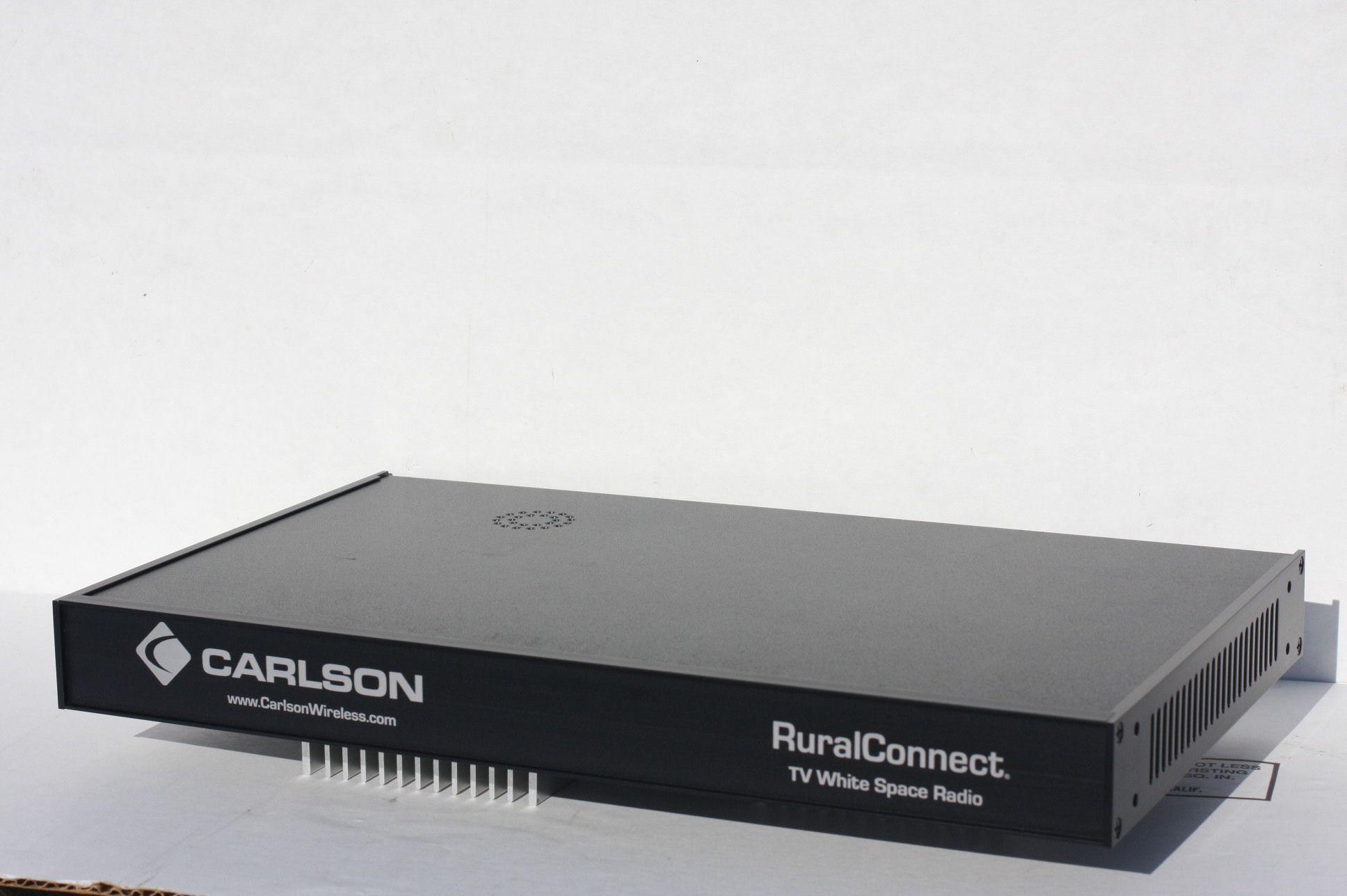
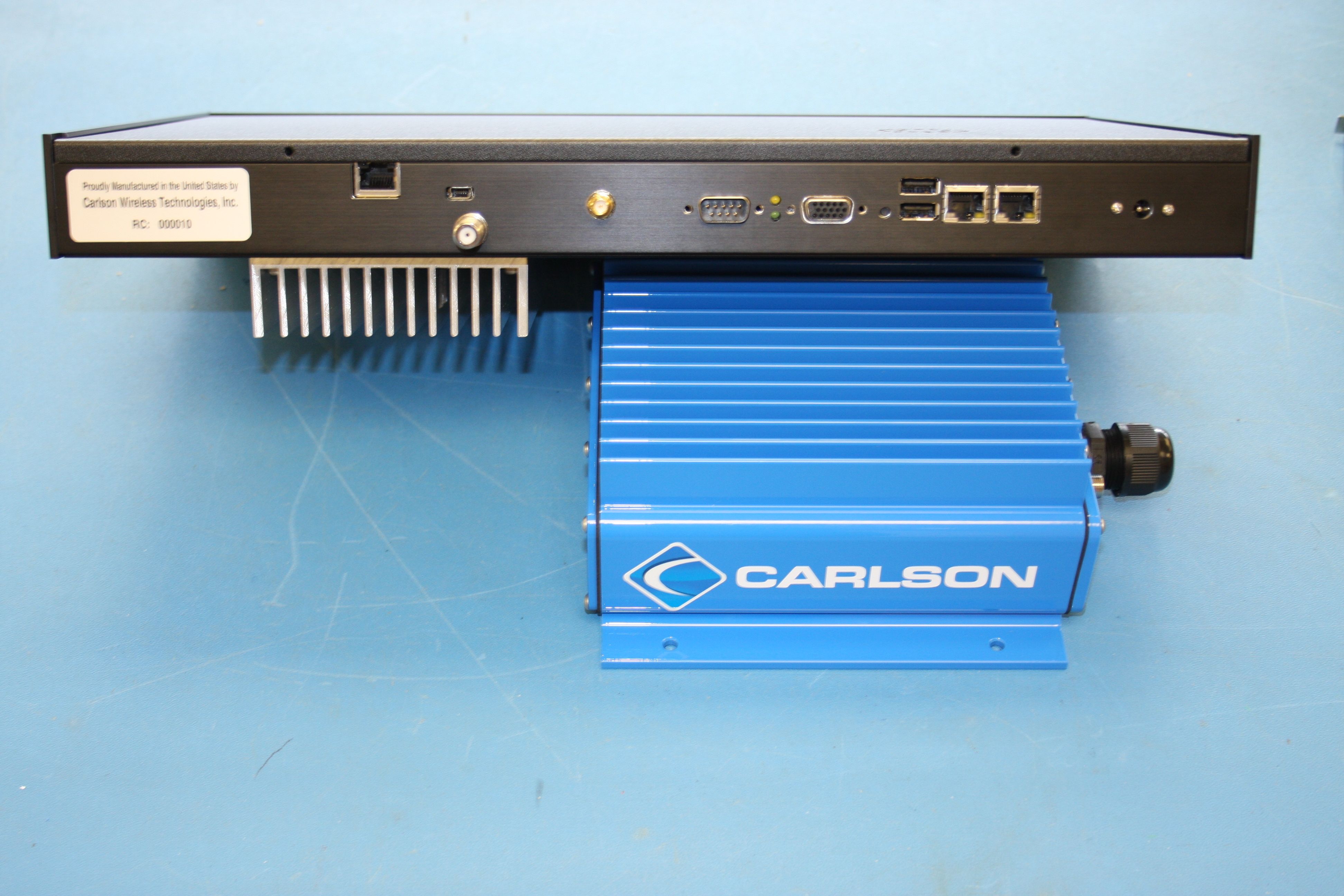
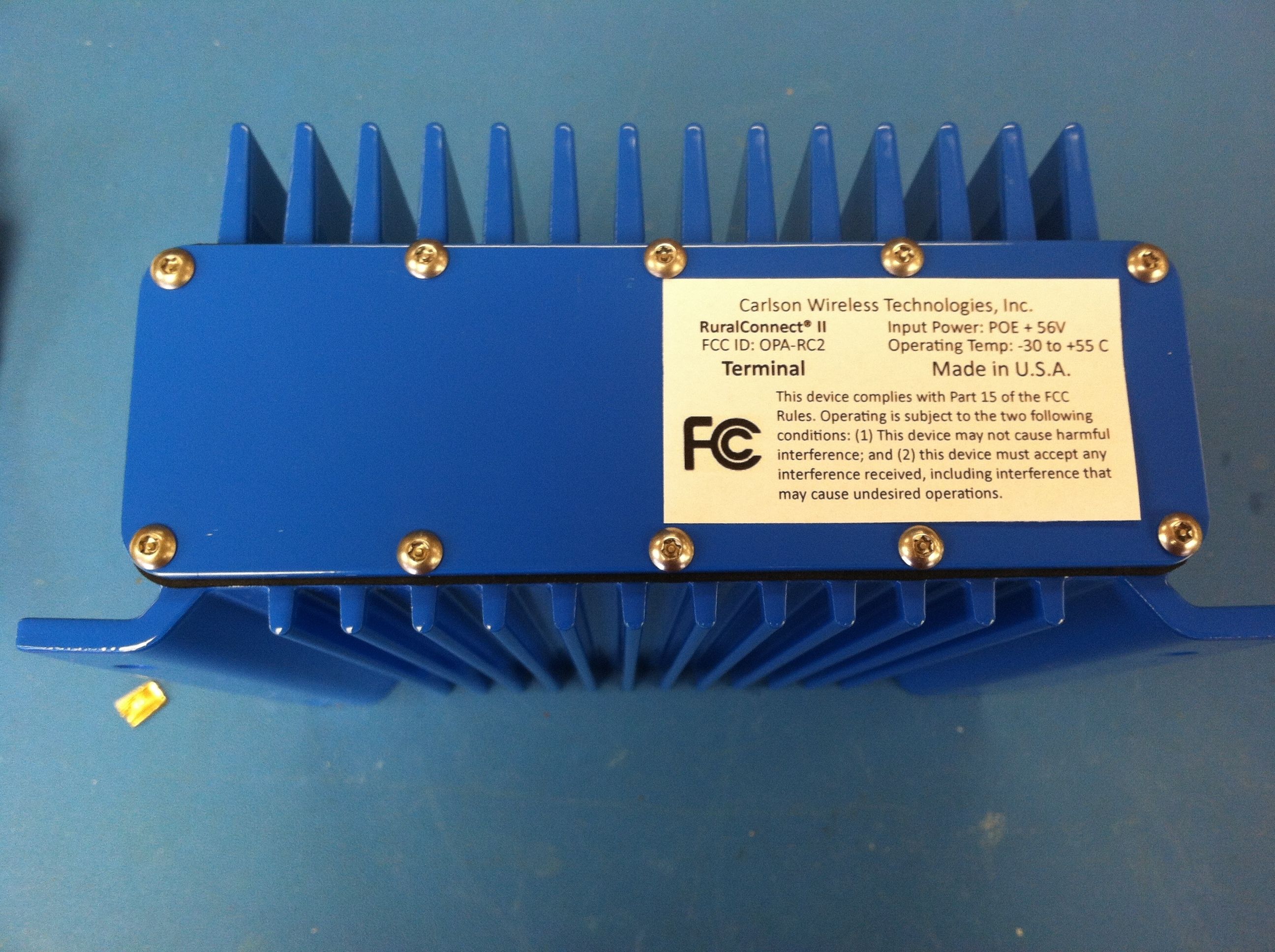
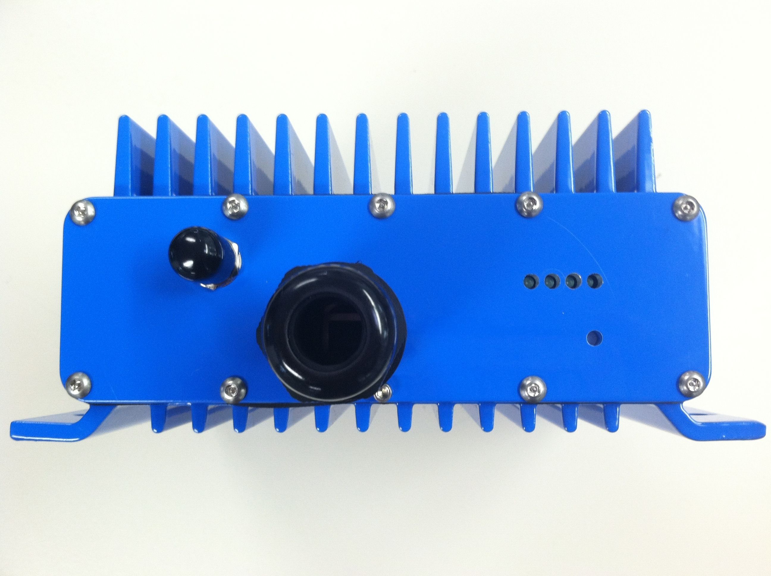
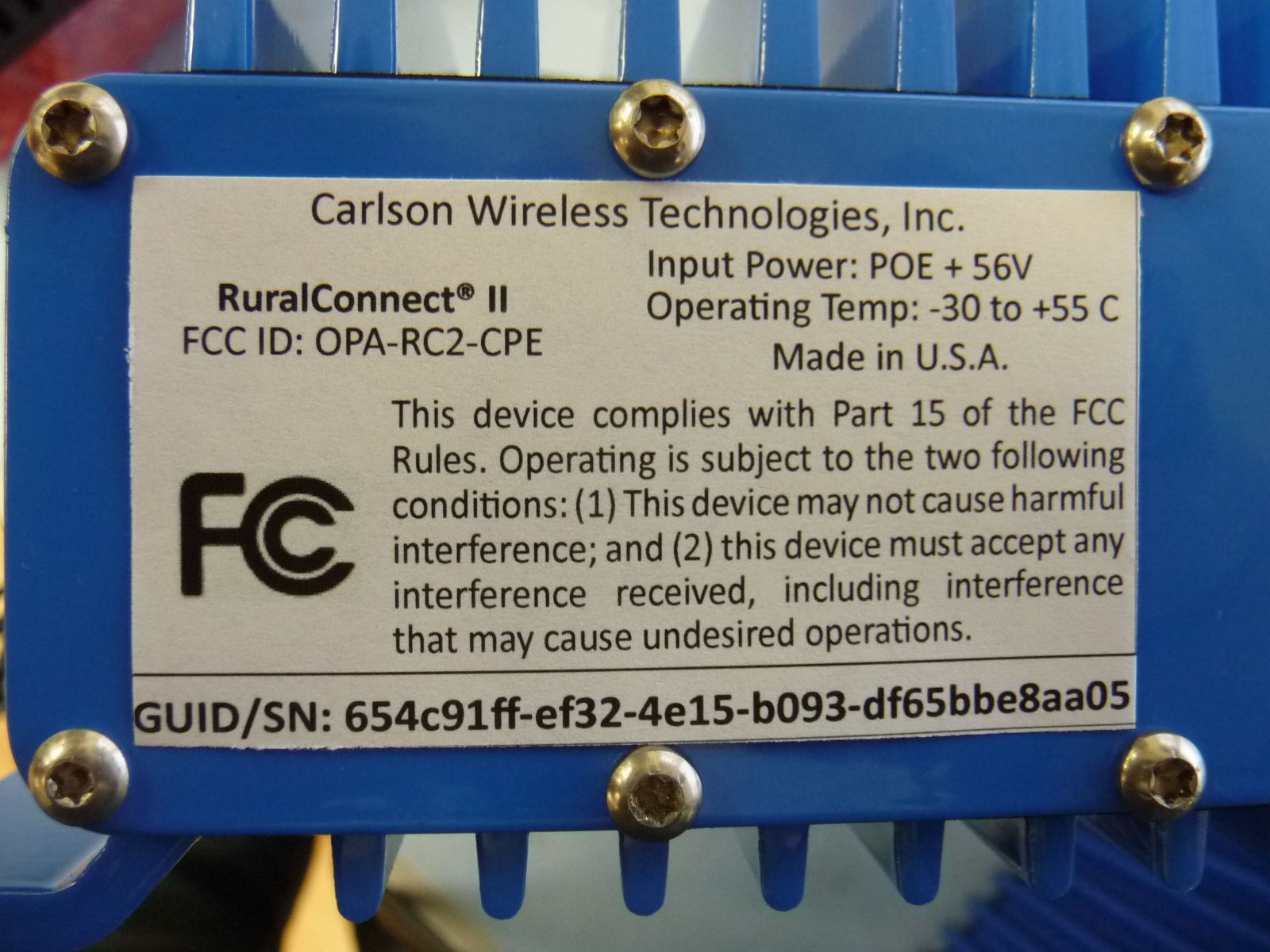
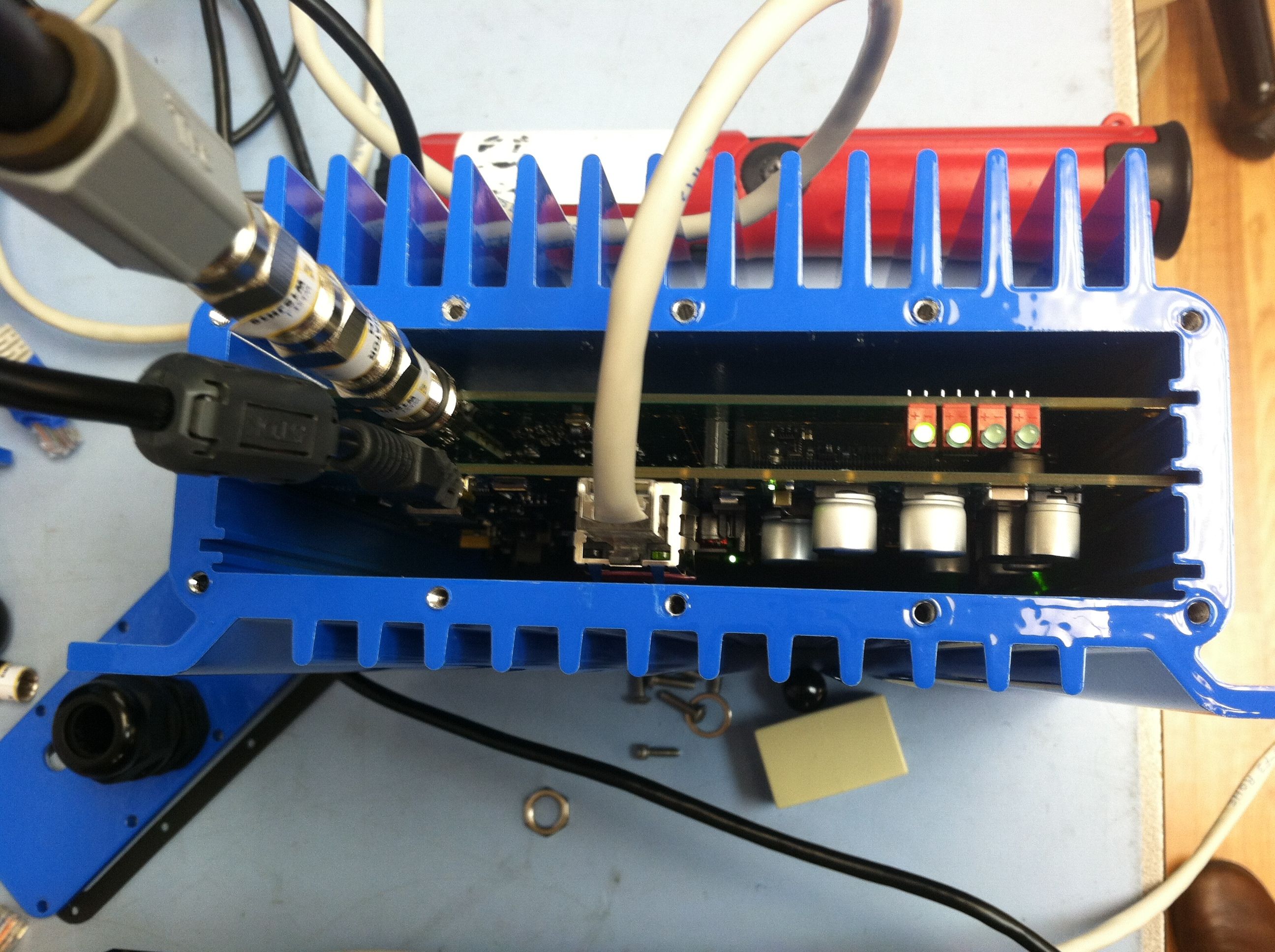
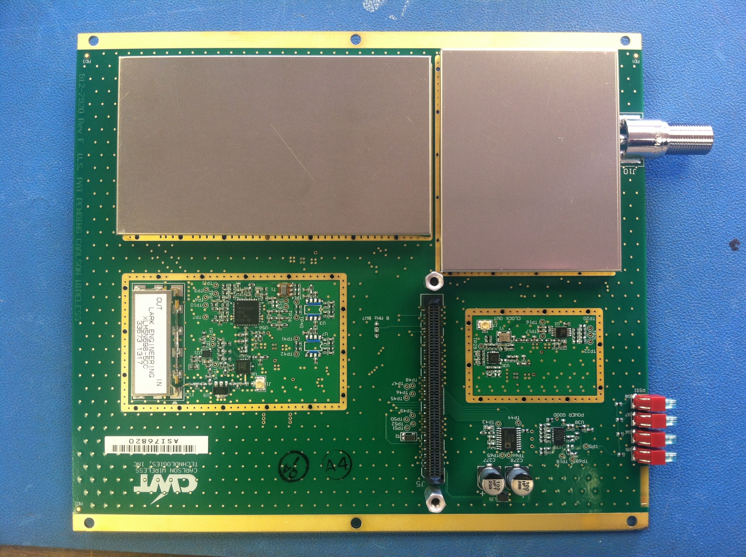
Powerline conducted test setup photo 1 Powerline conducted setup photo 1 Powerline conducted test setup photo #2 Radiated emissions test setup 1 Radiated emissions test setup 2 Radiated test setup photo #1 Radiated test setup photo #2 External photo 1 External photo 2 External photo 3 External photo 4 External 5 External 6 External photo 7
Contact Information
Applicant
James R. Carlson(CEO)
Technical Contact
Carlson Wireless Inc.James R. Carlson
[email protected](800)8342076
2700 Foster Avenue · Arcata, California · United States
Non-Technical Contact
Carlson Wireless Inc.James R. Carlson
[email protected](800)8342076
Test Firm
Timco Engineering, Inc.Bruno Clavier
Technical Specifications
| # | Rule Parts | Frequency Range | Power Output | Emission | Tolerance |
|---|---|---|---|---|---|
| 2 | 15H | 623 MHz - 695 MHz | 199.52 mW | 6M00G1D | 50 ppm |
Other Applications from Carlson Wireless Technologies Inc

OPA-RC2-BS
Dec 12, 2013White Space Broadband Radio
Equipment Class
WGF - White Space Device with Geo-location- Fixed
OPA-TB59
Jul 26, 2011Network Transmission Equipment
Equipment Class
TNB - Licensed Non-Broadcast Station Transmitter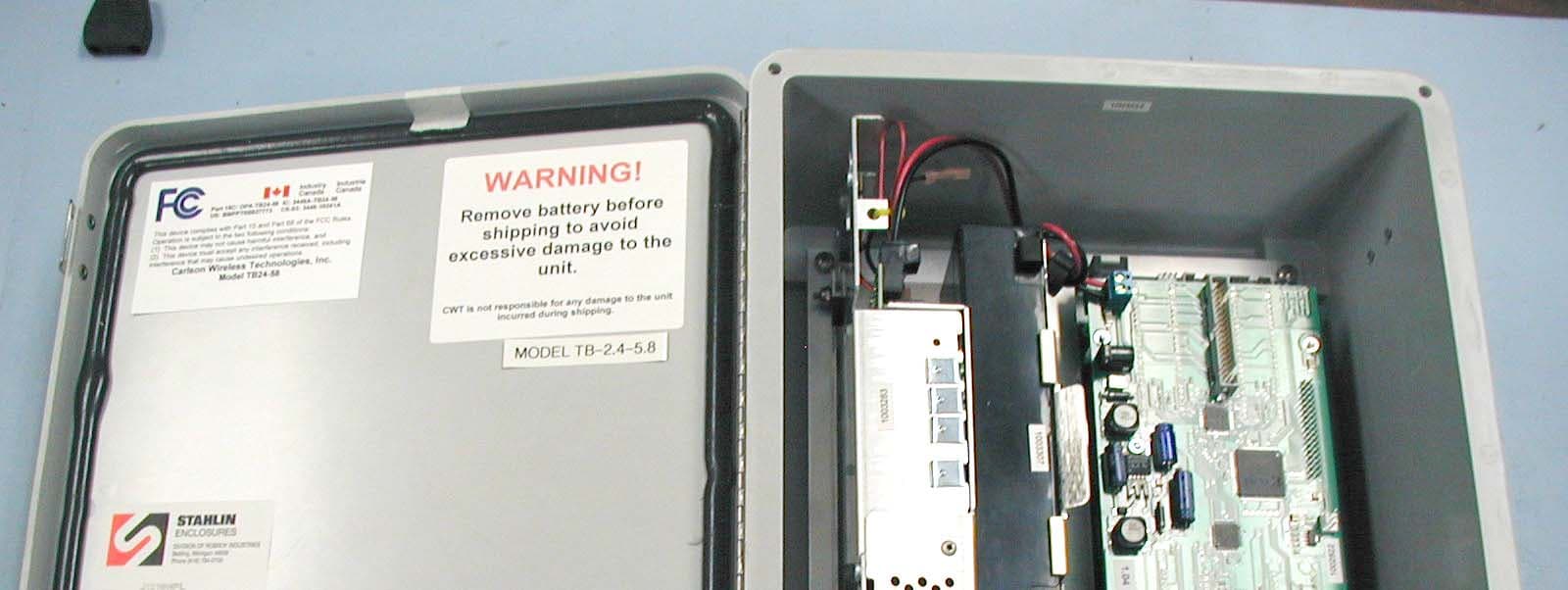
OPA-TB24-58
Jan 16, 2006Trailblazer 2.4 � 5.8
Equipment Class
DTS - Digital Transmission System
OPA-TB49
Jan 13, 2006Trailblazer TB 4.9
Equipment Class
TNB - Licensed Non-Broadcast Station Transmitter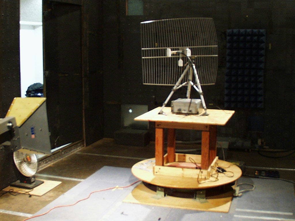
OPA-FT-512
Dec 19, 2002FT-512 Trailblazer Multifunctional Digital Radio
Equipment Class
DTS - Digital Transmission System