OPK-S503BLUETOOTH STEREO HEADSET
Shenzhen Kemei Wireless Communication Co., Ltd.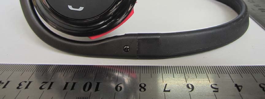
Click to zoom
Application Details
- Equipment Class
- DTS - Digital Transmission System
- Date of Grant
- Sep 05, 2012
- Application Purpose
- Original Equipment
- Date of Application
- Sep 05, 2012
- Equipment Note
- BLUETOOTH STEREO HEADSET
- Frequency Range
- 2402.00000000 - 2480.00000000
- Country
- China
Documents & Files
Document Text
Text extracted from the exhibit documents filed with the FCC. Open a document above to read the original.
Users Manual
4
External Photos
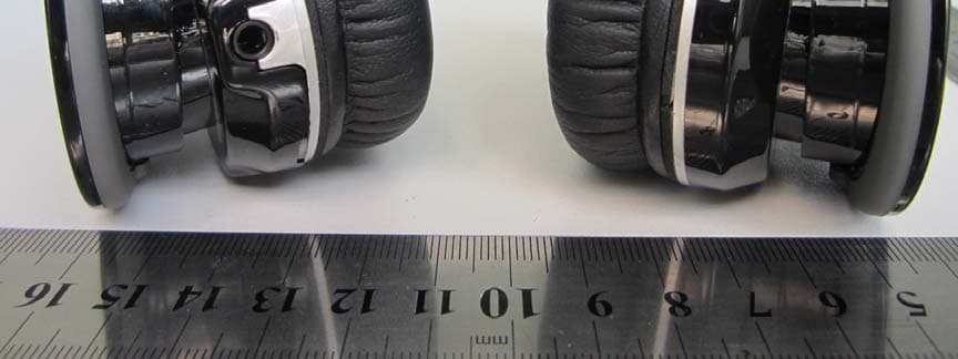
External Photos
ID Label/Location Info
FCC ID: OPK-S503 Label Label Location FCC ID Label Location
Internal Photos
Internal Photos
Test Report
SZ12080056W04 Page 2 of 36 DIRECTORY 1. GENERAL INFORMATION .................................................................................................... 3 1.1. EUT Description ....................................................................................................................... 3 1.2. Test Standards and Results ........................................................................................................ 4 1.3. Facilities and Accreditations ..................................................................................................... 5 2. 47 CFR PART 15C REQUIREMENTS .................................................................................... 6 2.1. Peak Output Power.................................................................................................................... 6 2.2. Average power .......................................................................................................................... 9 2.3. 6dB Bandwidth ....................................................................................................................... 10 2.4. 99% Bandwidth ....................................................................................................................... 13 2.5. Conducted Spurious Emissions ............................................................................................... 15 2.6. Power spectral density (PSD) ................................................................................................. 17 2.7. Band Edge ............................................................................................................................... 20 2.8. Conducted Emission ............................................................................................................... 24 2.9. Radiated Emission................................................................................................................... 27 Change History Issue Date Reason for change 1.0 Aug 31, 2012 First edition SZ12080056W04 Page 3 of 36 1. General Information 1.1. EUT Description EUT Type ............................. : Bluetooth Stereo Headset Serial No. .............................. : (n.a, marked #1 by test site) Hardware Version ................. : REV 6 Software Version .................. : Applicant .............................. : Manufacturer ........................ : 1200807 Shenzhen Kemei Wireless communication Co., Ltd. F/2, Dapengche Building, Zerong industrial park, Huangmabu, Xixiang, Baoan, Shenzhen, Guangdong 518000 China Shenzhen Kemei Wireless communication Co., Ltd. F/2, Dapengche Building, Zerong industrial park, Huangmabu, Xixiang, Baoan, Shenzhen, Guangdong Frequency Range .................. : The frequency range used is 2402MHz - 2480MHz (40 channels, at intervals of 2MHz); Modulation Type .................. : GFSK Antenna Type ........................ : PCB Antenna Antenna Gain ........................ : 0dBi Note 1: The EUT is Bluetooth Stereo Headset, it contains Bluetooth 2.1 EDR, Bluetooth 4.0 LE Dual Module operating at 2.4GHz ISM band; the frequencies allocated for the Bluetooth Module is F(MHz)=2402+2*n (0<=n<=39). The lowest, middle, highest channel numbers of the Bluetooth Module used and tested in this report are separately 0 (2402MHz), 19 (2440MHz) and 39 (2480MHz). Note 2: For a more detailed description, please refer to Specification or User’s Manual supplied by the applicant and/or manufacturer. SZ12080056W04 Page 4 of 36 1.2. Test Standards and Results The objective of the report is to perform testing according to 47 CFR Part 15 Subpart C (2.4GHz ISM band radiators) for the EUT FCC ID Certification: No. Identity Document Title 1 47 CFR Part 15 (10-1-09 Edition) Radio Frequency Devices Test detailed items/section required by FCC rules and results are as below: No. Section Description Result 1 15.247(a) Number of Hopping Frequency (n.a) 2 15.247(b) Peak Output Power PASS 3 15.247(b) Average Power PASS 4 15.247(a) 6dB Bandwidth PASS 5 15.247(a) 99% Bandwidth PASS 6 15.247(a) Carrier Frequency Separation (n.a) 7 15.247(a) Time of Occupancy (Dwell time) (n.a) 8 15.247(c) Conducted Spurious Emission PASS 9 15.247(c) Band Edge PASS 10 15.207 Conducted Emission PASS 11 15.209 15.247(c) Radiated Emission PASS 12 15.247(d) Power spectral density (PSD) PASS The tests of Conducted Emission and Radiated Emission were performed according to the method of measurements prescribed in ANSI C63.4 2009. These RF tests were performed according to the method of measurements prescribed in KBD558074. SZ12080056W04 Page 5 of 36 1.3. Facilities and Accreditations 1.3.1. Facilities Shenzhen Morlab Communications Technology Co., Ltd. Morlab Laboratory is a testing organization accredited by China National Accreditation Service for Conformity Assessment (CNAS) according to ISO/IEC 17025. The accreditation certificate number is L3572. All measurement facilities used to collect the measurement data are located at FL.3, Building a, FeiYang Science Park, No.8 LongChang Road, Block 67, BaoAn District, ShenZhen, GuangDong Province, P. R. China. The test site is constructed in conformance with the requirements of ANSI C63.7, ANSI C63.4 and CISPR Publication 22; the FCC registration number is 741109. 1.3.2. Test Environment Conditions During the measurement, the environmental conditions were within the listed ranges: Temperature (°C): 15 - 35 Relative Humidity (%): 30 -60 Atmospheric Pressure (kPa): 86-106 SZ12080056W04 Page 6 of 36 2. 47 CFR Part 15C Requirements 2.1. Peak Output Power 2.1.1. Requirement According to FCC section 15.247(b)(3), For systems using digital modulation in the 902-928 MHz, 2400-2483.5 MHz, and 5725-5850 MHz bands: The maximum peak conducted output power of the intentional radiator shall not exceed1 Watt. 2.1.2. Test Description The measured output power was calculated by the reading of the spectrum analyzer and calibration. A. Test Setup: The EUT (Equipment unde…
Text truncated - open the document above for the full version.
Test Setup Photos
Test Setup Photos 1. CE 2.RE 3. CSE
Contact Information
Applicant
Kexue Bai(CEO)
Test Firm
Shenzhen Morlab Communications Technology Co.,LtdShu Luan
Technical Specifications
| # | Rule Parts | Frequency Range | Power Output |
|---|---|---|---|
| 1 | 15C | 2.40 GHz - 2.48 GHz | 3.00 mW |
Other Applications from Shenzhen Kemei Wireless Communication Co., Ltd.
OPK-S680
Sep 02, 2012BLUETOOTH STEREO HEADSET
Equipment Class
DSS - Part 15 Spread Spectrum Transmitter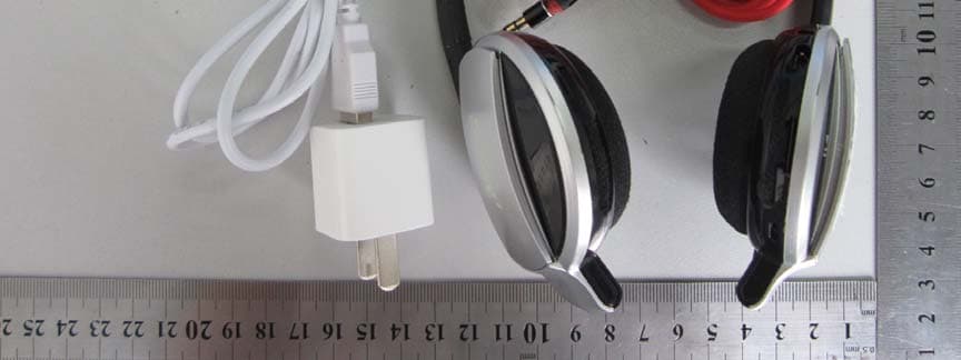
OPK-S501
Sep 02, 2012BLUETOOTH STEREO HEADSET
Equipment Class
DTS - Digital Transmission System