OPOSSOHT300VHTCOMOHT Vehicle
Shinko Electric Co Ltd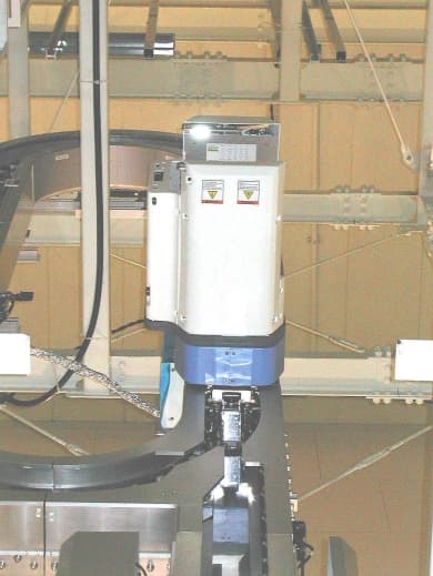
Click to zoom
Application Details
- Equipment Class
- DCD - Part 15 Low Power Transmitter Below 1705 kHz
- Date of Grant
- May 26, 2002
- Application Purpose
- Original Equipment
- Date of Application
- May 26, 2002
- Equipment Note
- OHT Vehicle
- Frequency Range
- 0.35325000 - 0.35325000
- Company
- Shinko Electric Co Ltd
- Country
- Japan
Documents & Files
Document Text
Text extracted from the exhibit documents filed with the FCC. Open a document above to read the original.
Users Manual
SHINKO ELECTRIC CO., LTD YTEM-3518 Rev.1 Operation Manual 1 SSOHT-300 System Vehicle Operation Manual S-NEW02-0029 Revision 0 Apr. 26, 2002 The information furnished herein by SHINKO ELECTRIC CO.,LTD. is proprietary and confidential to SHINKO ELECTRIC CO.,LTD. personnel and is not to be duplicated, published, or disclosed to any third party in whole or in part without permission from SHINKO ELECTRIC CO.,LTD. Copyright© 1999 SHINKO ELECTRIC CO., LTD. ALL RIGHTS RESERVED. Unpublished rights reserved under the copyright laws of the United States. 2 SHINKO ELECTRIC CO., LTD S-NEW02-0029 Rev.1 Operation Manual The information contained herein is provided pursuant to the terms of a License, Non- disclosure and/or Confidentiality Agreement and co nstitutes and contains valuable proprietary information and trade secrets of SHINKO ELECTRIC CO., LTD. embodying substantial creative efforts and co nfidential information, ideas, and expressio ns. Accordingly, strict compliance with the terms and conditions of the governing Agreement, including, witho ut limitatio n, all restrictions o n use and disclosure, is required as a co ndition to the use of the information co ntained herein. Except as may be permitted in the applicable Agreement, the information herein may not be reproduced or disclosed in whole or in part. Restricted Rights Legend Use, duplicatio n, or disclosure by the Government is subject to restrictions as set forth in subparagraph <c> (1) (ii) of the Rights in Technical Data and Computer Software clause at DFARS 252.277-7013 SHINKO ELECTRIC CO., LTD. 100 Takegahana, Ise city, Mie prefecture, 516-8550, Japan Telephone: +81-596-36-3180 Facsimile: +81-596-36-3974 Contents SHINKO ELECTRIC CO., LTD S-NEW02-0029 Rev.1 Operation Manual 3 Contents 1.SSOHT-300 System and Vehicle Overview................ 5 1.1.Purpose of the SSOHT-300 ............................................... 5 1.2.SSOHT-300 System ........................................................... 5 1.3.Non-Contact Power Supply............................................... 8 1.4.FCC (Federal Communications Commission) Regulation (provisional) .............................................................. 8 1.5.Notice and Warning of FCC (provisional)......................... 9 2.OHT Vehicle ............................................................... 11 2.1.External Appearance of the OHT Vehicle ....................... 11 2.2.Parts Name and Function................................................ 12 2.2.1. Vehicle Body ............................................................................... 12 2.2.2. Bumper........................................................................................ 12 2.2.3. Vehicle Stop Switch .................................................................... 12 2.2.4. Fall Prevention Mechanism........................................................ 12 2.2.5. Front Monitor Sensor.................................................................. 12 2.2.6. Display Panel and Operation Panel............................................ 13 3.Specifications ............................................................ 15 3.1.General Specifications .................................................... 15 3.1.1. Wafer Carrier ............................................................................... 15 3.1.2. Transport Unit ............................................................................. 15 3.1.3. Environmental Condition (Needs a review!! )............................. 15 3.2.Basic Technology Specifications.................................... 16 4.Emgergency Stop Procedures ................................. 17 4.1.EMO (Emergency Off)...................................................... 17 4.1.1. Location of EMO ......................................................................... 17 4.1.2. EMO Operation............................................................................ 17 4.2.The Stop Button on the Vehicle ...................................... 17 4.2.1. The Vehicle Stop (emergency stop) Button on the Vehicle........ 17 5.Operation ................................................................... 19 5.1.Vehicle Operation Mode .................................................. 19 5.2.Auto mode........................................................................ 19 5.3.Local mode ...................................................................... 20 Contents 4 SHINKO ELECTRIC CO., LTD S-NEW02-0029 Rev.1 Operation Manual 6.Teaching..................................................................... 21 6.1.References ....................................................................... 21 6.2.Two Types of Teaching .................................................... 21 6.3.Remote Control Box ........................................................ 22 7.Preparation ................................................................ 23 7.1.Preparation of the OHT Vehicle ...................................... 23 7.2.Preparation of the Remote Control Box ......................... 23 7.3.Registration of a Vehicle F Number................................ 23 7.3.1. Confirmation of the DIP Switches of the Remote Control Switches ..................................................................................... 24 7.3.2. Registration of F Number ........................................................... 24 8.Remote Control Box Position................................... 25 9.Remote Control Operation........................................ 27 9.1.Remote Control Operation List ....................................... 27 9.2.Status Transition during the Remote Control Operation .................................................................................... 28 9.3.Basic Button Operation ................................................... 29 9.4.Remote Control Operation Button Assignment ............. 29 9.4.1. Function Button .............................................…
Text truncated - open the document above for the full version.
Cover Letter(s)
A- PEX INTERNATIONAL CO., LTD. •EMC HEAD OFFICE DIVISION 4383-326 Asama-cho, Ise-shi, Mie-ken 516-0021 Japan TEL:0596-24-8116 / FAX:0596-24-8124 Date: Mary 23, 2002 Re : Shinko Electric Co., Ltd. FCC ID : OPOSSOHT300VHTCOM Dear Mr. Timothy R. Johnson, Please find the following replies to your comments dated May 15, 2002; 1) Please find the Declaration of Block Diagram. 2) Please find re-submitted external photos of this equipment. 3) This is composite device subject to part 15 Subpart B Class A (Digital Device) and Part 15 Subpart C (Int entional Radiator). 4) Please find re-submitted photo of set up. 5) This was tested on the turn table as floor standing. 6) The AC mains of this equipment (VHT5-1: DC 24V / 3ASSYC807901: DC 5V) have not been provided from host equipment which is installed i n factory, and also have never connected to public AC power line directly. The two connections to 120VAC/60Hz in Page 5 of our test report are for exclusive use of the measurement equipment. 7) Please find Page 9 in Manual. 8) The ferrite core shown on page 5 in the test report is installed for EMI suppression. The same ferrite core is also installed to the mass produced equipment and then sold. 9) This test was enforced by rotating loop antenna. 10) Please find the submitted Data of Carrier and Spurious Test and Duty Cycle. 11) Please find re-submitted the revised test report. Kanako Sanda (Ms.) A-Pex Int ernational Co., Ltd.
Cover Letter(s)
American Telecommunications Certification Body Inc. 6731 Whittier Ave, McLean, VA 22101 May 15, 2002 RE: Shinko Electric Co. Ltd. FCC ID: OPOSSOHT300VHTCOM After a review of the submitted information, I have a few comments on the above referenced Application. 1) Please provide a block diagram that includes the frequencies as specified in CFR 2.1033(a)(5). 2) The External Photographs do not give a good indication what this device is. Please provide additional photographs that give a better idea what this device is. 3) This appears to be a complex system in which different parts of the system will require separate certification. It also appears that parts of this system may already be approved. Please update the 731 sections 7 & 8 as applicable. 4) The test setup photographs are very dark. Are lighter ones available? 5) Was the device placed on a turntable as floor standing or table top equipment? 6) The EUT appears to receive its power from a special track, yet the block diagram (page 5 of 10) shows 2 connections to 120 VAC/60 Hz. This is not expected given the block diagram and technical description and the test report on pages 4 of 10 state that the EUT does not have AC mains. Please explain. Give that the vehicle travels, if it does require 120 VAC/60 Hz as well, how does it obtain this and where is the conducted data? 7) The users manual should include the statements specified by 15.105 (a). Please correct. 8) Was the ferrite core shown on page 5 of 10 already installed within the EUT, or was it a modification that was added? 9) The test report states that the loop antenna was placed in the horizontal and vertical planes. It must also be rotated about the horizontal and vertical axis during testing. Was this performed? 10) According to the test report, much of the data given below 490 kHz is give for an average detector. As specified by 15.35(b), there is also a limit to the peak emissions (20 dB above the average limit), however peak measurements were not provided. Please provide additional peak data if available or as an alternative provide information regarding the measured difference between the average and peak measurements for these frequencies. 11) FYI, The limit for 443.16 kHz on page A2 is incorrect. Timothy R. Johnson Examining Engineer mailto: [email protected] The items indicated above must be submitted before processing can continue on the above referenced application. Failure to provide the requested information may result in application termination. Correspondence should be considered part of the permanent submission and may be viewed from the Internet after a Grant of Equipment Authorization is issued. Please do not respond to this correspondence using the email reply button. In order for your response to be processed expeditiously, you must submit your documents through the AmericanTCB.com website. Also, please note that partial responses increase processing time and should not be submitted. Any questions about the content of this correspondence should be directed to the sender.
External Photos
SHINKO ELECTRIC CO., LTD. FCC ID: OPOSSOHT300VHTCOM Front of EUT (OHT Vehicle) SHINKO ELECTRIC CO., LTD. FCC ID: OPOSSOHT300VHTCOM Back of EUT (OHT Vehicle) SHINKO ELECTRIC CO., LTD. FCC ID: OPOSSOHT300VHTCOM Right side of EUT (OHT Vehicle) SHINKO ELECTRIC CO., LTD. FCC ID: OPOSSOHT300VHTCOM Left of EU T (OH T Vehicle)
Internal Photos
SHINKO ELECTRIC CO., LTD. FCC ID: OPOSSOHT300VHTCOM SHINKO ELECTRIC CO., LTD. FCC ID: OPOSSOHT300VHTCOM SHINKO ELECTRIC CO., LTD. FCC ID: OPOSSOHT300VHTCOM
Operational Description
Production Description 1. The product that SHINKO applies FCC part15 subpart C. SHINKO is applied about the communication system of SSOHT-300 vehicle, which is the transportation system in such as semiconductor manufacturing. 2. General It is stated about the outline of SSOHT-300 transportation system easily. The example of the typical SSOHT-300 system is shown in the fig. 1. - SSOHT-300 transportation system is used in clean room, and it does the carriage of the semiconductor product. - SSOHT-300 Vehicle is hung in track, and it runs. Then, vehicle can do the control of divergence joining by itself. Vehicle has hoist mechanism, and it can load and unload a baggage such as FOUP in Load Port of the manufacture equipment. - The power of Vehicle is supplied by using the non-contact power supply technology in the frequency of 8.66kHz. -OHVC gives vehicle a carriage order, and remote control does vehicles. -Communication with vehicle and OHVC (OHT Vehicle Controller) is done by piling up a communication signal to the electric power line. As for the frequency of the career, a transmitting signal is 300.75kHz and receiving signal is 353.25kHz. OHT Vehicle Enter-Inhibit Floodlight EMO OHVC (PC.) Power Source Panel Maintenance Lifer AC208V(3φ) Track AC120V(1φ) RS232C RS485 AC208V(3φ) CMC E-PLC (Maintenance Lifter Controller) Maintenance Lifter control Box About 400V,55A (8.66kHz) Fig.1 The example of the typical SSOHT-300 system 3. Communication system The communication of SSOHT-300 system has two kinds of the next. (1) Power line communication Communication between OHVC (OHT Vehicle Controller) installed in the ground, and vehicle is done through Power-line-communication. Then, a communication such as a carriage order is done. (2) Induction line communication Communication between vehicles, which is done through Induction line in the divergence and the joining. It is done to decide the order of priority for vehicle to move forward. 3.1 The construction of the communication system The construction of the communication system is shown in the fig. 2. M-COM2 Communication board OHT-CPU CPU board NBV-BC BV-BM2A CMC : Communication Modem Controller Power Supply Unit Other Vehicle OHVC OHT Vehicle Controller SSOHT-300 Vehicle Transformer (Power line) Transformer ( Induction line) 88.8kHz 300.75kHz 353.25kHz 8.66kHz 300.75kHz 353.25kHz Induction line Electric power line FCC Part15 Subpart C is applicable. Fig.2 The construction of the communication system FCC a pproved M-COM2: The communication board installed in vehicle. Two kinds of communication are done by the control of the OHT-CPU. Using frequency -Power line communication (Adoption of Frequency Shift Keying Method) Receive: Carrier frequency 300.75kHz (Modulation frequency 285.7kHz and 315.8kHz) Transmit: Carrier frequency 353.25kHz (Modulation frequency 342.9kHz and 363.6kHz) -Induction line communication (Adoption of On Off Keying Method) 88.8kHz OHT-CPU: The main controller board of vehicle, which does the control of all the movements. Clock frequency is 133MHz. CMC(Communication Modem Controller): It is power line communication device on the ground side. It has already been approved officially by FCC. 3.2 The movement of M-COM2 (1) Power line communication -It does demodulation of the receiving signal and moderation of the transmitting signal. - There are a transformer for the reception and a transformer for the transmission, and a communication signal is piled up to the electric power line through the transformer and received. (2) Induction line communication - A signal is transmitted and received by the order of the OHT-CPU. -M-COM2 outputs the detection signal of one bit in the OHT-CPU when the existence of the signal which other vehicle transmitted. - A Induction line is installed on both sides of the track. Therefore one transformer and circuit are each right and left, and they are equal. - It can be changed if one transformer is used for the reception or it is used for the transmission. -A left-right coil is combined with the loop line, and it can watch each other's transmitting signal. Then, a trouble such as the breakage of the transformer can be diagnosed.
Test Report
A-PEX INTERNATIONAL CO., LTD. YOKOWA NO.1 OPEN SITE Company: Shinko Electric Co.,Ltd.Report No: 22HE0104-YW Equipment: OHT System (Transceiver)Regulation: FCC 15.209(a) Model: SSOHT-300Test Distance: 3m Power: DC 24.0VDate: 2002/4/8 Mode: TransmittingReviced Date : 2002/5/17 Fundamental : 88.88kHzFCC ID: OPOSSOHT300VHTCO M Serial No.: sample No.1 Temperature : 20deg.C Humidity: 69% ENGINEER : Seigo Kakehi Frequenc y Rage :9kHz-90kHz and 110kHz-490kHz PK Data No. FREQ ANT AV READINGANT ATTE NCABLEAMPDutyRESULTLIMITMARGIN TYPE 0 deg90 deg FactorLOSS GAIN Factor0deg90deg (PK)0deg90deg [kHz][dB][dB][dB][dB][dB][dBuV/m] 188.44 BB74.874.720.10.00.125.020.090.089.9128.738.738.8 2177.76 BB71.666.520.10.00.127.620.084.279.1122.638.443.5 3283.18 BB61.364.620.10.00.228.320.073.376.6118.645.342.0 4358.10 BB56.662.520.10.00.228.720.068.274.1116.548.342.4 5443.16 BB33.833.720.10.00.228.920.045.245.1114.669.469.5 REMARKS CALCULATION : RESULT = READING + ANT Factor + ATTEN + Cable Loss - AMP Gain + *Duty Factor *Duty Factor : 20dB(Duty 10%) [dBuV][dBuV/m][dB] Data of Carrier and Spurious Test(9kHz to 30MHz) A-PEX INTERNATIONAL CO., LTD. YOKOWA NO.1 OPEN SITE Company: Shinko Electric Co.,Ltd.Report No: 22HE0104-YW Equipment: OHT System (Transceiver)Regulation: FCC 15.209(a) Model: SSOHT-300Test Distance: 3m Power: DC 24.0VDate: 2002/4/8 Mode: TransmittingFCC ID: OPOSSOHT300VHTCO M Fundamental : 353.25kHz Serial No.: sample No.1 Temperature : 20deg.C Humidity: 69% ENGINEER : Seigo Kakehi Frequenc y Rage :9kHz-90kHz and 110kHz-490kHz PK Data No. FREQANT AV READINGANT ATTE NCABLEAMPDutyRESULTLIMITMARGIN TYPE 0 deg90 deg FactorLOSS GAIN Factor0deg90deg (PK)0deg90deg [kHz][dBuV] [dBuV][dB][dB][dB][dB][dB][dBuV/m] 1378.81 BB70.181.420.10.00.228.712.073.785.0116.042.331.0 REMARKS CALCULATION : RESULT = READING + ANT Factor + ATTEN + Cable Loss - AMP Gain + *Duty Factor *Duty Factor : 12dB(Duty 25%) [dBuV/m][dB] Data of Carrier and Spurious Test(9kHz to 30MHz)
Test Report
Test report No.: 22HE0104-YW FCC ID: OPOSSOHT300VHTCOM Issued date: May 22, 2002 A-pex International Co., Ltd. YOKOWA LAB. 108 Yokowa-cho, Ise-shi, Mie-ken 516-1106 JAPAN Telephone: int +81 596 39 1485 Facsimile: int +81 596 39 0232MF060b(22.05.01) Duty Cycle 10%(88.8kHz Transmitting) Duty Cycle 25%(353.25kHz Transmitting)
Test Report
Test report No.: 22HE0104-YW FCC ID: OPOSSOHT300VHTCOM Page: 1 of 10 Issued date: May 8, 2002 A-pex International Co., Ltd. YOKOWA LAB. 108 Yokowa-cho, Ise-shi, Mie-ken 516-1106 JAPAN Telephone: int +81 596 39 1485 Facsimile: int +81 596 39 0232MF060b(22.05.01) EMI TEST REPORT Test Report No. : 22HE0104-YW Applicant:Shinko Electric Co., Ltd. Type of Equipment:SELOHT SHINKO OHT SYSTEM Model No.:SSOHT-300 FCC ID:OPOSSOHT300VHTCOM Test standard:FCC Part 15 Subpart C Section 15.209 FCC Part 15 Subpart B Section 15.109(b) Test Result:Complied 1. This test report shall not be reproduced in full or partial, without the written approval of A-Pex International Co., Ltd. 2. The results in this report apply only to the sample tested. 3. This equipment is in compliance with above regulation. We hereby certify that the data contains a true representation of the EMC profile. 4. The test results in this report are traceable to the national or international standards. 5. This test report does not constitute an endorsement by NIST/NVLAP or U.S. Government. Date of test: April 8 and 9, 2002 Tested by: Seigo kakehi Approved by: Kazutoyo Nakanishi Site Operation Manager of EMC section Test report No.: 22HE0104-YW FCC ID: OPOSSOHT300VHTCOM Page: 2 of 10 Issued date: May 8, 2002 A-pex International Co., Ltd. YOKOWA LAB. 108 Yokowa-cho, Ise-shi, Mie-ken 516-1106 JAPAN Telephone : int +81 596 39 1485 Facsimile : int +81 596 39 0232 CONTENTS PAGE SECTION 1: Client information 3 SECTION 2: Equipment under test (E.U.T.) 3 SECTION 3: Test specification, methods & procedures 4 SECTION 4: Operation of E.U.T. during testing 4 SECTION 5: Summary of test results 6 SECTION 6: Radiated emission 7 APPENDIX 1: Photographs of test setup 8 APPENDIX 2:Test instruments 8 APPENDIX 3: Data of EMI test 8 Test report No.: 22HE0104-YW FCC ID: OPOSSOHT300VHTCOM Page: 3 of 10 Issued date: May 8, 2002 A-pex International Co., Ltd. YOKOWA LAB. 108 Yokowa-cho, Ise-shi, Mie-ken 516-1106 JAPAN Telephone : int +81 596 39 1485 Facsimile : int +81 596 39 0232 SECTION 1: Client information Company name: Shinko Electric Co., Ltd. Address: 100 Takegahana-cho , Ise-shi , Mie 516-8550 , Japan Telephone Number: +81-596-36-2335 Facsimile Number: +81-596-36-2162 Contact Person: Mr.T.Kitano SECTION 2: Equipment under test (E.U.T.) 2.1Identification of E.U.T. Type of Equipment: SELOHT SHINKO OHT SYSTEM Model No.: SSOHT-300 (VHT5-1 + 3ASSYC807901) Sample No.: 1 Condition of EUT: Production model Rating: DC 24V , DC 5V , +12V Country of Manufacture: Japan Receipt Date of Sample: April 8, 2002 2.2Product Description Model: VHT5-1 / SSOHT-300(VHT5-1:Vehicle / SSOHT-300:System)(referred to as the EUT in this report) is a SELOHT SHINKO OHT SYSTEM. This equipment is a FCC part 15 subpart B class A digital device with RF unit lorded. The specification is as follows; Communication unit’s carrier frequency (Intentional Radiators): 88.8kHz (on off keying) : 353.25kHz (FSK) Communication unit’s main clock(Unintentional Radiators): 24MHz CPU clock(Unintentional Radiators): 133MHz Test report No.: 22HE0104-YW FCC ID: OPOSSOHT300VHTCOM Page: 4 of 10 Issued date: May 8, 2002 A-pex International Co., Ltd. YOKOWA LAB. 108 Yokowa-cho, Ise-shi, Mie-ken 516-1106 JAPAN Telephone : int +81 596 39 1485 Facsimile : int +81 596 39 0232 SECTION 3: Test specification, methods & procedures 3. 1Test Specification Test Specification: FCC Part 15 Subpart C Section 15.209 Title: FCC 47CFR Part15 Radio Frequency Device Subpart C Intentional Radiators Section 15.209 Radiated emission limits; general requirements Test Specification: FCC Part 15 Subpart B Section 15.109(b) Title: FCC 47CFR Part15 Radio Frequency Device Subpart B Unintentional Radiators 3.2Methods & Procedures No.ItemTest ProcedureSpecificationRemarks 1Radiated emissionANSI C63.4:2000 Section 15.109(b) Section 15.209(a) 3m/10m 2Conducted emissionANSI C63.4:2000 Section 15.107(b) Section 15.207(a) LISN These tests were performed without any deviations from test procedure excluding below additions or deviations. 3.3 Exclusion from standards No.ItemTest ProcedureSpecificationRemarks 2Conducted emissionANSI C63.4:2000 Section 15.107(b) Section 15.207(a) LISN The test is not applicable since the EUT does not have AC Mains. SECTION 4: Operation of E.U.T. during testing 4.1Operating Modes The EUT exercise program used during radiated and conducted testing was designed to exercise the various system components in a manner similar to typical use. The operating mode/system were as follows: Operation : Transmitting (88.8kHz and 353.25kHz *FCC Part15 subpart C) Branch Exchange Mode(Semaphore Mode *FCC Part15 subpart B) Vehicle is at the branch section for entrance coordination. Justification: The system was configured in typical fashion (as a customer would normally use it) for testing. Remarks: This is a compound equipment of FCC part 15 subpart B class A digital device and FCC part 15 subpart C Intentional radiators. The frequency from 9kHz to the maximum frequency 30MHz of intentional radiator including the tenth harmonic, measured as section 15.209 and the frequency over 30MHz measured as section 15.109. Test report No.: 22HE0104-YW FCC ID: OPOSSOHT300VHTCOM Page: 5 of 10 Issued date: May 8, 2002 A-pex International Co., Ltd. YOKOWA LAB. 108 Yokowa-cho, Ise-shi, Mie-ken 516-1106 JAPAN Telephone : int +81 596 39 1485 Facsimile : int +81 596 39 0232 4.2 Configuration and peripherals *Cabling was taken into consideration and test data was taken under worse case conditions. Description of EUT and Support equipment No.ItemModel numberSerial numberManufacturerRemarks A VehicleVHT5-1-SHINKOEUT B Communication Board (M-COM2) 3ASSYC807901-SHINKOEUT C Power SupplyPAB25-1TR30081818KIKUSUI- D Host (Vehicle Controller) --SHINKO- List of cables used No.NameLength (m)ShieldBackshell MaterialRemark 1 Interconnection Cable1.0Y Polyvinyl chloride - 2 Interconnection Cable1.0Y Polyvinyl chloride - 3 Interconnection Cable2.0Y Polyvinyl chloride - 4 P…
Text truncated - open the document above for the full version.
Test Setup Photos
SHINKO ELECTRIC CO., LTD. FCC ID: OPOSSOHT300VHTCOM Set up photo
Contact Information
Applicant
Hiroshi Fujii(General Manager, Quality Assurance Dept.)
Technical Contact
A-Pex International Co., Ltd.Keigo Kakehi
[email protected]+81-596-39-1485
108 Yokowa-cho · Ise-shi, Mie-ken · Japan
Non-Technical Contact
A-Pex International Co., Ltd.Kanako Sanda
[email protected]+81-596-24-8116
Test Firm
UL Japan, Inc.Kazunori Nishimura
Technical Specifications
| # | Rule Parts | Frequency Range | Power Output |
|---|---|---|---|
| 2 | 15C | 0.35325 MHz - 0.35325 MHz | - |
Other Applications from Shinko Electric Co Ltd
Feb 06, 2001
Equipment Class
DCD - Part 15 Low Power Transmitter Below 1705 kHzOPO199909010002
Feb 22, 2000DCD - Part 15 Low Power Transmitter Below 1705 kHz
Equipment Class
DCD - Part 15 Low Power Transmitter Below 1705 kHz
OPO199909010001
Dec 09, 1999Communication Modem Controller
Equipment Class
DCD - Part 15 Low Power Transmitter Below 1705 kHz