OQ3MAF900-60SRF Amplifier. M/N:MAF900-60S
Paradigm Wireless Systems Inc
Click to zoom
Application Details
- Equipment Class
- AMP - Amplifier
- Date of Grant
- Nov 15, 2001
- Application Purpose
- Original Equipment
- Date of Application
- Nov 15, 2001
- Equipment Note
- RF Amplifier. M/N:MAF900-60S
- Frequency Range
- 935.00000000 - 940.00000000
- Country
- United States
Documents & Files
Document Text
Text extracted from the exhibit documents filed with the FCC. Open a document above to read the original.
Users Manual
MAF 900-60S MULTI-CARRIER POWER AMPLIFIER USER MANUAL Table Of Contents Page Section 1 No. General Description......................................................................................1 Section 2 Specifications................................................................................................2 Mechanical Specifications............................................................................3 Environmental Specifications.......................................................................4 Section 3 Multi-Carrier Power Amplifier Principals of Operation...............................5 Principals of Operation.................................................................................6 Principals of Operation.................................................................................7 Section 4 Operating Instructions...................................................................................8 Section 5 Installation Instructions.................................................................................9 Installation Instructions................................................................................10 Installation Instructions................................................................................11 Section 6 Maintenance.................................................................................................12 Maintenance.................................................................................................13 Maintenance.................................................................................................14 Maintenance.................................................................................................15 Maintenance.................................................................................................16 Section 7 Troubleshooting...........................................................................................17 1 Section 1 Amplifier System Description Introduction This manual contains information and specifications of Paradigm Wireless Systems MAF 900-60S Multi-Carrier Power Amplifier. The purpose of this manual is to familiarize the user to the basic operation and specification of the product. Any misuse of information may lead to partial or total damage to the amplifier. This manual is organized into the following sections: Section 1 Amplifier System Description Section 6 Maintenance Section 2 Amplifier Specifications Section 7 Troubleshooting Section 3 Principals of Operation Section 4 Operating Instructions Section 5 Installations 1.1 General Description The Paradigm Wireless Systems MAF 900-60S Multi-Carrier Power Amplifier (MCPA) is designed to operate in the 5 MHz frequency band of 935 MHz to 940 MHz. The MAF 900-60S amplifiers are designed for 2-way paging radio transceiver base stations using GMSK modulation. The MCPA is designed to integrate with a sub-rack system. Total composite output power is 80 Watts from the MCPA. The MCPA draws +27 Vdc power from the sub-rack. The LED on the front panel of the MCPA will be GREEN during normal operation. Any alarm condition will turn the LED to RED or AMBER. This will indicate an alarm condition within the MCPA. External alarms for connecting to the base station will be sent via the D-subminiature connector through the sub-rack. These are dry contact or RS485. Fans are used to cool the heat sink to ensure unit performs to specification over the temperature range. Air is pulled from the front of the amplifier and exhausted through the back of the sub-rack. Over temperature alarms will shut down the MCPA when the heat sink temperature reaches 95°C. The amplifier will auto restart when heat sink temperature decreases to 75°C. This will prevent thermal run away of the MCPA. Each MAF 900-60S MCPA will generate 1900 BTU of heat at full power. Proper cooling and ventilation is essential for continuous operation of the amplifier. 2 Section 2 MAF 900-60S Amplifier Specification The MAF 900-60S MCPA series electrical specification: Frequency Range 935-940 MHz Channel Spacing 25 kHz Input Power +5 dBm Output Power 80 Watts (49.00 dBm) Gain +58 dB Gain Flatness ±0.2 dB Normal Operating Voltage +27 Vdc Current Consumption 27.5 Amps @ 80 Watts Power Output Abnormal Operating Voltage <24 Vdc >28 Vdc Efficiency 10.77 % RF Gain Variation over Temperature ±0.5 dB @ 0°-60° C. +27 Vdc Gain Variation over Dynamic Range ±0.5 dB over 20 dB +27 Vdc IMD -65 dBc min @ 25 kHz channel spacing, 75 Watts -63 dBc min @ < 24 Vdc to > 28 Vdc Modulation Type GMSK Output Return Loss -14 dB minimum Output Protection Mismatched Protected Output Isolation 20 dB minimum MCPA Front Panel Switch CKT Breaker +27 Vdc Power Indicator 3 MAF 900-60S MCPA series mechanical specifications: Physical Dimension of MCPA 13.82 in. high x 3.90 in. wide x 17.0 in. long Weight 31.5 lbs. Connector Type D-Sub, Hybrid, Plug-in Type RF Connector: PKZ 26- 0020 series straight plug (Phoenix Co.) Connector Description Pin Outs A1 RF Input (Coaxial Contact) A2 Ground (Power Contact) A3 +27 Vdc (Power Contact) A4 RF Output (Coaxial Contact) 1 RX + 10 Reset 2 RX - 11 Reserved 3 GND 12 Reserved 4 TX + 13 Amp Address #1 5 TX - 14 Amp Address #2 6 GND 15 Amp Address #3 7 LPA Detect 16 Reserved 8 Summary 17 Reserved 9 DC ON/OFF Font Panel LED Display LED type: SMD RUN GREEN (MCPA enabled for operation) ALARM Major RED (MCPA disabled MAJOR alarm occurred LED is ON) ALARM Minor AMBER (MCPA enabled MINOR alarm) ALARM Major RED (MCPA disabled) ALARM Minor GREEN Blinking (MCPA Standby) ALARM Definition (Major) Over Power, Over Temperature, Loop Fail, DC Fail ALARM Definition (Minor) VSWR FCC ID TBD MCPA Captive Fasteners Spring loaded, positive alignment 4 MAF 900-60S MCPA series environmental specifications Operating Temperature 0° to 60° C. Storage Temperature -40° to 80° C. Relative Humidity 5%-90% RH (non-condensing) Operating Air Pressure 860 to 1060 mbar Shock 40 m/s s* @ 22 ms half s…
Text truncated - open the document above for the full version.
Cover Letter(s)
FCC ID: OQ3MAF900-60S
Cover Letter(s)
From: Anne Liang Sent: Friday, November 16, 2001 1:51 PM To: Mike Kuo Subject: FW: PARADIGM WIRELESS SYSTEMS, INC., FCC ID:OQ3MAF900-60S, AN01T1648 Hi, Mike, Paradigm TCB: 1. Questions are answered; 2. Revised report attached; 3. Revised Confidentiality letter attached. Thanks and you have a great weekend, Anne -----Original Message----- From: Fred Gurule [mailto:[email protected]] Sent: Friday, November 16, 2001 12:40 PM To: Anne Liang Subject: FW: FCC ID: OQ3MAF900-60S Sorry, I forgot to send the report. Here it is. -----Original Message----- From: Fred Gurule [mailto:[email protected]] Sent: Friday, November 16, 2001 12:38 PM To: Anne Liang Subject: FCC ID: OQ3MAF900-60S Hi, Sorry for the delay in getting the information to you, but here are the changes to the report. There were a couple of typos on the report and they have been fixed. In reference to: Question #1: I sent you the copy of the revised letter. Question #2: I believe the part number for the maximum power out put should be Part 90.205.as noted in the report. Question #3: There was an error in the signal used during the test for Measurement of Occupied Bandwidth the signal used was GSM and the report now has the correct information. Question #4: The calculation for the carrier power used was 80W and that was a typo, with the changes made to the report. Question #5: The instrument setting used to measure the Radiated Spurious Emissions was a HP Spectrum Analyzer in peak detection mode, and the report has been changed. If you have any questions, please feel free to contact me at any time. Thank You, Fred Gurule DNB Engineering, Inc. [email protected]
External Photos
FCC ID OQ3MAF900-60S 1 FCC ID OQ3MAF900-60S 2 FCC ID OQ3MAF900-60S 3 FCC ID OQ3MAF900-60S 4 FCC ID OQ3MAF900-60S 5 FCC ID OQ3MAF900-60S 6 FCC ID OQ3MAF900-60S 7 FCC ID OQ3MAF900-60S 8 FCC ID OQ3MAF900-60S 9 FCC ID OQ3MAF900-60S 10 FCC ID OQ3MAF900-60S 11 FCC ID OQ3MAF900-60S 12 FCC ID OQ3MAF900-60S 13
ID Label/Location Info
FCC ID: OQ3MAF900-60S FCC ID LABEL RF AMPLIFIER MODEL NO. MAF900-60S VOLTAGE: 27 VDC, 27.5A PWR OUTPUT: 80W FCC ID: OQ3MAF900-60S SERIAL NO.__________ PARADIGM WIRELESS TECHNOLOGY MADE IN USA NOTES: Label will be constructed of 0.02 inch aluminum as shown on the equipment with permanent adhesive. All information on the label will be etched or stamped. Both methods will exceed the expected lifetime of the equipment. The label will be large enough to allow all information to be legible.
Internal Photos
FCC ID OQ3MAF900-60S 3 FCC ID OQ3MAF900-60S 4 FCC ID OQ3MAF900-60S 5 FCC ID OQ3MAF900-60S 6 FCC ID OQ3MAF900-60S 7 FCC ID OQ3MAF900-60S 8 FCC ID OQ3MAF900-60S 9 FCC ID OQ3MAF900-60S 10 FCC ID OQ3MAF900-60S 11 FCC ID OQ3MAF900-60S 12 FCC ID OQ3MAF900-60S 13
Operational Description
Section 3 Principals Of Operation 3.1 Multi-Carrier Power Amplifier (MCPA) Functional Description The MAF 900-60S MCPA is a linear, feed-forward multi-carrier power amplifier. The operating frequency of the amplifier is 935 to 940 MHz. The amplifier is designed to operate with a 2-way paging base station radio transceiver using GMSK modulation. Minimum channel spacing is 25 kHz. Each amplifier has a digital control board that controls the amplifiers performance and continuous IMD cancellation over temperature and phase. Continuously comparing active paths with passive references, and correcting for small variations through the RF feedback controls maintain constant gain. An LED on the front panel of the amplifier monitors status of the amplifier. Multi-color LED changes conditions when alarming of the amplifier. When MCPA failure occurs, the alarm signal would be transmitted to the host system via the D-subminiature connector at the rear of the amplifier. The amplifier is compliant to the requirements of FCC Part 90 with respect to spurious emissions. The amplifier is composed of: A preamp A pre-main amplifier A main amplifier A pre-error and error amplifier Alarm monitoring and control Multi-Carrier Power Amplifier Functional Block Diagram 2.1 Pre- Amplifier The input of the amplifier uses two stages of class AB amplification that provide approximately 13.5 dB of gain in the 5 MHz band from 935 MHz to 940 MHz. The amplifier operates on + 27 Vdc. 3.3 Three-Stage Pre-Main Amplifier The input of the amplifier uses three stages of class AB amplification, which provide approximately 32 dB of gain in the 5 MHz band from 935 MHz to 940 MHz. The amplifier operates on + 27 Vdc and a bias voltage of + 5 Vdc. The logic controls the +5 Vdc bias that shuts down the amplifier. 3.4 Main Amplifier The signal provides approximately 11 dB of gain in the 935 MHz to 940 MHz frequency band. The main amplifier operates on +27 Vdc, and a + 5 Vdc bias voltage. The alarm logic controls the +5 Vdc bias voltage. The main amplifier employs class AB amplification for maximum efficiency. The error amplifier and feed forward loops are used to correct signal non-linearity introduced by the class AB main amplifier. The error amplifier operates in a class AB mode. The RF input signals are amplified by a preamp and coupled to an attenuator and phase shifter in the first feed forward loop. The main signal is phase shifted by 180 degrees and amplified in the pre-main amplifier. The output from the pre-main amplifier is fed to the class AB main amplifier. The signal output from the main amplifier is sampled using a coupler. The sampled signal is combined with the main input signal and input to the second feed-forward loop. The error signal is attenuated, phase shifted 180 degrees, then fed to the error amplifier where it is amplified to a level identical to the sampled output from the main amplifier. The output from the error amplifier is then coupled back and added to the output from the main amplifier. The control loops continuously make adjustments to cancel out any distortion in the final output signal. 3.5 Pre-Error and Error Amplifier The pre-error and error amplifiers operate on +27 Vdc, and a +5 Vdc bias voltage. The error amplifier applies approximately 30 dB of cancellation signal to the output of the main amplifier. 3.6 Alarm Monitoring and Control During routine operation, all normal variations are automatically compensated for by the feed-forward loop control. However, when large variations occur beyond the adjustment range of the loop control, a loop fault will occur. When this happens, the alarm LED will illuminate RED on the front panel of the amplifier. The amplifier will be in the shut down mode of operation. Reset of the amplifier is necessary for normal operation to resume. 3.7 Loop Control Circuit The primary function of the 1 st loop is to provide an error signal for the 2 nd loop. The primary function of the 2 nd loop is to amplify the error signal to cancel out spurious products developed in the main amplifier. The input signal is amplified by a pre-amplifier and fed to a coupler and delay line. The signal from the coupler is fed to the attenuator and phase shifter in the 1 st loop. The 1 st loop control section phase shifts the main input signal by 180 degrees and constantly monitors the output for correct phase and gain. The 2 nd loop control section obtains a sample of the distortion added to the output signals by the main amplifiers. The signal is phase shifted 180 degrees, then fed to the error amplifier where it is amplified to the same power level as the input sample. The signal is then coupled to the error signal on the main output signal. The final output is monitored by the 2 nd loop and adjusted to ensure that the signal distortion and intermodulation distortion (IMD) on the final output is cancelled out. 3.8 Amplifier Module Cooling Although each amplifier contains it own heat sinks, forced air is required for cooling the heat sinks. This forced air-cooling pulls heat away from the heat sinks maintaining optimum operation of the amplifiers. This ensures that the amplifier will operate to specification across the specified operating temperature ranges. 3.9 Power Distribution Primary DC power for the amplifier is provided by the host system. The amplifier has a DC/DC converter and voltage regulator that converts the +27 Vdc to +15 Vdc, +12 Vdc, and +5 Vdc, for internal use. +27 Vdc for the MCPA is supplied by the sub-rack, through the D-subminiature connector on the rear of the MCPA.
Parts List/Tune Up Info
Section 6 Maintenance 6.1 Introduction This section contains periodic maintenance and performance test procedures for Paradigm Wireless Systems MAF 900-60S Multi-Carrier Power Amplifier. NOTE Check your sales order and equipment warranty before attempting to service or repair the unit. Do not break the seals on equipment under warranty or the warranty will be voided. Do not return equipment for warranty or repair service until proper shipping instructions are received from the factory. 6.2 Periodic Maintenance Periodic maintenance is recommended. Table 6-1 lists the intervals at which the task should be performed. Table 6-1 Periodic Maintenance Task Interval Action Inspection Cables and Connectors 3 months Inspect signal and power cables for frayed insulation. Check RF connectors ensure connectors are tight Performance Tests 12 months Annual performance test as outlined in paragraph 6.4 Clean Fans/Heat Sinks 3 months Inspect for debris. Remove dust with soft cloth, brush or vacuum cleaner. 6.3 Test Equipment Required for Test Test equipment required to test the amplifier is listed in table 6-2. Equivalent test equipment may be substituted for any item. Use of a thermistor type power meter is recommended for optimum results. NOTE All RF test equipment must be calibrated and within the calibration date. Any deviation from the nominal attenuation must be accounted for and factored into all output readings. Table 6-2 Test Equipment Required Nomenclature Manufacturer Model Network Analyzer Agilent 8753 ET Spectrum Analyzer Agilent 8560E Power Meter Agilent E4418B Power Meter/Sensor Agilent 437B / 8481A Signal Generator RDL IMD-801D-03A Directional Coupler Agilent 778D Attenuator Weinschel Corp 53-30-34 Attenuator Narda 766-20 6.4 Performance Test Performance test should be performed every 12 months to ensure that the amplifier meets the operational specifications. NOTE The frequencies used in this test are typically within the operating 5 MHz band of 935 MHz to 940 MHz. Select evenly spaced F1, F2, F3, and F4 frequencies that cover the instantaneous bandwidth of your system. Figure 6-2 6.5 Amplifier Performance Test To perform this test proceed as follows: Connect test equipment as shown in figure 6-2. WARNING DO NOT APPLY ANY RF AT THIS TIME 6.6 Amplifier Spurious Emission Test: Apply +27 Vdc from the power source. Apply 4-15 Watt continuous random tones from the RDL to the MAF 900-60S MCPA. Composite power will be 60 Watts measured from the Power Meter. Setup Spectrum Analyzer for Center Frequency (937.00 MHz), Start Frequency (930 MHz), Stop Frequency (945 MHz) Span (200 kHz) RES BW (1.0 kHz) Video BW (1.0 kHz) Measure and record data on Table 6-3. 6.7 Gain Test: Disconnect spectrum analyzer from the MAF 900-60S. Connect Network Analyzer to MCPA. Set Network Analyzer as follows: a. Normalize Network Analyzer for gain and return loss. b. Set start frequency to 935 MHz. Set stop frequency to 940 MHz. Setup Network Analyzer for 2- channel measurement. Set markers to 935 MHz, 937 MHz, 940 MHz. c. Adjust input power of Network Analyzer to measure 60 watts on the Power Meter. d. Measure and record amplifier gain on Table 6-3. e. Set marker to 935 MHz scroll marker (delta) across bandwidth to 940 MHz. Measure Gain Flatness and record on table 6-3. f. With Network Analyzer setup for 2-channel operation measure return loss using S 11 data Record on. Table 6-3. Table 6-3 MAF 900-60S MCPA Test Data Sheet Date_________________________ Module S/N___________________ TEST CONDITIONS: Load and Source Impedance: 50 Ohms VSWR: < 1.2:1 Supply Voltage: +27 Vdc Temperature: Room Temperature TEST SPECIFICATION MIN MAX DATA Spurious Emission Voltage = +27 Vdc P()out = 15 Watts per channel 935 MHz-940MHz -63 dBc RF Gain Voltage = +27 Vdc P()out = 60 Watts 935 MHz-940MHz 58 dB Gain Flatness Voltage = +27 Vdc P()out = 60 Watts 935 MHz-940MHz ±0.5 dB Input Return Loss Voltage = +27 Vdc P()out = 60 Watts 935 MHz-940MHz -15 dB PASS FAIL Tested By: 6.8 Field Replacement of the MAF 900-60S The MAF 900-60S MCPA can be replaced in the field on the site by a qualified technician with experience maintaining RF power amplifiers and radio equipment. To replace a power amplifier module, proceed as follows: 1. Set ON/OFF switch on front of amplifier to OFF position. 2. Loosen the thumbscrews that secure the amplifier to the sub-rack. 3. Slide amplifier out of sub-rack. CAUTION When removing amplifier from the sub-rack, it is important to support the amplifier such that the rear of the module does not suddenly drop when the guide rail disengages from the rack. A drop such as this could damage the rear of the 21-pin-D- sub connector. 4. Replacement of module is done in the reverse order of removal steps 1-3.
Parts List/Tune Up Info
IO-101 PWS INVENTORY ORG Engineering Bills of Material Structure Report Report Date: 24-OCT-2001 09:43 Item Selection: Specific Item: MAF900-60S-9 Alternate Selection: All Alternate: Revision: 1 Date: 2001/10/24 09:43:33 Item From: To: Category Set: Inventory Category From: To: Level to Explode: 10 Implemented Only: Yes Display Option: Current Explosion Quantity: 1 Assembly Detail: No Order Entry Detail: No Leadtime Detail: No Reference Designators: No Substitute Components: No Order By: Op Seq, Item Seq Use Planning Percent: No IO-101 WS INVENTORY ORG Report Date: 24-OCT-2001 09:43 Engineering Bill of Material Structure Report Page: 1 Explosion Level: 10 Implemented Only: Yes Display Option: Current Explosion Quantity: 1 Item: MAF900-60S-9 60W MCPA, 935-940MHZ Engineering Bill: Yes Alternate: Primary UOM: EA Revision: 1 Date: 2001/10/2 09:43 Components Item Op |--Effective--| |---Disable---| Extended Level Seq Seq Item Description Rev UOM Date Time Date Time Quantity Quantity ECO --------- ---- ---- --------------- -------------- --- --- --------- ----- --------- ----- ----------- ----------- ---------- 1 1 1 11000-00095 FINAL ASSY, 8 EA 08-JUN-01 15:41 1 1 60W MCPA, 935- 940MHZ .2 1 1 31001-00545 SHIELD, SIDE 2 EA 10-OCT-01 16:36 1 1 A, SECOND LOOP CCA .2 2 1 31001-00546 SHIELD, SIDE 2 EA 10-OCT-01 16:40 1 1 B, SECOND LOOP CCA .2 3 1 31002-00752 WALL, ERROR 1 EA 29-JUN-01 11:56 1 1 AMP, SECOND LOOP MODULE .2 4 1 31002-00753 WALL, ERROR 2 EA 29-JUN-01 11:56 1 1 AMP % 30dB COUPLER, SECOND LOOP MODULE .2 5 1 31002-00754 WALL, LEFT, 2 EA 29-JUN-01 11:56 1 1 ERROR AMP, SECOND LOOP MODULE .2 6 1 31002-00755 WALL, RIGHT, 3 EA 29-JUN-01 11:57 1 1 10dB, SECOND LOOP MODULE .2 7 1 31002-00756 WALL, DIVIDER, 4 EA 29-JUN-01 11:57 1 1 ERROR AMP, SECOND LOOP MODULE .2 8 1 31002-00757 WALL, DIVIDER, 4 EA 29-JUN-01 11:57 1 1 HYBRID, ERROR AMP, SECOND LOOP MODULE .2 9 1 31002-00758 WALL, DIVIDER, 3 EA 29-JUN-01 11:57 1 1 10dB, ERROR AMP, SECOND LOOP MODULE .2 10 1 31002-00759 WALL, DIVIDER, 2 EA 29-JUN-01 11:57 1 1 10dB, SECOND LOOP MODULE .2 11 1 31002-00760 WALL, LEFT, 2 EA 29-JUN-01 11:57 1 1 30dB, SECOND LOOP MODULE .2 12 1 31002-00761 WALL, RIGHT, 3 EA 29-JUN-01 11:57 1 1 30dB, SECOND LOOP MODULE .2 13 1 31002-00762 WALL, TOP, 1 EA 29-JUN-01 11:58 1 1 30dB, SECOND LOOP MODULE IO-101 WS INVENTORY ORG Report Date: 24-OCT-2001 09:43 Engineering Bill of Material Structure Report Page: 2 Explosion Level: 10 Implemented Only: Yes Display Option: Current Explosion Quantity: 1 Item: MAF900-60S-9 60W MCPA, 935-940MHZ Engineering Bill: Yes Alternate: Primary UOM: EA Revision: 1 Date: 2001/10/2 09:43 Components Item Op |--Effective--| |---Disable---| Extended Level Seq Seq Item Description Rev UOM Date Time Date Time Quantity Quantity ECO --------- ---- ---- --------------- -------------- --- --- --------- ----- --------- ----- ----------- ----------- ---------- .2 14 1 31002-00763 PLATE, BASE, 9 EA 29-JUN-01 11:58 1 1 SECOND LOOP MODULE .2 15 1 31002-00764 WALL, DIVIDER, 1 EA 29-JUN-01 11:58 1 1 30dB, SECOND LOOP MODULE .2 16 1 31002-00765 WALL, BOTTOM, 2 EA 29-JUN-01 11:58 1 1 10dB, SECOND LOOP .2 17 1 31001-00525 COVER, 30dB 4 EA 29-JUN-01 11:58 1 1 COUPLER, SECOND LOOP MODULE .2 18 1 31001-00526 COVER, ERROR 6 EA 29-JUN-01 11:58 1 1 AMP, SECOND LOOP MODULE .2 19 1 31001-00505 BRACKET, 4 EA 29-JUN-01 13:06 1 1 CONNECTOR SUPPORT .2 20 1 31001-00577 TRAY, TOP, 3 EA 11-OCT-01 09:08 1 1 PHASE 2, MAF900/800-60 .2 24 1 31001-00568 ENCLOSURE, 7 EA 11-OCT-01 08:43 1 1 LEVEL, CONTROL .2 25 1 31001-00571 COVER, 1 EA 11-OCT-01 08:43 1 1 ENCLOSURE, PHASE 2, MAF900-60 .2 26 1 31001-00590 COVER, MOD, 1 EA 11-OCT-01 08:44 1 1 DETECTOR, PHASE 2 .2 29 1 31002-00770 WALL, MAIN 3 EA 29-JUN-01 16:16 1 1 AMP/ERROR AMP .2 30 1 31002-00769 WALL, CONTROL, 5 EA 29-JUN-01 16:17 1 1 MAIN AMP/LEVEL .2 31 1 31002-00771 WALL, FRONT, 1 EA 29-JUN-01 16:18 1 1 HEATSINK 1 .2 32 1 31002-00772 WALL, BOTTOM, 2 EA 29-JUN-01 16:19 1 1 HEATSINK 1 .2 33 1 31002-00773 WALL, TOP, 9 EA 29-JUN-01 16:20 1 1 HEATSKINK 1 .2 34 1 31002-00834 PLATE, BASE, 5 EA 11-OCT-01 08:44 1 1 LEVEL, CONTROL .2 35 1 31004-00070 HEATSINK 1 :12 EA 29-JUN-01 16:21 1 1 (RIGHT SIDE) .2 36 1 63000-00312 BOM, COUPLER, 6 EA 29-JUN-01 16:21 1 1 30DB, CANCELLATION IO-101 WS INVENTORY ORG Report Date: 24-OCT-2001 09:43 Engineering Bill of Material Structure Report Page: 3 Explosion Level: 10 Implemented Only: Yes Display Option: Current Explosion Quantity: 1 Item: MAF900-60S-9 60W MCPA, 935-940MHZ Engineering Bill: Yes Alternate: Primary UOM: EA Revision: 1 Date: 2001/10/2 09:43 Components Item Op |--Effective--| |---Disable---| Extended Level Seq Seq Item Description Rev UOM Date Time Date Time Quantity Quantity ECO --------- ---- ---- --------------- -------------- --- --- --------- ----- --------- ----- ----------- ----------- ---------- ..3 1 1 64000-00312 PCB, COUPLER, 5 EA 27-JUN-01 08:03 1 1 30dB, CANCELLATION ..3 3 1 72200-00006 COUPLER, 815- A EA 27-JUN-01 08:25 2 2 960MHZ, 100W, 1D1304-20 ..3 4 1 71722-10510 RES, CHIP, 51 A EA 13-SEP-01 15:25 3 3 OHM, 1206, 5%, 1/4W ..3 5 1 71747-10510 RES, CHIP, 51 A EA 27-JUN-01 08:26 1 1 OHM, 2512, 5%, 1W ..3 6 1 72200-00025 COUPLER, 30BD, A EA 27-JUN-01 08:26 1 1 880MHZ, S30B888N2 ..3 7 1 72200-00007 COUPLER, SMT, A EA 09-AUG-01 11:07 1 1 815-960MHZ 1D1304-10 ..3 8 1 65000-00312 CCA, COUPLER, 4 EA 13-SEP-01 15:27 0 0 30dB, CANCELLATION ..3 9 1 71711-10300 RES, CHIP, 30 A EA 20-SEP-01 14:48 1 1 OHM, 0805, 5%, 1/8W ..3 10 1 71711-10180 RES, CHIP, 18 A EA 15-OCT-01 14:28 1 1 OHM, 0805, 5%, 1/8W ..3 11 1 71711-10131 RES, CHIP, 130 A EA 20-SEP-01 14:49 2 2 OHM, 0805, 5% 1/8W ..3 12 1 71711-10430 RES, CHIP, 43 A EA 20-SEP-01 14:50 1 1 OHM, 0805, 1/8W .2 37 1 63001-00313 BOM, PRE-ERROR 1 EA 15-OCT-01 11:11 1 1 AMP 900MHz, 60W ERROR AMP ..3 1 1 64000-00313 PCB, PRE-ERROR 4 EA 13-SEP-01 14:08 1 1 AMP/60W ERROR AMP ..3 2 1 72200-00005 COUPLER, 815- A EA 13-SEP-01 14:08 2 2 960MHZ, 100W, 1D1304-3T ..3 3 1 72200-00007 COUPLER, SMT, A EA 13-SEP-…
Text truncated - open the document above for the full version.
Test Report
FCC ID: OQ3MAF900-60S 1 Application for Certification For an RF Power Amplifier Paradigm Wireless Systems Inc. 1672 McGaw Ave. Irvine, CA 92614 RF Power Amplifier: Part # MAF900-60S FCC ID: OQ3MAF900-60S REPORT # RA055024/20061 Prepared By: Fred Gurule DNB Engineering, Inc. 3535 W. Commonwealth Ave. Fullerton, CA 92833 OCTOBER 24 2001 FCC ID: OQ3MAF900-60S 2 TABLE OF CONTENTS Section Title Sheet # 1.0 ADMINISTRATIVE DATA 3 1.1 Certifications and Qualifications 3 1.2 Measurements and Repeatability Information 3 Note: Paragraph numbers in this report follow the application section numbers found in the FEDERAL COMMUNICATIONS COMMISSION Rules and Regulations, Part 2, Subpart J for Certification of electronic equipment. 2.1033 (C) (1) Application for Certification 4 2.1033 (C) (2) FCC Identifier 4 2.1033 (C) (3) Installation and Operating Instructions 4 2.1033 (C) (4) Type of Emissions 4 2.1033 (C) (5) Frequency Range 5 2.1033 (C) (6) Operating Power 5 2.1033 (C) (7) Maximum Power Allowed in Applicable part(s) of the Rules 5 2.1033 (C) (8) Final RF Amplifier Input Power Characteristics 5 2.1033 (C) (9) Tune Up Procedure 5 2.1033 (C) (10) Schematic Diagram and Circuit Description 5 2.1033 (C) (11) Equipment Identification Plate 6 2.1033 (C) (12) Equipment Photographs 7 2.1033 (C) (13) Digital Modulation Techniques 7 2.1033 (C) (14) Test Data 7 2.1046 Measurement of RF Power Output 7 2.1049 Measurement of Occupied Bandwidth 8 FIGURE 1:BLOCK DIAGRAM (Occupied Bandwidth tests) 9 2.1051 Spurious Emissions at Antenna Terminals 10 FIGURE 2: BLOCK DIAGRAM (Spurious Emissions tests) 11 2.1053 Measurement of Field Strength of Spurious Radiation 12 2.1055 Measurement of Frequency Stability 13 2.1057 Frequency Spectrum to be Investigated 13 APPENDIX A Service/Operating Manual A – A17 APPENDIX B Schematics B1 – B20 APPENDIX C Photographs C1 – C13 APPENDIX D Data Plots D1 – D15 This report was prepared in accordance with the requirements of the FCC Rules and Regulations Part 2, Subpart J, 2.1031 through 2.1057, Part 90 and other applicable sections of the rules as indicted herein FCC ID: OQ3MAF900-60S 3 1.0 ADMINISTRATIVE DATA 1.1 Certifications and Qualifications I certify that DNB Engineering, Inc conducted the tests performed in order to obtain the technical data presented in this application. Also, based on the results of the enclosed data, I have concluded that the equipment tested meets or exceeds the requirements of the Rules and Regulations governing this application. 1.2 Measurement Repeatability Information The test data presented in this report has been acquired using the guidelines set forth in FCC Part 2.1031 through 2.1057, Part 90. The test results presented in this document are valid only for the equipment identified herein under the test conditions described. Repeatability of these test results will only be achieved with identical measurement conditions. These conditions include: The same test distance, EUT Height, Measurement Site Characteristics, and the same EUT System Components. The system must have the same Interconnecting Cables arranged in identical placement to that in the test set-up, with the system and/or EUT functioning in the identical mode of operation (i.e. software and so on) as on the date of the test. Any deviation from the test conditions and the environment on the date of the test may result in measurement repeatability difficulties. All changes made to the EUT during the course of testing as identified in this test report must be incorporated into the EUT or identical models to ensure compliance with the FCC regulations. Bryan Broaddus (Para. 1.1) Manager, Test Dept. DNB Engineering, Inc. Tel. (714) 870-7781 FAX (714) 870-5081 FCC ID: OQ3MAF900-60S 4 2.1033 (C) (1) Application for Certification Name of Applicant: Paradigm Wireless Systems Inc. 1672 McGaw Ave. Irvine, CA 92614 Applicant is: X Manufacturer Vendor Licensee Prospective Licensee Other Name of Manufacturer Paradigm Wireless Technology Description: RF Power Amplifier Part Number: MAF900-60S Anticipated Production Quantity: Multiple Units 2.1033 (C) (2) FCC Identifier FCC ID: OQ3MAF900-60S 2.1033 (C) (3) Installation and Operating Instructions Please refer to Appendix A 2.1033 (C) (4) Type of Emission GXW. The device used to modulate this amplifier utilized GMSK modulation. The actual transmitter that will be used in the field was type accepted with an emission designator of 13KOF1D FCC ID: OQ3MAF900-60S 5 2.1033 (C) (5) Frequency Range 935 - 940 MHz 2.1033 (C) (6) Operating Power 80 Watts 2.1033 (C) (7) Maximum Power Allowed in Applicable Part(s) of the Rules RULES PART MAXIMUM POWER (WATTS) Part 90.205 80 2.1033 (C) (8) Final RF Amplifier Input Power Characteristics Please refer to Appendix A 2.1033 (C) (9) Tune Up Procedure Please refer to Appendix A 2.1033 (C) (10) Schematic Diagram and Circuit Description Please refer to Appendix B FCC ID: OQ3MAF900-60S 6 2.1033 (C) (11) Equi…
Text truncated - open the document above for the full version.
Contact Information
Applicant
Gallin Chen(VP of Business Development)
Technical Specifications
| # | Rule Parts | Frequency Range | Power Output | Emission | Tolerance |
|---|---|---|---|---|---|
| 1 | 90 | 935 MHz - 940 MHz | 80 W | GXW | Amp |
Other Applications from Paradigm Wireless Systems Inc

OQ3MAF800-100S
Jul 25, 2002Multi-Carrier Power Amplifier
Equipment Class
AMP - Amplifier
OQ3MAP800-70S
Aug 05, 2001RF Power Amplifier
Equipment Class
AMP - Amplifier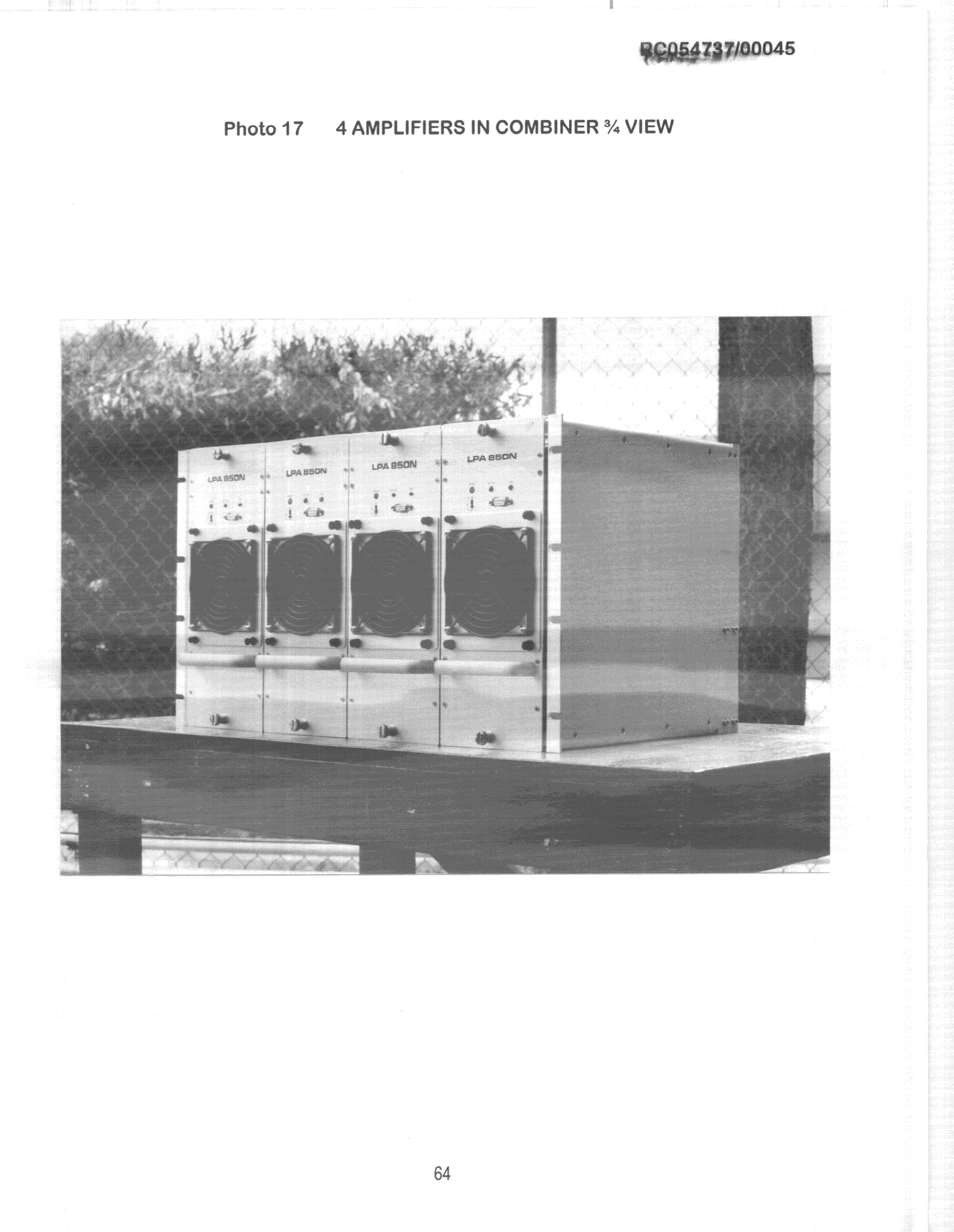
OQ3MS800-200
Mar 22, 2000AMP - Amplifier
Equipment Class
AMP - Amplifier