OQL-C-IPACiPAC Controller
PAC International Limited
Click to zoom
Application Details
- Equipment Class
- DCD - Part 15 Low Power Transmitter Below 1705 kHz
- Date of Grant
- Mar 21, 2010
- Application Purpose
- Original Equipment
- Date of Application
- Mar 21, 2010
- Equipment Note
- iPAC Controller
- Frequency Range
- 0.13190000 - 0.13470000
- Company
- PAC International Limited
- Country
- United Kingdom
Documents & Files
Document Text
Text extracted from the exhibit documents filed with the FCC. Open a document above to read the original.
Users Manual
FCC ID: OQL-C-IPAC This device complies with Part 15 of the FCC Rules. Operation is subject to the following two conditions: (1) this device may not cause harmful interference, and (2) this device must accept any interference received, including interference that may cause undesired operation. Note: This equipment has been tested and found to comply with the limits for a Class A digital device, pursuant to part 15 of the FCC Rules. These limits are designed to provide reasonable protection against harmful interference when the equipment is operated in a commercial environment. This equipment generates, uses, and can radiate radio frequency energy and, if not installed and used in accordance with the instruction manual, may cause harmful interference to radio communications. Operation of this equipment in a residential area is likely to cause harmful interference in which case the user will be required to correct the interference at his own expense. 3 iPAC Access Controller Quick Start Guide iPAC Zutrittgruppekontroller Installationsanleitung iPAC Contrôleur d’accès Guide d’installation iPAC Controlador de acceso Guía de instalación iPAC Styrenhet för access Installationsanvisningar iPAC Toegangscontrol Installatiehandleiding iPAC Styreenhet for adgang Installasjonsguide iPAC 䮼ࠊ఼ ᖿ䗳ਃࡼᣛफ 4 N1 +V EARTH 13 14 16 17 1920 15 18 5V 12/24V - + 2 2 2 4 3 0V +V - + 3 0V +V 12 10 9 1 SIG A SIG B 0V DC RTE I/P LED +V OVRD TAMP 0V N0 NGND N1 VIN 0V MSTAT LOCK 0V NC NO COM NC NO COM SIG A SIG B 0V DC RTE I/P LED +V NC NO COM NC NO COM 0V +V 21 7 110/ 240 Va c 5 6 8 11 0V D1 D0 SIG LED SCRN 5 English Introduction This document is intended for experienced engineers who are familiar with PAC products and health and safety considerations. The iPAC can be connected to slave PAC 512 controllers on the RS-485 network. Note It is recommended that all controllers on the system have the same firmware version number. Therefore, a firmware download to the controllers may be required. See the help file for details. Tamper and Override Terminal Because tamper and override are normally closed switches, use a short piece of cable to link the TAMP and 0V terminals and OVRD and 0V terminals before powering up. RS-485 If shielded cables are used, to avoid ground loops, the shield for each cable must be connected to ’SCRN’ at only one controller. The first and last controllers in the chain (and no others) must have the RS-485 termination jumper linked (set to IN). The red RS-485 LED indicates when the controller is transmitting data and the green RS-485 LED indicates when there is data on the network. Lock Suppression All locks must be fitted with a means of suppressing back EMF (‘spikes’) generated by most electric releases, especially magnetic locks. All readers and controllers supplied by PAC are supplied with a Metal Oxide Varistor (MOV). If large currents are used (i.e. >1A) use the large MOV supplied with the controller. If small currents are used (i.e. <1A) use the small MOV supplied with the reader. The MOV will prevent long term damage being done to the controller. Whenever possible this device should be fitted across the lock terminals. If for any reason, the lock terminals are inaccessible, the MOV may be fitted across the lock output. If a diode is already connected across the lock terminals, this must be removed, otherwise it will override the action of the MOV. Lock Relays The lock relays are protected by a 2A @ 30V circuit breaker in line with the RELAY COM connection. These will be automatically reset when overload has been removed; both lock outputs are independent. After Installation Press the yellow button to obtain help information. The USB pen must be compatible and FAT16 or FAT32 format (see TB224). 6 Key to Wiring Diagram on Page 4 1RS-485 Network (CAT5 twisted pair recommended) N1 N0 NGND SCRN (for shield) 2Reader +V LED/VCA SIGA/SIGB 0V (tamper / DC door contact) 0V (sounder) 0V Red Brown White Blue (normally closed) Yellow Black 3Fail-Safe Lock NC NO COM 4Request to Exit - normally open switch 0V(RTE) 0V Blue Black 5Battery Backup 612V/12-28V Power Supply Unit VIN 0V MSTAT Orange White Pink 7USB 8Ethernet 9USB PC Interface Kit 10Web Interface PC 7 11External Reader - not Easikey reader 0V D1 D0 SIG LED (+12V from +V on controller or separate supply, +5V not supported.) 12Case Tamper and Override Switch OVRD TAMP 0V 13RS-485 Termination Jumper 14RS-485 Status LEDs 15RS-232 Status LEDs 16DOOR 1 LEDs 17DOOR 2 LEDs 18Reader Data SIG A/SIG B pull up: Both door channels pulled up to 5V or 12/24V or rely on reader to pull up line. 19One-Touch™ Button 20System Status LED 21Power Access LOCK 0V Red Black Green/Yellow Materials All materials used conform to the ROHS directive. The unit contains a fixed lithium battery and must be disposed off in accordance with local regulations. One-Touch™ Test Mode To speed up installation and testing, One-Touch™ testing is provided which allows the controller functionality to be tested at the controller or reader. 8 TestAction Observation ControllerReader Normal Operation The green system status LED flashes at normal rate. The normal operation of the reader. Door status LEDs off. One-Touch™ View Mode Hold down the One-Touch™ button for less than 2 seconds. Present keys and press RTE switches and observe LEDs. Automatically exits after 2 minutes. The green system status LED flashes at normal rate. Green on - valid key has been presented to reader. Green flash - invalid key has been presented to reader. Red on - door open. Yellow on - RTE switch has been pressed. One-Touch™ Active Mode Hold down the One-Touch™ button for 2 to 4 seconds. The green system status LED flashes faster than normal. The normal operation of the reader LED changes, e.g. if default is red, it turns green. 9 TestAction Observation ControllerReader Reader and Request to Exit Test Present a key to each reader - the lock will activate. The door green LED flashes once for SIGA, twice for SIGB. The read…
Text truncated - open the document above for the full version.
Attestation Statements
SSS - Europe Stanley Security Solutions - Europe Ltd. Registered Office: Stanley House, Bramble Road, Swindon, Wilts. SN2 8ER United Kingdom. Tel: +44 1793 692401. Fax: +44 1793615848 TRL 51F047 iss02B LETTER OF AGENCY 11/3/2010 TRaC Global 100 Frobisher Business Park Leigh Sinton Road Malvern Worcestershire WR14 1BX UK To Whom It May Concern: We certify that we are not subject to denial of federal benefits, that includes FCC benefits, pursuant to Section 5301 of the Anti-Drug Abuse ACT of 1988, U.S.C. 862. Further, no party, as defined in 47 CFR 1.2002(b), to the application, is subject to denial of federal benefits, that includes FCC benefits. Thank you for your attention to this matter. Thank you for your attention to these matters. Yours faithfully Stanley Security Solutions – Europe Ltd. Paul Lucas
Cover Letter(s)
SSS - Europe Stanley Security Solutions - Europe Ltd. Registered Office: Stanley House, Bramble Road, Swindon, Wilts. SN2 8ER United Kingdom. Tel: +44 1793 692401. Fax: +44 1793615848 TRL 51F050 iss02B REQUEST FOR CONFIDENTIALITY I N ACCORDANCE WITH FCC RULE 0.459 11/3/2010 TRaC Global 100 Frobisher Business Park Leigh Sinton Road Malvern Worcestershire WR14 1BX UK RE: Certification Application FCC ID: OQL-C-IPAC To Whom It May Concern: Please be advised that the following information is to be held confidential on behalf of Stanley Security Solutions Europe Ltd. • Operational Description • Schematic Diagram • Block Diagram • Parts List The application contains technical information which Stanley Security Solutions Europe Ltd. deems to be trade secrets and propriety. If made public, the information might be used to the disadvantage of the applicant in the market place. Thank you for your attention to this matter. Yours faithfully Stanley Security Solutions – Europe Ltd. Paul Lucas
External Photos
Overview
ID Label/Location Info
SSS - Europe Stanley Security Solutions - Europe Ltd. Registered Office: Stanley House, Bramble Road, Swindon, Wilts. SN2 8ER United Kingdom. Tel: +44 1793 692401. Fax: +44 1793615848 Labelling Information Label 1: 2933 25.5mm x 60mm Fitted to the left side of the iPAC controller Label 2: 2934 25.5mm x 60mm Fitted to the right side of the iPAC controller Material Information: 1. CLEAR POLYCARBONATE, 125 MICRONS THK 2. SUB SURFACE PRINTED 3. COLOURS: BLACK - GRAPHICS/TEXT WHITE - BACKGROUND 4. SELF ADHESIVE ON REVERSE 5. MATERIALS & PROCESS TO BE UL APPROVED
ID Label/Location Info
FCC Label Location
Test Report
Total number of pages: 40 TRaC Wireless Test Report:0F3071WUS1 Applicant:Stanley Security Solutions Ltd Apparatus:iPAC Controller Specification(s):CFR47 Part 15 .209 July10 th 2008 :CFR47 Part 15.109(b) July 10 th 2008 Purpose of Test: Certification FCCID: OQL-C-IPAC Authorised by: : Radio Product Manager Issue Date:18 th March 2010 Authorised Copy Number: PDF Radio Test Report: 0F3071WUS1 2 Contents Section 1:Introduction3 1.1General3 1.2Tests Requested By4 1.3Manufacturer4 1.4Apparatus Assessed5 1.5Test Result Summary6 1.6Notes Relating To The Assessment7 1.7Deviations from Test Standards7 Section 2:Measurement Uncertainty8 2.1Application of Measurement Uncertainty8 2.2Measurement Uncertainty Values9 Section 3:Modifications11 3.1Modifications Performed During Assessment11 Appendix A:Formal Emission Test Results12 A1Transmitter Intentional Emission Radiated13 A2Radiated Electric Field Emissions14 A3Power Line Conducted Emissions16 A5Unintentional Radiated Emissions18 Appendix B:Supporting Graphical Data20 Appendix C: Additional Test and Sample Details27 Appendix D:Additional Information33 Appendix E:Photographs and Figures34 Radio Test Report: 0F3071WUS1 3 Section 1:Introduction 1.1General This report contains an assessment of an apparatus against Electromagnetic Compatibility Standards based upon tests carried out on samples submitted to the Laboratory. Test performed by: TRaC Telecoms & Radio Moss View Nipe Lane Up Holland West Lancashire, WN89PY United Kingdom Telephone:+44 (0) 1695 556666 Fax:+44 (0) 1695 577077 Email:[email protected] Web site:http://www.tracglobal.com Tests performed by:S Hodgkinson Report author:S Hodgkinson This report must not be reproduced except in full without prior written permission from TRaC Telecoms & Radio. Radio Test Report: 0F3071WUS1 4 1.2Tests Requested By This testing in this report was requested by : Stanley Security Solutions Ltd 1 Park Gate Close Bredbury Stockport SK6 2SZ +44 (0) 0161 4063418 1.3Manufacturer Stanley Security Solutions Ltd 1 Park Gate Close Bredbury Stockport SK6 2SZ +44 (0) 0161 4063418 Radio Test Report: 0F3071WUS1 5 1.4Apparatus Assessed. iPAC Controller The apparatus was assessed between10 th – 16 th March 2010 Product Description The iPAC is a two door access controller. It has the necessary interface to be able to connect external RFID readers, electronic locks and door sensors to the door channels. These external peripherals are not supplied with the equipment. The iPAC is a standalone door controller and does not need a controlling PC connection to operate. The iPAC is fitted with an on board user interface and an integrated RFID administration reader which allows the operator to directly administer the controller, it can also be administered via a web browser by connecting to an Ethernet network. The operator adds unique RFID tokens to the iPAC and administers the access rights of the token and hence user access. The user presents a RFID token to the external readers connected to the door channels, if the user is allowed access the controller actuates the lock. The controller can control a LED on the external reader which is used to indicate the state of the lock i.e. red for locked, green for access and red/green for access denied. The iPAC can also connect to a door sensor switch to indicate events such as door left open or door forced. All user data is held in battery backed RAM on the controller. Radio Test Report: 0F3071WUS1 6 1.5Test Result Summary Full details of test results are contained within Appendix A. The following table summarises the results of the assessment. The statements relating to compliance with the standards below apply ONLY as qualified in the notes and deviations stated in sections 1.6 to 1.7 of this test report. Full details of test results are contained within Appendix A. The following table summarises the results of the assessment. Test TypeRegulation Measurement standard Result Spurious Emissions Radiated <1000MHz Title 47 of the CFR: Part 15 Subpart (c) 15.209 ANSI C63.10Pass Spurious Emissions Radiated >1000MHz Title 47 of the CFR: Part 15 Subpart (c) ANSI C63.10N/A AC Power conducted emissions Title 47 of the CFR: Part 15 Subpart (c) 15.207 ANSI C63.10Pass Intentional Emission Frequency Title 47 of the CFR: Part 15 Subpart (c) ANSI C63.10N/A Intentional Emission Field Strength: Title 47 of the CFR: Part 15 Subpart (c) 15.209 ANSI C63.10Pass Intentional Emission Band Occupancy Title 47 of the CFR: Part 15 Subpart (c) 15.209 ANSI C63.10Pass Intentional Emission ERP (mW) Title 47 of the CFR: Part 15 Subpart (c) ANSI C63.10N/A Unintentional Radiated Spurious Emissions Title 47 of the CFR: Part15 Subpart (b) 15.109 ANSI C63.10Pass Antenna Arrangements Integral: Title 47 of the CFR: Part 15 Subpart (c) 15.203 -Pass Antenna Arrangements External Connector Title 47 of the CFR: Part 15 Subpart (c) 15.204 -N/A Restricted Bands Title 47 of the CFR: Part 15 Subpart (c) 15.205 -Pass Maximum Frequency of Search Title 47 of the CFR: Part 15 Subpart (c) 15.33 -Pass Extrapolation Factor Title 47 of the CFR: Part 15 Subpart (c) 15.31(f) -√ Abbreviations used in the above table: CFR: Code of Federal RegulationsANSI: American National Standards Institution REFE: Radiated Electric Field EmissionsPLCE: Power Line Conducted Emissions Radio Test Report: 0F3071WUS1 7 1.6Notes Relating To The Assessment With regard to this assessment, the following points should be noted: The results contained in this report relate only to the items tested and were obtained in the period between the date of initial receipt of samples and the date of issue of the report. The apparatuswas set up and exercised using the configurations, modes of operation and arrangements defined in this report only. Particular operating modes, apparatus monitoring methods and performance criteria required by the standards tested to have been performed except where identified in Section 1.7 of this test report (Deviations from Test Standards). For …
Text truncated - open the document above for the full version.
Test Setup Photos
Test Setup Test Setup
Contact Information
Applicant
Shaun C Byrne(Controller Team Leader)
Test Firm
Element Materials Technology Warwick LtdMax Leach
Technical Specifications
| # | Rule Parts | Frequency Range | Power Output |
|---|---|---|---|
| 1 | 15C | 0.1319 MHz - 0.1347 MHz | - |
Other Applications from PAC International Limited
OQLGS3LFP
Aug 01, 2013Panel LF Reader GS3 OneProx
Equipment Class
DCD - Part 15 Low Power Transmitter Below 1705 kHz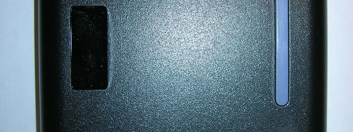
OQLGS3LFS
Aug 01, 2013Standard LF Reader GS3 OneProx
Equipment Class
DCD - Part 15 Low Power Transmitter Below 1705 kHz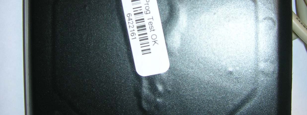
OQLGS3LFV
Aug 01, 2013Vandal LF Reader GS3 OneProx
Equipment Class
DCD - Part 15 Low Power Transmitter Below 1705 kHz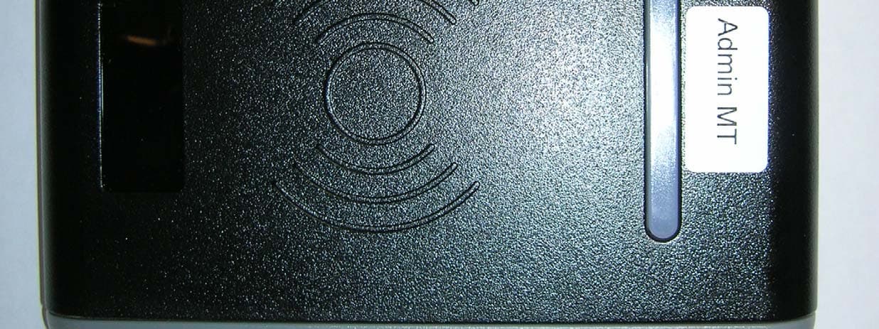
OQLGS3MTA
Jul 31, 2013Admin MT Reader GS3 OneProx
Equipment Class
DXX - Part 15 Low Power Communication Device Transmitter
OQLGS3PIN
Jul 30, 2013PIN MT Reader GS3 OneProx
Equipment Class
DXX - Part 15 Low Power Communication Device Transmitter