OQL-EK-CONAccess controller with low range proximity reader
PAC International Limited
Click to zoom
Application Details
- Equipment Class
- DCD - Part 15 Low Power Transmitter Below 1705 kHz
- Date of Grant
- Jan 08, 2003
- Application Purpose
- Original Equipment
- Date of Application
- Jan 08, 2003
- Equipment Note
- Access controller with low range proximity reader
- Frequency Range
- 0.15350000 - 0.15350000
- Company
- PAC International Limited
- Country
- United Kingdom
Documents & Files
Document Text
Text extracted from the exhibit documents filed with the FCC. Open a document above to read the original.
Users Manual
PAC INTERNATIONAL LTD, 1 Park Gate Close, Bredbury, Stockport, SK6 2SZ, England Tel: +44 (0) 161 406 3400. Fax: +44 (0) 161 430 8658 www.pac.co.uk Easikey Installation and User Guide 17086 Ver 3.3 DRAFT C January 2003 17086 Ver 3.3 DRAFT C iiEasikey Version 3.3January 2003 Changes are periodically made to the product, these changes will be incorporated into new editions of this manual. PAC INTERNATIONAL LTD shall not be liable for errors contained herein or for any consequential damages connected with the use of this material. Copyright and Protective Notices 1. The copyright of this document and the associated drawings is the property of PAC INTERNATIONAL LTD, and is issued on condition that it is not copied, reprinted or reproduced, nor its contents disclosed, either wholly or in part, without the consent in writing of, or in accordance with the conditions of a contract with PAC INTERNATIONAL LTD. 2. The publication of information in this document does not imply freedom from patent or other protective rights of PAC INTERNATIONAL LTD, or others. 3. Performance figures and data quoted in this document are typical, and must be specifically confirmed by PAC INTERNATIONAL LTD before they become applicable to any tender, order or contract. Training and Technical Support Training courses covering the installation and use of all PAC products are regularly held at PAC INTERNATIONAL LTD, Stockport. For further information on course availability, or to discuss your specific requirements, contact the Training Manager at the address below. It is strongly recommended that any persons installing or commissioning PAC products attend a suitable training course beforehand. Technical Support for all PAC products is available during normal office hours: 8:00am to 6:00pm Monday to Friday, excluding public holidays. Tel: 0161 406 3400International +44 161 406 3400 Fax: 0161 430 8658International +44 161 430 8658 This service is provided primarily for the use of trained engineers. End users of PAC products should first of all contact their installation or maintenance company before contacting PAC. PAC INTERNATIONAL LTD 1 Park Gate Close Bredbury Stockport SK6 2SZ England 17086 Ver 3.3 DRAFT C iiiEasikey IMPORTANT: When installing the PAC equipment the following should be noted: HEALTH AND SAFETY Installation must wired in accordance with National Wiring Regulations (BS7671, IEE National Wiring Regulations in the UK). Failure to do so can result in injury or death by electric shock. It must also comply with any local Fire, Health and Safety regulations. A secured door that may be part of an escape route from an area must be fitted with: •A fail-safe lock (A) so that the door will be released if the power fails. Ideally a magnetic lock should be used as these are less likely to jam or seize. •A normally-closed break-glass or manual pull (B) in the lock supply wiring so that in an emergency the fail-safe lock can be immediately depowered. B A The controller must be earthed. Isolate the controller supply before working on the controller. CABLING The cabling used in the PAC Access Control Systems (six wire bus, reader cables, etc.) are not prone to electrical interference. However, you should avoid routing cable close to heavy load switching cables and equipment. If this is unavoidable, cross the cable at right angles every 3.3-6.6ft/1-2m to reduce the interference. RFID Devices As similar RFID technology is now widely used in a number of other industries, for example automotive immobilisers, it is possible that interaction between your access control ID and other devices may cause one or the other to function incorrectly. Should you suspect that you have experienced such a problem the solution is to separate your access control ID from other RFID devices. FCC Notice This device complies with part 15 of the FCC rules. Operation is subject to the following two conditions (1) this device may not cause harmful interference, and (2) this device must accept any interference received, including interference that may cause undesired operation. FCC ID OQL-EK-CON Changes or modifications not expressly approved by the party responsible for compliance could void the user's authority to operate the equipment. Note This equipment has been tested and found to comply with the limits for a Class B digital device, pursuant to part 15 of the FCC Rules. These limits are designed to provide reasonable protection against harmful interference in a residential installation. This equipment generates, uses and can radiate radio frequency energy and, if not installed and used in accordance with the instructions, may cause harmful interference to radio communications. However, there is no guarantee that interference will not occur in a particular installation. If this equipment does cause harmful interference to radio or television reception, which can be determined by turning the equipment off and on, the user is encouraged to try to correct the interference by one or more of the following measures: • Reorient or relocate the receiving antenna. • Increase the separation between the equipment and receiver. • Connect the equipment into an outlet on a circuit different from that to which the receiver is connected. • Consult the dealer or an experienced radio/TV technician for help. 17086 Ver 3.3 DRAFT C ivEasikey This page is intentionally left blank. 17086 Ver 3.3 DRAFT C vEasikey Table of Contents 1.1 Facilities ............................................................................................................................... 1 1.2 Features............................................................................................................................... 3 1.3 About this Guide .................................................................................................................. 3 2.1 Components ................................................................................................................…
Text truncated - open the document above for the full version.
ID Label/Location Info
IDENTIFICATION LABELS The labels below are fitted as shown in the photo. The unit is marketed under the model numbers 20373 and 20373/2. The labels are made of polycarbonate. The adhesive is 3M468 (or equivalent). The label quality and adhesion satisfies UL requirements. INTERNATIONAL LTD FIX BARCODE HERE Made in UK 610/5 X Date Code: Rating: Model No.: FCC ID: OQL-EK-CON cause undesired operation. This device complies with Part 15 of the FCC Rules. Operation is subject to the following two conditions: (1) this device may not cause harmful interference, and (2) this device must accept any interference received, including interference that may 1559/1
Internal Photos
INTERNAL PHOTOS
Test Report
Page 1 of 15 Member of the SGS Group (Société Générale de Surveillance) Registered in England No. 1193985. Registered Office: Inward Way, Rossmore Business Park, Ellesmere Port, Cheshire, CH65 3EN. SGS United Kingdom Ltd. International Electrical Approvals abc South Industrial Estate Bowburn Co. Durham DH6 5AD United Kingdom Tel: +44 (0) 191 377 2000 Fax: +44 (0) 191 377 2020 email: [email protected] Electromagnetic Compatibility Test of: RF Card Entry System Model Number: Refer to page 5 Applicant: PAC International Ltd Test Type: Compliance Test Specification: Test Result: FCC CFR47, parts 15.107, 15.109, 15.207 and 15.209 Complied SGS Serial Number: DUR 24095.1/EMC/LS/02 Date of Receipt: 10 th June 2002 Date of Test(s): 10 th June 2002 – 20 th June 2002 Date of Issue: 10 th January 2003 Issue Number: 4 This report refers only to the sample submitted for test. This report shall not be reproduced except in full without the written approval of the testing laboratory. Test EngineerAuthorised Signatory L.SteelA. Reynard Technical Manager abc TEST REPORT Page 2 of 15 Issue Date:10 th January 2003 SGS Serial Number:DUR24095.1/EMC/LS/02 Issue Number: 4 CONTENTSPage Number 1. Client Information ........................................................................................................................... 3 2. Details Of Test Laboratory............................................................................................................. 3 3. Equipment Under Test (EUT) ........................................................................................................ 4 3.1 Identification Of EUT...................................................................................................................................................... 4 4. Test Specification, Methods and Procedures ............................................................................. 5 4.1 Test Specification(s) ...................................................................................................................................................... 5 4.2 Purpose Of Test............................................................................................................................................................. 5 4.3 Methods and Procedures............................................................................................................................................... 5 EUT System Diagram............................................................................................................................ 6 5. Deviations or Exclusions from the Test Specifications ............................................................. 7 6. Operation of the EUT During Testing / Configuration and Peripherals .................................... 7 6.1 Operation of EUT during testing. ................................................................................................................................... 7 6.2 Configuration and Peripherals ........................................................................................................................................ 7 7. Test Results .................................................................................................................................... 8 7.1 General Comments........................................................................................................................................................ 8 7.2 Modifications Made to the EUT...................................................................................................................................... 8 7.3 Summary of Test Results .............................................................................................................................................. 8 7.4Conducted Emissions Test Results – 15.107/15.207 ............................................................. 9 7.5Radiated Emissions Test Results – 15.109.......................................................................... 12 7.6Radiated Emissions Test Results – 15.209.......................................................................... 14 abc TEST REPORT Page 3 of 15 Issue Date:10 th January 2003 SGS Serial Number:DUR24095.1/EMC/LS/02 Issue Number: 4 1. Client Information Company Name: PAC International Ltd Address: 1 Park Gate Close, Bredbury, Stockport, SK6 2SZ. Contact Person: Shaun Byrne Telephone: 0161 406 3400 Facsimile: 0161 430 8658 2. Details Of Test Laboratory Company Name: SGS International Electrical Approvals UKAS Accreditation Number: 1116 Address: South Industrial Estate, Bowburn, Co. Durham, DH6 5AD. Contact Persons: Mr Alan Reynard Telephone: 0191 377 2000 Facsimile: 0191 377 2020 abc TEST REPORT Page 4 of 15 Issue Date:10 th January 2003 SGS Serial Number:DUR24095.1/EMC/LS/02 Issue Number: 4 3. Equipment Under Test (EUT) 3.1Identification Of EUT Model Number: Refer to page 5. Unique Identifier: Refer to page 5 Description of EUT: RF Card Entry System Internal Clock Frequencies: Refer to page 5. Supply Voltage: (To Controller) 12 or 15v dc via ac/dc adapter (see page 5) NOTE: All other parts of the system obtain their power via the controller. Classification: Refer to page 5. Accessories Supplied: Refer to page 5. abc TEST REPORT Page 5 of 15 Issue Date:10 th January 2003 SGS Serial Number:DUR24095.1/EMC/LS/02 Issue Number: 4 4. Test Specification, Methods and Procedures 4.1Test Specification(s) Specification(s)Title FCC CFR 47 : October 1999 Parts 15.107/15.207, 15.109 and 15.209 Code Of Federal Regulations 4.2Purpose Of Test 1) To test the whole system to clauses 15.107/15.207 and 15.109 2) To test the 20373 front panel card reader only, to the requirements of 15.209 (Upto 30 MHz only). 4.3Methods and Procedures The standard listed above refers to the following tests: - CFR 47 ClauseTest 15.107/15.207Conducted Emissions (Intentional and Unintentional Radiators) 15.109 (30-1000 MHz) Radiated Emis…
Text truncated - open the document above for the full version.
Test Setup Photos
abc TEST REPORT Page 11 of 15 Issue Date:29th November 2002 SGS Serial Number:DUR24095.1/EMC/LS/02 Issue Number: 1 Conducted Emissions Test Configuration Conducted Emissions Environmental Conditions Power Supply (to controller) 120V, 60Hz Temperature 19.5°C Relative Humidity 43% Barometric Pressure 994mb Conducted Emissions Measurement Uncertainties Frequency ± 200kHz Amplitude ± 3.0dB The uncertainties stated are calculated in accordance with the requirements of UKAS with a confidence level of 95%. Test Equipment Used Equipment TypeModel Number LISN (50Ω) Thurlby Thandar TTi 1600 Chase ReceiverLHR7000 SoftwareVersion 6.00b SGS Screened Room- Spectrum AnalyserHP8563E Check Equip.PLC 1C abc TEST REPORT Page 13 of 15 Issue Date:29th November 2002 SGS Serial Number:DUR24095.1/EMC/LS/02 Issue Number: 1 Radiated Emissions Test Configuration Radiated Emissions Environmental Conditions Power Supply (to controller) 120V AC, 60 Hz Temperature 14.5°C Relative Humidity 46% Barometric Pressure 992mb Radiated Emissions Measurement Uncertainties Frequency ± 200kHz Amplitude ± 4.6dB The uncertainties stated are calculated in accordance with the requirements of UKAS with a confidence level of 95%. Test Equipment Used Equipment TypeModel Number Receiver SystemHP 8573B Biconical AntennaEMCO 3110 Log Periodic AntennaEMCO 3146 Pre-amplifierZHL 1042J Check Equip.York CNE III SoftwareOpen Site HP85879 abc TEST REPORT Page 15 of 15 Issue Date:29 th November 02 SGS Serial Number:DUR24095.1/EMC/LS/02 Issue Number: 1 Radiated Emissions Test Configuration Radiated Emissions Environmental Conditions Power Supply (to controller) 120V AC, 60 Hz Temperature 13°C Relative Humidity 59% Barometric Pressure 976mb Radiated Emissions Measurement Uncertainties Frequency ± 200kHz Amplitude ± 4.6dB The uncertainties stated are calculated in accordance with the requirements of UKAS with a confidence level of 95%. Test Equipment Used Equipment TypeModel Number Loop AntennaEMCO 6502 Spectrum AnalyserHP8563E
Contact Information
Applicant
Shaun C Byrne(Controller Team Leader)
Technical Contact
PAC INTERNATIONAL LTDRobert W Harvey
[email protected]++44 161 4063400
1 PARK GATE CLOSE, BREDBURY · STOCKPORT, CHESHIRE · United Kingdom
Non-Technical Contact
PAC INTERNATIONAL LTDMike Cook
[email protected]++44 161 4063400
Test Firm
SGS United Kingdom Ltd.Stephen Thompson
Technical Specifications
| # | Rule Parts | Frequency Range | Power Output |
|---|---|---|---|
| 1 | 15C | 0.1535 MHz - 0.1535 MHz | - |
Other Applications from PAC International Limited
OQLGS3LFP
Aug 01, 2013Panel LF Reader GS3 OneProx
Equipment Class
DCD - Part 15 Low Power Transmitter Below 1705 kHz
OQLGS3LFS
Aug 01, 2013Standard LF Reader GS3 OneProx
Equipment Class
DCD - Part 15 Low Power Transmitter Below 1705 kHz
OQLGS3LFV
Aug 01, 2013Vandal LF Reader GS3 OneProx
Equipment Class
DCD - Part 15 Low Power Transmitter Below 1705 kHz
OQLGS3MTA
Jul 31, 2013Admin MT Reader GS3 OneProx
Equipment Class
DXX - Part 15 Low Power Communication Device Transmitter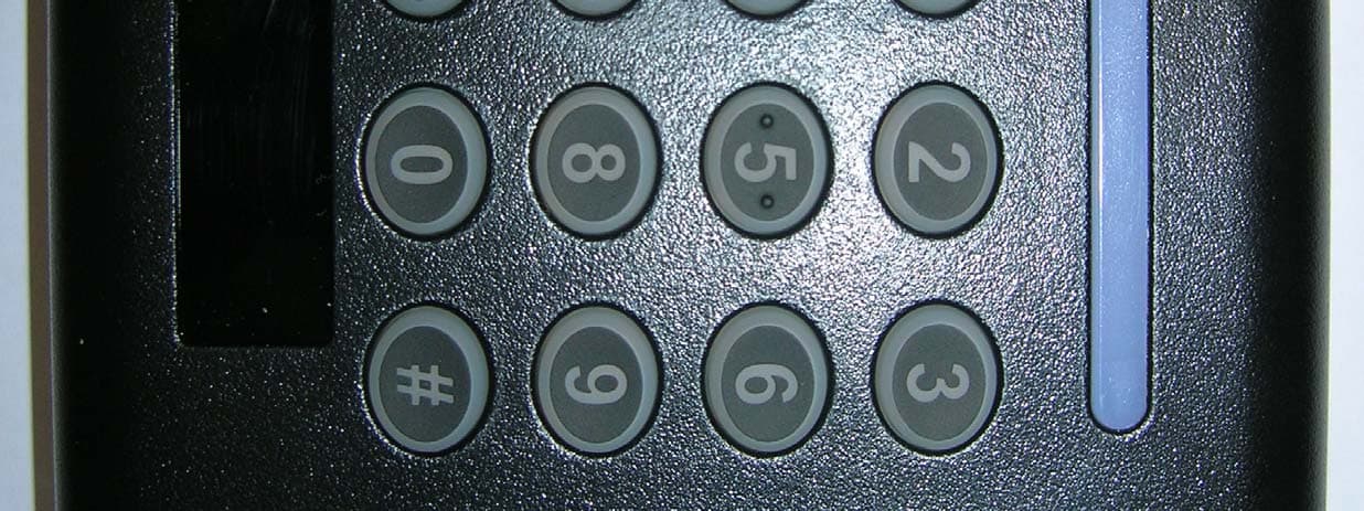
OQLGS3PIN
Jul 30, 2013PIN MT Reader GS3 OneProx
Equipment Class
DXX - Part 15 Low Power Communication Device Transmitter