OQL-P-PINLow range proximity reader
PAC International Limited
Click to zoom
Application Details
- Equipment Class
- DCD - Part 15 Low Power Transmitter Below 1705 kHz
- Date of Grant
- Jan 09, 2003
- Application Purpose
- Original Equipment
- Date of Application
- Jan 09, 2003
- Equipment Note
- Low range proximity reader
- Frequency Range
- 0.15350000 - 0.15350000
- Company
- PAC International Limited
- Country
- United Kingdom
Documents & Files
Document Text
Text extracted from the exhibit documents filed with the FCC. Open a document above to read the original.
Users Manual
Data Sheet January 200315826 Ver 1.8 DRAFT C PAC Portico, 1 Lower Ragsdale Drive, Building 3, Suite 800, Monterey, California 93940 USA www.PACPortico.com This document is correct at the time of going to press. However, as part of our ongoing product enhancement program we reserve the right to make changes to the product and/or literature at any time without prior notice. PAC Portico PIN Reader Installation Guide Surface and Flush Mounted Introduction This data sheet describes the PAC Portico Surface Mounted PIN Reader and PAC Portico Flush PIN Reader (pictured below). Surface Mounted Flush Mounted LED KEYPAD READER Application The PIN reader is of particular use in high security applications, having the extra security of a Personal Identification Number (PIN) number as well as a PAC Portico key (or card). The use of low cost, unscreened, signal alarm cable is recommended to connect the reader to the door controller. General Description and Operation To gain access through a door the user must first present a valid PAC Portico key to the built-in reader. Once the key has been read, the Light Emitting Diode (LED) will momentarily change from red to green. The user must then enter their 4-digit PIN number via the keypad. The LED will blink green and the built-in sounder will beep as each key is pressed. Once the PIN has been entered, if the PIN is correct, the LED will become green to indicate the door is unlocked. If the PIN is incorrectly entered, four further attempts may be made to gain access (by re- presenting the key and re-entering the PIN) before the individual key becomes locked out. The lock-out is cleared when a different key is used. Once a key becomes locked out, it remains locked out for 2 hours; this lock-out period will expire when the key has not been presented to the reader during that 2 hour period. Using a key when it has been locked out, will cause the lock-out period to be increased by 2 hours. 15826 Ver 1.8 DRAFT CPAC Portico PIN Reader Installation Guide Page 2© 2003 Blick USA, Inc Example If a locked out key is presented to a reader 10 minutes before its 2 hour period is completed, the lock-out period will be extended to 2 hours 10 minutes. A duress facility is available which may be activated by the user adding 1 to the last digit of their PIN (i.e. PIN numbers of 1234 has a duress code of 1235). The duress code will open the door and will also set off a predefined signal, such as an alarm (this feature will need to be configured separately with a standalone system or through PAC Portico for Windows). The use of a PIN number is optional and may be controlled by a time profile (i.e. at certain times a key only may be required to gain access, at other times a key and PIN must be used). Note Each PIN number is derived from the key and cannot be changed. The reader is not prone to electrical interference from normal electrical equipment, however care should be taken to avoid mounting the reader and cables in close proximity to heavy load switching cables and equipment. The performance of the readers is unaffected by the material of the mounting surface but make sure the mounting surface is as even as possible to provide maximum protection to the reader. Try to mount the reader at a height which it is easy to operate at; a recommended height for an able bodied person is 5.0-5.6ft/1.5-1.7m. Also the reader should be in a well lit place. Reader Installation It is not recommended to mount the reader externally but if it is installed externally, all exposed terminals on the reader and the connector strip must be protected by a proprietary sealant, e.g. silicone rubber compound. Use the reader as a template in order to accurately mark the fixing points onto the mounting surface. Flush Mounted This reader is designed to be flush mounted onto a standard 2 gang (1.4in/35mm) back box using the two M3.5 (1in/25mm x 0.14in/3.5mm) screws provided. The connecting cable can be taken directly from the terminals through the knock-outs in the back box via a suitable grommet and through a suitably prepared hole in the mounting surface. The dimensions of the flush mounted reader are 4.0in/100mm x 5.8in/144mm. PAC Portico PIN Reader Installation Guide15826 Ver 1.8 DRAFT C © 2003 Blick USA, IncPage 3 Surface Mounted The reader is designed to be surface mounted onto a flat surface using the two holes provided, therefore not requiring the installation of a back box. The readers performance is unaffected by the material of the mounting surface. Ensure the surface is as even as possible to provide maximum protection against the reader being levered from the wall. The connecting cable can be taken via the hole provided on the lower section of the reader housing and then surface mounted, preferably under the protection of a suitable conduit. Alternatively, the cable could be taken directly from the terminals through a suitably prepared hole in the mounting surface so as to be completely hidden from sight. The holes are designed to accept size No.8 countersunk screws, preferably anti-tamper type, with a recommended minimum length of 2in/50mm. This recommended length of course depends on the surface type and construction. The dimensions of the surface mounted reader are 8in/200mm x 4in/100mm x 1.3in/30mm. Connections Reader Connections The connections for both readers are: ColorSignalNotes Black0VNegative supply WhiteSIGReader signal BrownVCAValid code accept LED Red+12VPositive supply 15826 Ver 1.8 DRAFT CPAC Portico PIN Reader Installation Guide Page 4© 2003 Blick USA, Inc Cable Lengths The cross-sectional area determines the cable length: Cable GaugeEasikeyPAC 2100 Series PAC 2200 Series PAC 202 24AWG/0.22mm 2 240ft/80m325ft/200m66ft/20m 20AWG/0.5mm 2 550ft/180m1500ft/500m 18AWG/1.0mm 2 3000ft/1000m2250ft/700m Specification • Keypad: 10-digit rigid membrane keypad with visual target area for key presentation. • LED Indicator: Red LED flashing momentarily to green showing electronic key accepta…
Text truncated - open the document above for the full version.
Cover Letter(s)
Covering letter for FCC Form 731 Attachments 0.459 Request that submitted material be withheld from Public Inspection FCC ID OQL-P-PIN It is requested that the following exhibits be withheld from Public Inspection: • Operational Description • Schematic Diagram • Block Diagram • Internal Photos This information is considered to be PAC International proprietary and confidential. The unit is supplied fully encapsulated in hard potting - the design features are not evident from inspection hence reverse engineering is extremely problematic. This unit is believed to have a commercial advantage over our competition – revealing details of the design to our competitors would put us at a disadvantage. We therefore request that the above-listed items are withheld from public inspection. Shaun Byrne Principal Engineer PAC International Ltd
External Photos
EXTERNAL PHOTOS
ID Label/Location Info
IDENTIFICATION LABELS The labels below are fitted as shown in the photos. The labels are made of polycarbonate. The adhesive is 3M468 (or equivalent). The label quality and adhesion satisfies UL requirements. The flush mount unit is marketed under the model numbers 2001-P, K2001-P, 25362 and 20362 FLUSH MOUNT LABEL POSITIONS Made in UK VOLTAGE: 11.5 - 18.0V CURRENT: 100mA MAX FCC ID: OQL-P-PIN FIX BARCODE HERE Model No. 2001-P V + V C A S I G V - 1645/1 X D A T E C O D E INTERNATIONAL LTD The surface mount unit is marketed under the model numbers 2001-SP and 25361 SURFACE MOUNT LABEL POSITIONS Made in UK VOLTAGE: 11.5 - 18.0V CURRENT: 100mA MAX FCC ID: OQL-P-PIN FIX BARCODE HERE Model No. 2001-SP V + V C A S I G V - 1630/1 X D A T E C O D E INTERNATIONAL LTD
Test Report
Page 1 of 9 Member of the SGS Group (Société Générale de Surveillance) Registered in England No. 1193985. Registered Office: Inward Way, Rossmore Business Park, Ellesmere Port, Cheshire, CH65 3EN. SGS United Kingdom Ltd. International Electrical Approvals abc South Industrial Estate Bowburn Co. Durham DH6 5AD United Kingdom Tel: +44 (0) 191 377 2000 Fax: +44 (0) 191 377 2020 email: [email protected] Electromagnetic Compatibility Test of: RF Card Entry Reader Model Number: 25361 Applicant: PAC International Ltd Test Type: Compliance Test Specification: Test Result: FCC CFR47, part 15.209 (up-to 30 MHz) only. Complied SGS Serial Number: DUR 24094.5/EMC/LS/02 Date of Receipt: 30 th May 2002 Date of Test(s): 30 th May 2002 Date of Issue: 10 th January 2003 Issue Number: 3 This report refers only to the sample submitted for test. This report shall not be reproduced except in full without the written approval of the testing laboratory. Test EngineerAuthorised Signatory L.SteelA. Reynard Technical Manager abc TEST REPORT Page 2 of 9 Issue Date:10 th January 2003 SGS Serial Number:DUR24094.5/EMC/LS/02 Issue Number: 3 CONTENTSPage Number 1. Client Information ........................................................................................................................... 3 2. Details Of Test Laboratory............................................................................................................. 3 3. Equipment Under Test (EUT) ........................................................................................................ 4 3.1 Identification Of EUT...................................................................................................................................................... 4 4. Test Specification, Methods and Procedures ............................................................................. 5 4.1 Test Specification(s) ...................................................................................................................................................... 5 4.2 Purpose Of Test............................................................................................................................................................. 5 4.3 Methods and Procedures................................................................................................................................................ 5 5. Deviations or Exclusions from the Test Specifications ............................................................. 6 6. Operation of the EUT During Testing / Configuration and Peripherals .................................... 6 6.1 Operation of EUT during testing. ................................................................................................................................... 6 6.2 Configuration and Peripherals ........................................................................................................................................ 6 7. Test Results .................................................................................................................................... 7 7.1 General Comments........................................................................................................................................................ 7 7.2 Modifications Made to the EUT...................................................................................................................................... 7 7.3 Summary of Test Results ............................................................................................................................................... 7 7.4Radiated Emissions Test Results – 15.209............................................................................ 8 abc TEST REPORT Page 3 of 9 Issue Date:10 th January 2003 SGS Serial Number:DUR24094.5/EMC/LS/02 Issue Number: 3 1. Client Information Company Name: PAC International Ltd Address: 1 Park Gate Close, Bredbury, Stockport, SK6 2SZ. Contact Person: Shaun Byrne Telephone: 0161 406 3400 Facsimile: 0161 430 8658 2. Details Of Test Laboratory Company Name: SGS International Electrical Approvals UKAS Accreditation Number: 1116 Address: South Industrial Estate, Bowburn, Co. Durham, DH6 5AD. Contact Persons: Mr Alan Reynard Telephone: 0191 377 2000 Facsimile: 0191 377 2020 abc TEST REPORT Page 4 of 9 Issue Date:10 th January 2003 SGS Serial Number:DUR24094.5/EMC/LS/02 Issue Number: 3 3. Equipment Under Test (EUT) 3.1Identification Of EUT Model Number: 25361 Unique Identifier: S0078637 Description of EUT: RF Card Entry Reader Internal Clock Frequencies: (Maximum) 11.0592 MHz Supply Voltage: 18V DC from a Controller (Controller supply = 120 V AC, 60 Hz) Classification: Intentional and Unintentional Radiator Accessories Supplied: 2100 Controller abc TEST REPORT Page 5 of 9 Issue Date:10 th January 2003 SGS Serial Number:DUR24094.5/EMC/LS/02 Issue Number: 3 4. Test Specification, Methods and Procedures 4.1Test Specification(s) Specification(s)Title FCC CFR 47 : October 1999 Part 15.209 only Code Of Federal Regulations 4.2Purpose Of Test To perform the radiated emissions test to the above specification in the frequency range 9 kHz to 30 MHz only, as requested by the client. 4.3 Methods and Procedures The standard listed above refers to the following tests: - CFR 47 ClauseTest 15.209Radiated Emissions abc TEST REPORT Page 6 of 9 Issue Date:10 th January 2003 SGS Serial Number:DUR24094.5/EMC/LS/02 Issue Number: 3 5. Deviations or Exclusions from the Test Specifications There were no deviations from the test specifications. 6.Operation of the EUT During Testing / Configuration and Peripherals 6.1Operation of EUT during testing. Refer to individual test results sections for details of EUT operation during testing. 6.2Configuration and Peripherals The EUT was connected to a controller, (Manufacturer: PAC International, Model No: 25566, Serial No: Not supplied) in order to provide power to the EUT. The controll…
Text truncated - open the document above for the full version.
Test Report
Page 1 of 9 Member of the SGS Group (Société Générale de Surveillance) Registered in England No. 1193985. Registered Office: Inward Way, Rossmore Business Park, Ellesmere Port, Cheshire, CH65 3EN. SGS United Kingdom Ltd. International Electrical Approvals abc South Industrial Estate Bowburn Co. Durham DH6 5AD United Kingdom Tel: +44 (0) 191 377 2000 Fax: +44 (0) 191 377 2020 email: [email protected] Electromagnetic Compatibility Test of: RF Card Entry Reader Model Number: 25362 Applicant: PAC International Ltd Test Type: Compliance Test Specification: Test Result: FCC CFR47, part 15.209 (up-to 30 MHz) only. Complied SGS Serial Number: DUR 24094.4/EMC/LS/02 Date of Receipt: 30 th May 2002 Date of Test(s): 30 th May 2002 Date of Issue: 10 th January 2003 Issue Number: 3 This report refers only to the sample submitted for test. This report shall not be reproduced except in full without the written approval of the testing laboratory. Test EngineerAuthorised Signatory L.SteelA. Reynard Technical Manager abc TEST REPORT Page 2 of 9 Issue Date:10 th January 2003 SGS Serial Number:DUR24094.4/EMC/LS/02 Issue Number: 3 CONTENTSPage Number 1. Client Information ........................................................................................................................... 3 2. Details Of Test Laboratory............................................................................................................. 3 3. Equipment Under Test (EUT) ........................................................................................................ 4 3.1 Identification Of EUT...................................................................................................................................................... 4 4. Test Specification, Methods and Procedures ............................................................................. 5 4.1 Test Specification(s) ...................................................................................................................................................... 5 4.2 Purpose Of Test............................................................................................................................................................. 5 4.3 Methods and Procedures................................................................................................................................................ 5 5. Deviations or Exclusions from the Test Specifications ............................................................. 6 6. Operation of the EUT During Testing / Configuration and Peripherals .................................... 6 6.1 Operation of EUT during testing. ................................................................................................................................... 6 6.2 Configuration and Peripherals ........................................................................................................................................ 6 7. Test Results .................................................................................................................................... 7 7.1 General Comments........................................................................................................................................................ 7 7.2 Modifications Made to the EUT...................................................................................................................................... 7 7.3 Summary of Test Results ............................................................................................................................................... 7 7.4Radiated Emissions Test Results – 15.209............................................................................ 8 abc TEST REPORT Page 3 of 9 Issue Date:10 th January 2003 SGS Serial Number:DUR24094.4/EMC/LS/02 Issue Number: 3 1. Client Information Company Name: PAC International Ltd Address: 1 Park Gate Close, Bredbury, Stockport, SK6 2SZ. Contact Person: Shaun Byrne Telephone: 0161 406 3400 Facsimile: 0161 430 8658 2. Details Of Test Laboratory Company Name: SGS International Electrical Approvals UKAS Accreditation Number: 1116 Address: South Industrial Estate, Bowburn, Co. Durham, DH6 5AD. Contact Persons: Mr Alan Reynard Telephone: 0191 377 2000 Facsimile: 0191 377 2020 abc TEST REPORT Page 4 of 9 Issue Date:10 th January 2003 SGS Serial Number:DUR24094.4/EMC/LS/02 Issue Number: 3 3. Equipment Under Test (EUT) 3.1Identification Of EUT Model Number: 25362 Unique Identifier: S0078642 Description of EUT: RF Card Entry Reader Internal Clock Frequencies: (Maximum) 11.0592 MHz Supply Voltage: 18V DC from a Controller (Controller supply = 120 V AC, 60 Hz) Classification: Intentional and Unintentional Radiator Accessories Supplied: 2100 Controller abc TEST REPORT Page 5 of 9 Issue Date:10 th January 2003 SGS Serial Number:DUR24094.4/EMC/LS/02 Issue Number: 3 4. Test Specification, Methods and Procedures 4.1Test Specification(s) Specification(s)Title FCC CFR 47 : October 1999 Part 15.209 only Code Of Federal Regulations 4.2Purpose Of Test To perform the radiated emissions test to the above specification in the frequency range 9 kHz to 30 MHz only, as requested by the client. 4.3 Methods and Procedures The standard listed above refers to the following tests: - CFR 47 ClauseTest 15.209Radiated Emissions abc TEST REPORT Page 6 of 9 Issue Date:10 th January 2003 SGS Serial Number:DUR24094.4/EMC/LS/02 Issue Number: 3 5. Deviations or Exclusions from the Test Specifications There were no deviations from the test specifications. 6.Operation of the EUT During Testing / Configuration and Peripherals 6.1Operation of EUT during testing. Refer to individual test results sections for details of EUT operation during testing. 6.2Configuration and Peripherals The EUT was connected to a controller, (Manufacturer: PAC International, Model No: 25566, Serial No: Not supplied) in order to provide power to the EUT. The controll…
Text truncated - open the document above for the full version.
Test Setup Photos
abc TEST REPORT Page 9 of 9 Issue Date:14 th November 02 SGS Serial Number:DUR24094.4/EMC/LS/02 Issue Number: 1 Radiated Emissions Test Configuration Radiated Emissions Environmental Conditions Power Supply (to controller) 120V AC, 60 Hz Temperature 13.5°C Relative Humidity 62% Barometric Pressure 987mb Radiated Emissions Measurement Uncertainties Frequency ± 200kHz Amplitude ± 4.6dB The uncertainties stated are calculated in accordance with the requirements of UKAS with a confidence level of 95%. Test Equipment Used Equipment TypeModel Number Loop AntennaEMCO 6502 Spectrum AnalyserHP8563E
Contact Information
Applicant
Shaun C Byrne(Controller Team Leader)
Technical Contact
PAC INTERNATIONAL LTDMike Cook
[email protected]44 161 4063400
1 PARK GATE CLOSE, BREDBURY · STOCKPORT, CHESHIRE · United Kingdom
Non-Technical Contact
PAC INTERNATIONAL LTDRobert W Harvey
[email protected]44 161 4063400
Test Firm
SGS United Kingdom Ltd.Stephen Thompson
Technical Specifications
| # | Rule Parts | Frequency Range | Power Output |
|---|---|---|---|
| 1 | 15C | 0.1535 MHz - 0.1535 MHz | - |
Other Applications from PAC International Limited
OQLGS3LFP
Aug 01, 2013Panel LF Reader GS3 OneProx
Equipment Class
DCD - Part 15 Low Power Transmitter Below 1705 kHz
OQLGS3LFS
Aug 01, 2013Standard LF Reader GS3 OneProx
Equipment Class
DCD - Part 15 Low Power Transmitter Below 1705 kHz
OQLGS3LFV
Aug 01, 2013Vandal LF Reader GS3 OneProx
Equipment Class
DCD - Part 15 Low Power Transmitter Below 1705 kHz
OQLGS3MTA
Jul 31, 2013Admin MT Reader GS3 OneProx
Equipment Class
DXX - Part 15 Low Power Communication Device Transmitter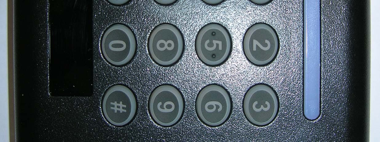
OQLGS3PIN
Jul 30, 2013PIN MT Reader GS3 OneProx
Equipment Class
DXX - Part 15 Low Power Communication Device Transmitter