OQL-P-PNLLow range proximity reader
PAC International Limited
Click to zoom
Application Details
- Equipment Class
- DCD - Part 15 Low Power Transmitter Below 1705 kHz
- Date of Grant
- Jan 12, 2003
- Application Purpose
- Original Equipment
- Date of Application
- Jan 12, 2003
- Equipment Note
- Low range proximity reader
- Frequency Range
- 0.15350000 - 0.15350000
- Company
- PAC International Limited
- Country
- United Kingdom
Documents & Files
Document Text
Text extracted from the exhibit documents filed with the FCC. Open a document above to read the original.
Users Manual
Data Sheet January 200315729 Ver 1.5 DRAFT D PAC Portico, 1 Lower Ragsdale Drive, Building 3, Suite 800, Monterey, California 93940 USA www.PACPortico.com This document is correct at the time of going to press. However, as part of our ongoing product enhancement program we reserve the right to make changes to the product and/or literature at any time without prior notice. PAC Readers Low Profile, Vandal Resistant and Panel Mount 2001Low Profile Reader-Black 2001WLow Profile Reader-White 2002Vandal Resistant Reader-Steel 2002WVandal Resistant Reader-Brass 2025Panel Mount Reader CAUTION These readers should only be used with systems that use PAC ID keys. For example, they should not be connected to an Easikey controller. Low ProfileVandal ResistantPanel Mount Items Enclosed Low profile readerVandal resistant readerPanel mount reader and head 4 terminal screws4 terminal screws4 terminal screws MOVMOVMOV Mounting backplate4 x 1¼" No. 8 VR screwsLexan window and backplate Label 2 x 1" No.6 self-tapping screws A special screwdriver (available separately) is required for the Vandal Resistant (VR) screws. Note The readers come with a 6-wire suppression lead that should be installed as described in this datasheet. This cable must be installed to comply with CE regulations. Dimensions H x W x D in/mm 3.94/100 x 3.46/88 x 0.47in/12 H x W x D in/mm 3.94/100 x 3.94/100 x 0.47/(12 H x W x D in/mm 3.62/92 x 2.44/62 x 0.59/15 Reader 2.36/60 x 2.36/60 x 0.47/12 Head Maximum Reading Range 2in/50mm0.4in/10mm0.4in/10mm 15729 Ver 1.5 DRAFT DPAC Readers Low Profile, Vandal Resistant and Panel Mount Page 2© 2003 Blick USA, Inc Installation CAUTIONS 1. The readers should not be mounted on metal. 2. The cable distance from controller to reader should not exceed the cable distance quoted in Section 0. 3. If using a Request to Exit switch, ensure that the wiring is not accessible if the reader is removed. 4. Ensure that the LED is always visible to the key holder. 5. If the reader is installed externally, the terminals on the rear of the reader must be sealed with a silicone compound to prevent corrosion. Low Profile Readers This reader comes in two parts, the reader itself (A) with 4 terminals and the backplate (B). The backplate has a rubber spacer at the rear. Mounting the Reader 1. The cable from the controller should be routed through the hole in the backplate. Leave enough cable exposed to allow easy wiring of the reader (at least 1 inch). Note: There is limited room between the reader and backplate. You should ensure there is a void large enough behind the backplate to accommodate the any excess on the suppression cable. 2. Mount the backplate to a flat surface using the No.6 screws provided - or a something suitable for the material to which the reader is being mounted. The two holes are 60mm apart. Use the top (round) hole first, and the lower (oval) hole to ensure the reader is straight. 3. Ensure that the reader cable is not connected to the controller. Wire the reader to the cable as described later in this data sheet and in the door controller Installation Manual 4. Push the reader, with the green LED to the top, onto the backplate, the fixing tabs on each side should snap into place. 5. Place label on front of reader. PAC Readers Low Profile, Vandal Resistant and Panel Mount15729 Ver 1.5 DRAFT D © 2003 Blick USA, IncPage 3 Removing the Reader The reader can be removed from the backplate by placing a small flat-bladed screwdriver into the apertures on each side of the backplate. Take care not to damage the reader or backplate. Vandal Resistant Readers This reader should be mounted using the vandal resistant screws provided. Note A special screwdriver (not supplied) is required to use these screws. Mounting the Reader 1. The cable from the controller should come to the rear of the reader. Leave enough cable exposed to allow easy wiring of the reader (at least 1 inch). Note: The terminals protrude ¼ in from the rear of the reader. You should ensure there is a void large enough (about 1 ½ in square and ¾ in deep) behind the reader to accommodate the terminals and excess suppression cable. 2. Ensure that the reader cable is not connected to the door controller. Wire the reader to the cable as described later in this data sheet and in the door controller Installation Manual. 3. Apply a silicone sealant to the terminals to protect against moisture if the reader is mounted outside. 4. Mount the reader to as flat and even a surface as possible. This will reduce the possibility of it being levered from the wall. Either use the Vandal Resistant screws provided, or other suitable fixings. The LED should be to the top. 15729 Ver 1.5 DRAFT DPAC Readers Low Profile, Vandal Resistant and Panel Mount Page 4© 2003 Blick USA, Inc Panel Mount Reader This reader is designed to be mounted in a steel panel (E) such as used in a door-entry system. There are two main units; the main module, a black rectangular unit, connected by a fixed length of cable to a reading head. The cable between the two parts is fixed, 24in/ 60mm long and should not be cut, extended or shortened. Panel Aperture The reading head is designed to fit a 1.57in/40mm square hole. Holes on the reading head, 1.89in/48mm between centres, accept M3 (metric) posts (F). The posts should be at least 0.59in/15mm long. The front cover (A) protrudes 0.10in/2.5mm through the hole. Locating the Main Module Mount the module in a convenient place behind the panel. The holes in each corner will accept No. 6 screws. Ensure that the module is close enough to the reader head to allow the panel to be removed without straining the cable. Wire the reader as seacribed in Section 0. Ensure there is sufficient space for any excess sppression cable. Mounting the Reading Head There are 4 components to the reading head: 1. Remove the protective film from the front lexan window (A). Mount on the studs so that the centre fits through the aperture, with the shallow slot to the bo…
Text truncated - open the document above for the full version.
Cover Letter(s)
Covering letter for FCC Form 731 Attachments 0.459 Request that submitted material be withheld from Public Inspection FCC ID OQL-P-PNL It is requested that the following exhibits be withheld from Public Inspection: • Operational Description • Schematic Diagram • Block Diagram • Internal Photos This information is considered to be PAC International proprietary and confidential. The unit is supplied fully encapsulated in hard potting - the design features are not evident from inspection hence reverse engineering is extremely problematic. This unit is believed to have a commercial advantage over our competition – revealing details of the design to our competitors would put us at a disadvantage. We therefore request that the above-listed items are withheld from public inspection. Shaun Byrne Principal Engineer PAC International Ltd
External Photos
EXTERNAL PHOTOS
ID Label/Location Info
EXTERNAL PHOTOS
ID Label/Location Info
IDENTIFICATION LABELS The labels below are fitted as shown in the photo. The unit is marketed under the model numbers 2025, K2025, 25455, 20455 and 20455/2 The labels are made of polycarbonate. The adhesive is 3M468 (or equivalent). The label quality and adhesion satisfies UL requirements. +V SIG VCA -V FIX BARCODE HERE Made in UK 614/5 INTERNATIONAL LTD Model No.: X Date Code: MPT 1337 WT LICENCE EXEMPT FCC ID: OQL-P-PNL cause undesired operation. This device complies with Part 15 of the FCC Rules. Operation is subject to the following two conditions: (1) this device may not cause harmful interference, and (2) this device must accept any interference received, including interference that may 1561/1 LABEL LOCATIONS
Test Report
Page 1 of 16 Member of the SGS Group (Société Générale de Surveillance) Registered in England No. 1193985. Registered Office: Inward Way, Rossmore Business Park, Ellesmere Port, Cheshire, CH65 3EN. SGS United Kingdom Ltd. International Electrical Approvals abc South Industrial Estate Bowburn Co. Durham DH6 5AD United Kingdom Tel: +44 (0) 191 377 2000 Fax: +44 (0) 191 377 2020 email: [email protected] Electromagnetic Compatibility Test of: RF Card Entry System Model Numbers: Refer to page 5 Applicant: PAC International Ltd Test Type: Compliance Test Specification: Test Result: FCC CFR47, parts 15.107/15.207, 15.109 and 15.209. Complied SGS Serial Number: DUR 24094.1/EMC/LS/02 Date of Receipt: 30 th May 2002 Date of Test(s): 30 th May 2002 – 24 th June 2002 Date of Issue: 10 th January 2003 Issue Number: 3 This report refers only to the sample submitted for test. This report shall not be reproduced except in full without the written approval of the testing laboratory. Test EngineerAuthorised Signatory L.SteelA. Reynard Technical Manager abc TEST REPORT Page 2 of 16 Issue Date:10 th January 2003 SGS Serial Number:DUR24094.1/EMC/LS/02 Issue Number: 3 CONTENTSPage Number 1. Client Information ........................................................................................................................... 3 2. Details Of Test Laboratory............................................................................................................. 3 3. Equipment Under Test (EUT) ........................................................................................................ 4 3.1 Identification Of EUT...................................................................................................................................................... 4 4. Test Specification, Methods and Procedures ............................................................................. 6 4.1 Test Specification(s) ...................................................................................................................................................... 6 4.2 Purpose Of Test............................................................................................................................................................. 6 4.3 Methods and Procedures............................................................................................................................................... 6 5. Deviations or Exclusions from the Test Specifications ............................................................. 7 6. Operation of the EUT During Testing / Configuration and Peripherals .................................... 7 6.1 Operation of EUT during testing. ................................................................................................................................... 7 6.2 Configuration and Peripherals ........................................................................................................................................ 7 7. Test Results .................................................................................................................................... 8 7.1 General Comments........................................................................................................................................................ 8 7.2 Modifications Made to the EUT...................................................................................................................................... 8 7.3 Summary of Test Results ............................................................................................................................................... 8 7.4Conducted Emissions Test Results – 15.107/15.207 ............................................................. 9 7.5Radiated Emissions Test Results – (15.109)........................................................................ 13 7.6Radiated Emissions Test Results – (15.209)........................................................................ 15 abc TEST REPORT Page 3 of 16 Issue Date:10 th January 2003 SGS Serial Number:DUR24094.1/EMC/LS/02 Issue Number: 3 1. Client Information Company Name: PAC International Ltd Address: 1 Park Gate Close, Bredbury, Stockport, SK6 2SZ. Contact Person: Shaun Byrne Telephone: 0161 406 3400 Facsimile: 0161 430 8658 2. Details Of Test Laboratory Company Name: SGS International Electrical Approvals. UKAS Accreditation Number: 1116 Address: South Industrial Estate, Bowburn, Co. Durham, DH6 5AD. Contact Persons: Mr Alan Reynard Telephone: 0191 377 2000 Facsimile: 0191 377 2020 abc TEST REPORT Page 4 of 16 Issue Date:10 th January 2003 SGS Serial Number:DUR24094.1/EMC/LS/02 Issue Number: 3 3. Equipment Under Test (EUT) 3.1Identification Of EUT Model Numbers: Refer to page 5 for details of individual components of the system. Unique Identifier: Refer to page 5. Description of EUT: RF Card Entry System Internal Clock Frequencies: Refer to Page 5. Supply Voltage: 120V ac to controller (Note: all other PAC parts obtain their power via the controller). Classification: Refer to page 5. abc TEST REPORT Page 5 of 16 Issue Date:10 th January 2003 SGS Serial Number:DUR24094.1/EMC/LS/02 Issue Number: 3 EUT System Diagram NOTE: When testing PAC part 25401 to sec. 15.209, only the signal ports on the diagram above were terminated. Ports 1,2,3 and 4 were unterminated (i.e. no other PAC items were connected to the controller) Component Model No. Serial No. DescriptionIntentional/ Unintentional Radiator? Highest Frequency Generated/Used 25566None4 door controllerUnintentional<108 MHz 25401NoneCard ReaderIntentional and Unintentional614 kHz 257431922376Wiegand InterfaceUnintentional<108 MHz 205591700593Access ProhibitorUnintentional<108 MHz 205581876054Alarm InterfaceUnintentional<108 MHz 213601801225Alarm Event Manager Unintentional<108 MHz 254551951674Card ReaderIntentional and Unintentional614 kHz 205921806250Card ReaderIntentional and Unintentional…
Text truncated - open the document above for the full version.
Test Report
Page 1 of 9 Member of the SGS Group (Société Générale de Surveillance) Registered in England No. 1193985. Registered Office: Inward Way, Rossmore Business Park, Ellesmere Port, Cheshire, CH65 3EN. SGS United Kingdom Ltd. International Electrical Approvals abc South Industrial Estate Bowburn Co. Durham DH6 5AD United Kingdom Tel: +44 (0) 191 377 2000 Fax: +44 (0) 191 377 2020 email: [email protected] Electromagnetic Compatibility Test of: RF Card Entry Reader Model Number: 25455 Applicant: PAC International Ltd Test Type: Compliance Test Specification: Test Result: FCC CFR47, part 15.209 (up-to 30 MHz) only. Complied SGS Serial Number: DUR 24094.6/EMC/LS/02 Date of Receipt: 14 th June 2002 Date of Test(s): 20 th June 2002 Date of Issue: 10 th January 2003 Issue Number: 3 This report refers only to the sample submitted for test. This report shall not be reproduced except in full without the written approval of the testing laboratory. Test EngineerAuthorised Signatory L.SteelA. Reynard Technical Manager abc TEST REPORT Page 2 of 9 Issue Date:10 th January 2003 SGS Serial Number:DUR24094.6/EMC/LS/02 Issue Number: 3 CONTENTSPage Number 1. Client Information ........................................................................................................................... 3 2. Details Of Test Laboratory............................................................................................................. 3 3. Equipment Under Test (EUT) ........................................................................................................ 4 3.1 Identification Of EUT...................................................................................................................................................... 4 4. Test Specification, Methods and Procedures ............................................................................. 5 4.1 Test Specification(s) ...................................................................................................................................................... 5 4.2 Purpose Of Test............................................................................................................................................................. 5 5. Deviations or Exclusions from the Test Specifications ............................................................. 6 6. Operation of the EUT During Testing / Configuration and Peripherals .................................... 6 6.1 Operation of EUT during testing. ................................................................................................................................... 6 6.2 Configuration and Peripherals ........................................................................................................................................ 6 7. Test Results .................................................................................................................................... 7 7.1 General Comments........................................................................................................................................................ 7 7.2 Modifications Made to the EUT...................................................................................................................................... 7 7.3 Summary of Test Results ............................................................................................................................................... 7 Full details of all tests can be found in the test results section of this report. ......................................................................... 7 7.4Radiated Emissions Test Results – 15.209............................................................................ 8 abc TEST REPORT Page 3 of 9 Issue Date:10 th January 2003 SGS Serial Number:DUR24094.6/EMC/LS/02 Issue Number: 3 1. Client Information Company Name: PAC International Ltd Address: 1 Park Gate Close, Bredbury, Stockport, SK6 2SZ. Contact Person: Shaun Byrne Telephone: 0161 406 3400 Facsimile: 0161 430 8658 2. Details Of Test Laboratory Company Name: SGS International Electrical Approvals UKAS Accreditation Number: 1116 Address: South Industrial Estate, Bowburn, Co. Durham, DH6 5AD. Contact Persons: Mr Alan Reynard Telephone: 0191 377 2000 Facsimile: 0191 377 2020 abc TEST REPORT Page 4 of 9 Issue Date:10 th January 2003 SGS Serial Number:DUR24094.6/EMC/LS/02 Issue Number: 3 3. Equipment Under Test (EUT) 3.1Identification Of EUT Model Number: 25455 Unique Identifier: 1975748 Description of EUT: RF Card Entry Reader Internal Clock Frequencies: (Maximum) 614 kHz Supply Voltage: 18V DC from a Controller (Controller supply = 120 V AC, 60 Hz) Classification: Intentional and Unintentional Radiator Accessories Supplied: 2100 Controller abc TEST REPORT Page 5 of 9 Issue Date:10 th January 2003 SGS Serial Number:DUR24094.6/EMC/LS/02 Issue Number: 3 4. Test Specification, Methods and Procedures 4.1Test Specification(s) Specification(s)Title FCC CFR 47 : October 1999 Part 15.209 only Code Of Federal Regulations 4.2Purpose Of Test To perform the radiated emissions test to the above specification in the frequency range 9 kHz to 30 MHz only, as requested by the client. 4.3Methods and Procedures The standard listed above refers to the following tests: - CFR 47 ClauseTest 15.209Radiated Emissions abc TEST REPORT Page 6 of 9 Issue Date:10 th January 2003 SGS Serial Number:DUR24094.6/EMC/LS/02 Issue Number: 3 5. Deviations or Exclusions from the Test Specifications There were no deviations from the test specifications. 6.Operation of the EUT During Testing / Configuration and Peripherals 6.1Operation of EUT during testing. Refer to individual test results sections for details of EUT operation during testing. 6.2Configuration and Peripherals The EUT was connected to a controller, (Manufacturer: PAC International, Model No: 25566, Serial No: Not supplied) in order to provide power to the EUT. The controller front panel was…
Text truncated - open the document above for the full version.
Test Report
Page 1 of 12 Member of the SGS Group (Société Générale de Surveillance) Registered in England No. 1193985. Registered Office: Inward Way, Rossmore Business Park, Ellesmere Port, Cheshire, CH65 3EN. SGS United Kingdom Ltd. International Electrical Approvals abc South Industrial Estate Bowburn Co. Durham DH6 5AD United Kingdom Tel: +44 (0) 191 377 2000 Fax: +44 (0) 191 377 2020 email: [email protected] Electromagnetic Compatibility Test of: RF Card Entry Reader Model Number: 25686 Applicant: PAC International Ltd Test Type: Compliance Test Specification: Test Result: FCC CFR47, part 15.209 Complied SGS Serial Number: DUR 24094/EMC/LS/02 Date of Receipt: 14 th June 2002 Date of Test(s): 14 th - 18 th June 2002 Date of Issue: 10 th January 2002 Issue Number: 3 This report refers only to the sample submitted for test. This report shall not be reproduced except in full without the written approval of the testing laboratory. Test EngineerAuthorised Signatory L.SteelA. Reynard Technical Manager abc TEST REPORT Page 2 of 12 Issue Date:10 th January 2003 SGS Serial Number:DUR24094/EMC/LS/02 Issue Number: 3 CONTENTSPage Number 1. Client Information ........................................................................................................................... 3 2. Details Of Test Laboratory............................................................................................................. 3 3. Equipment Under Test (EUT) ........................................................................................................ 4 3.1 Identification Of EUT...................................................................................................................................................... 4 4. Test Specification, Methods and Procedures ............................................................................. 5 4.1 Test Specification(s) ...................................................................................................................................................... 5 4.2 Purpose Of Test............................................................................................................................................................. 5 4.3 Methods and Procedures............................................................................................................................................... 5 5. Deviations or Exclusions from the Test Specifications ............................................................. 6 6. Operation of the EUT During Testing / Configuration and Peripherals .................................... 6 6.1 Operation of EUT during testing. ................................................................................................................................... 6 6.2 Configuration and Peripherals ........................................................................................................................................ 6 7. Test Results .................................................................................................................................... 8 7.1 General Comments........................................................................................................................................................ 8 7.2 Modifications Made to the EUT...................................................................................................................................... 8 7.3 Summary of Test Results ............................................................................................................................................... 8 7.4Radiated Emissions Test Results – 15.209 (9KHz – 30MHz) ................................................. 9 7.5Radiated Emissions Test Results – 15.209 (30MHz – 1000MHz) ........................................ 11 abc TEST REPORT Page 3 of 12 Issue Date:10 th January 2003 SGS Serial Number:DUR24094/EMC/LS/02 Issue Number: 3 1. Client Information Company Name: PAC International Ltd Address: 1 Park Gate Close, Bredbury, Stockport, SK6 2SZ. Contact Person: Shaun Byrne Telephone: 0161 406 3400 Facsimile: 0161 430 8658 2. Details Of Test Laboratory Company Name: SGS International Electrical Approvals UKAS Accreditation Number: 1116 Address: South Industrial Estate, Bowburn, Co. Durham, DH6 5AD. Contact Persons: Mr Alan Reynard Telephone: 0191 377 2000 Facsimile: 0191 377 2020 abc TEST REPORT Page 4 of 12 Issue Date:10 th January 2003 SGS Serial Number:DUR24094/EMC/LS/02 Issue Number: 3 3. Equipment Under Test (EUT) 3.1Identification Of EUT Model Number: 25686 Unique Identifier: 1951642 Description of EUT: RF Card Entry Reader Internal Clock Frequencies: (Maximum) 614 kHz Supply Voltage: 18V DC from a Controller (Controller supply = 120 V AC, 60 Hz) Classification: Intentional and Unintentional Radiator Accessories Supplied: 2100 Controller (9kHz – 30MHz) See section 6.2 (30MHz – 1000MHz) abc TEST REPORT Page 5 of 12 Issue Date:10 th January 2003 SGS Serial Number:DUR24094/EMC/LS/02 Issue Number: 3 4. Test Specification, Methods and Procedures 4.1Test Specification(s) Specification(s)Title FCC CFR 47 : October 1999 Part 15.209 only Code Of Federal Regulations 4.2Purpose Of Test To perform the radiated emissions test to the above specification in the frequency range 9kHz – 1000MHz as requested by the client. 4.3Methods and Procedures The standard listed above refers to the following tests: - CFR 47 ClauseTest 15.209Radiated Emissions (9kHz – 30MHz) 15.209Radiated Emissions (30MHz – 1000MHz) abc TEST REPORT Page 6 of 12 Issue Date:10 th January 2003 SGS Serial Number:DUR24094/EMC/LS/02 Issue Number: 3 5. Deviations or Exclusions from the Test Specifications There were no deviations from the test specifications. 6.Operation of the EUT During Testing / Configuration and Peripherals 6.1Operation of EUT during testing. Refer to individual test results sections for details of EUT operation during testing. 6.2Configuration and Periph…
Text truncated - open the document above for the full version.
Test Setup Photos
abc TEST REPORT Page 9 of 9 Issue Date:14 th November 02 SGS Serial Number:DUR24094.6/EMC/LS/02 Issue Number: 1 Radiated Emissions Test Configuration Radiated Emissions Environmental Conditions Power Supply (to controller) 120V AC, 60 Hz Temperature 13°C Relative Humidity 59% Barometric Pressure 976mb Radiated Emissions Measurement Uncertainties Frequency ± 200kHz Amplitude ± 4.6dB The uncertainties stated are calculated in accordance with the requirements of UKAS with a confidence level of 95%. Test Equipment Used Equipment TypeModel Number Loop AntennaEMCO 6502 Spectrum AnalyserHP8563E
Contact Information
Applicant
Shaun C Byrne(Controller Team Leader)
Technical Contact
PAC INTERNATIONAL LTDMike Cook
[email protected]44 161 4063400
1 PARK GATE CLOSE, BREDBURY · STOCKPORT, CHESHIRE · United Kingdom
Non-Technical Contact
PAC INTERNATIONAL LTDRobert W Harvey
[email protected]44 161 4063400
Test Firm
SGS United Kingdom Ltd.Stephen Thompson
Technical Specifications
| # | Rule Parts | Frequency Range | Power Output |
|---|---|---|---|
| 1 | 15C | 0.1535 MHz - 0.1535 MHz | - |
Other Applications from PAC International Limited
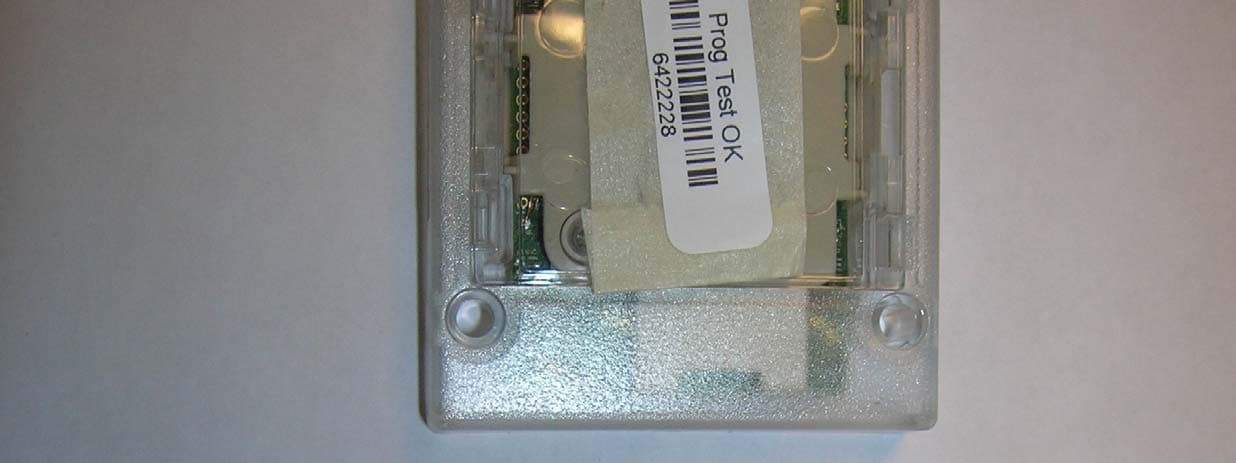
OQLGS3LFP
Aug 01, 2013Panel LF Reader GS3 OneProx
Equipment Class
DCD - Part 15 Low Power Transmitter Below 1705 kHz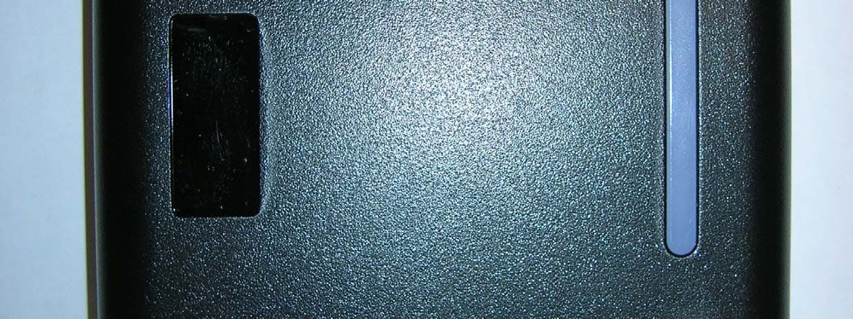
OQLGS3LFS
Aug 01, 2013Standard LF Reader GS3 OneProx
Equipment Class
DCD - Part 15 Low Power Transmitter Below 1705 kHz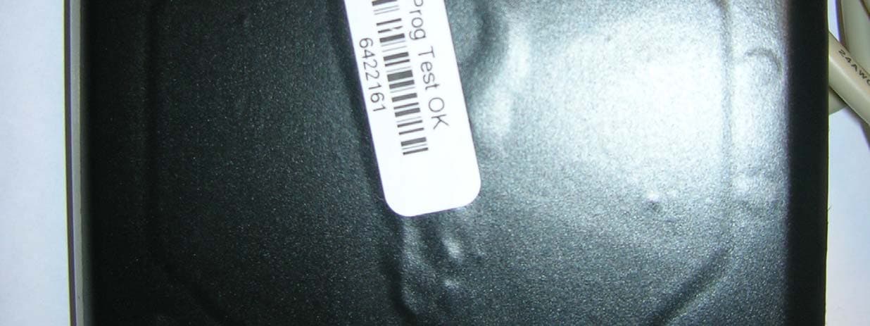
OQLGS3LFV
Aug 01, 2013Vandal LF Reader GS3 OneProx
Equipment Class
DCD - Part 15 Low Power Transmitter Below 1705 kHz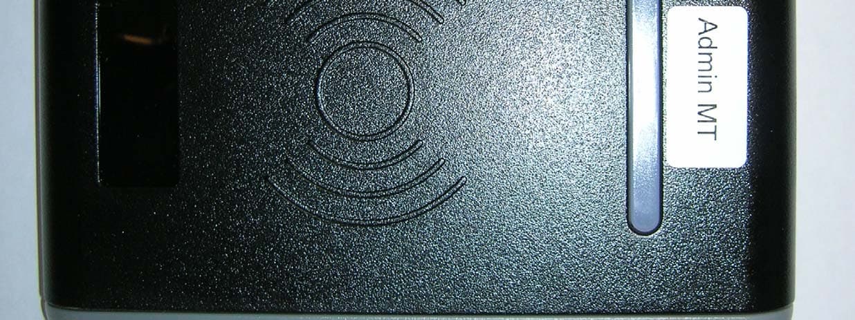
OQLGS3MTA
Jul 31, 2013Admin MT Reader GS3 OneProx
Equipment Class
DXX - Part 15 Low Power Communication Device Transmitter
OQLGS3PIN
Jul 30, 2013PIN MT Reader GS3 OneProx
Equipment Class
DXX - Part 15 Low Power Communication Device Transmitter