OQL-R-DMLow Range Proximity Reader
PAC International Limited
Click to zoom
Application Details
- Equipment Class
- DCD - Part 15 Low Power Transmitter Below 1705 kHz
- Date of Grant
- Jan 31, 2005
- Application Purpose
- Original Equipment
- Date of Application
- Jan 31, 2005
- Equipment Note
- Low Range Proximity Reader
- Frequency Range
- 0.13300000 - 0.13300000
- Company
- PAC International Limited
- Country
- United Kingdom
Documents & Files
Document Text
Text extracted from the exhibit documents filed with the FCC. Open a document above to read the original.
Users Manual
sdsdy KeyPAC Classic and Designer Readers Installation Guide KeyPAC Classic und Designer Lesers Installationsanleitung KeyPAC Classic et Designer Lecteurs Guide d'installation KeyPAC Classic y Designer Lectores Guía de instalación KeyPAC Classic och Designer Läsares Installationsanvisningar KeyPAC Classic en Designer Lezers Installatiehandleiding 17980v2.1 Jan 05 2 17980v2.1 Reader Part Numbers / Leser Teilnummern / Numéros de pièces du lecteur / Números de pieza del lector / Läsarens Artikelnummer/ Lezer Productnummers KeyPAC Classic Mullion 20069 KeyPAC Designer Mullion 20065 Card/Token Part Numbers / Karten/Token Teilnummern / Numéros de pièces de carte/fiche / Números de pieza de la tarjeta/ficha / Kort/Nyckel Artikelnummer / Kort/Penningen Productnummers KeyPAC card/karten/carte/tarjeta/kort/kort x10 21030 KeyPAC card with Magstripe/kartenMit Magnetstreifen/carte avec bande magnétique/tarjeta con banda magnética/kort med magnetremsa x10 21031 KeyPAC token/fiche/ficha/nyckel/penningen x10 20250 Specification / Spezifikation / Spécification / Especificaciones / Specifikation / Specificaties Card Range Token Range Power Current KeyPAC Mullion Classic up to 2.0in/50mm up to 1.1in/30mm +10.5 to +28V <100mA KeyPAC Mullion Designer up to 3.5in/90mm up to 1.9in/50mm +10.5 to +28V <100mA Temperature / Temperatur / Température / Temperatura / Temperatur / Temperatuur Operating -20 to +55ºC/-3 to 130ºF; Storage -30 to +80ºC/-35 to175ºF Humidity / Feuchtigkeit / Humidité / Humedad / Luftfuktighet / Vochtigheid Operating 10-85% RH at 30 ± 2ºC/85 ± 4ºF for 24 hours Ingress Protection / Eindringschutz / Protection contre l'entrée / Protección de acceso / Kapsling / Stofbescherming IP 66 FCC KeyPAC Mullion Classic FCC ID OQL-R-P KeyPAC Mullion Designer FCC ID OQL-R-DM This device complies with part 15 of the FCC Rules. Operation is subject to the following two conditions: (1) This device may not cause harmful interference, and (2) this device must accept any interference received, including interference that may cause undesired operation. In compliance with FCC requirement 15.27 no special accessories are required in order to comply with part 15 of the FCC regulations. Changes or modifications not expressly approved by PAC International could void the user's authority to operate the equipment. 17980v2.1 3 Connections/ Anschlüsse / Connexions / Conexiones / Anslutningar / Voedingsaansluitingen All dimensions ins/mm / Alle Ausmaße in zoll/mm / Toutes dimensions en pce/mm / Todas las dimensiones en pulg./mm /Alla mått i tum/mm / Alle afmetingen inch/mm KeyPAC Classic Mullion KeyPAC Designer Mullion A 10.5-28V B SIG/D1/DATA/SIGNAL C LED D GND/0V E D0/CLK F Tamper / Sabotage / Effraction / Manip.fraud. / Manip / Tamper G Sounder / Signaltongeber / Alarme sonore / Sonido / Ljudsignal/Alarm H Not used / Nicht verwendet / N'est pas utilisé /No se utiliza / Används inte/Niet gebruikt Output Format Selection / Wahl des Ausgabeformats / Sélection de format de sortie / Selección de formato de salida / Val av utdataformat / Selectie van uitvoerformaat Connections/Anschlüsse/ Connexions/Conexiones/ Verbindingen/Anslutningar No. of flashes/ Zahl der Blinkvorgänge/ Nb. de clignotements/ Núm. de destellos/Aantal flitsen/ Antal blinkningar PAC (default/vorgabe/ standaard/ por defecto) C-B - 0 Wiegand 26-bit C-E - 1 Wiegand 34-bit C-B G-E 2 Magstripe/gnetstreifen/ magnetremsa - G-E 4 Barcode C-E G-B 5 4 17980v2.1 Installation 1. Ensure your product comes with the items indicated on page 2; if not please contact your dealer. 2. Mounting on metal surfaces will reduce the reader range. 3. Mount readers >3ft/1m apart. 4. For outside readers, use corrosion-resistant fixings and silicone-sealant on terminals. 5. The MOV should be fitted across the power terminals of the lock. 6. After installation, fill the connector well with silicone to seal it. PAC recommend a high-quality sealant like Dow Corning Type 732. Output Format Selection 1. Short together the connections indicated in the table on page 3. 2. Apply power for 2 seconds 3. Separate all connections. 4. Re-apply power. 5. LED flashes to indicate ouput format set in the table on page 3. Installation 1. Überprüfen Sie, ob Ihr Produkt die einzelteile angezeigt auf Seite 2. Wenn nicht, wenden Sie sich bitte an Ihren Händler. 2. Die Befestigung an den Metalloberflächen verringert die Leserstrecke. Der Paneelen-Leser ist für den Einbau in einem quadratischen Ausschnitt (40 mm Kantenlänge) in einem Edelstahlblech bestimmt. 3. Leser im Abstand von > 3 Fuß/1 m anbringen. 4. Für Leser im Freien korrosionsbeständige Befestigungselemente und Silikondichtungsmittel an den Anschlüssen verwenden. 5. Der MOV sollte über die Stromanschlüsse des Schlosses angebracht werden. 6. Nach der Installation den Stecker vollständig mit Silikon füllen, um ihn zu versiegeln. PAC empfehlen ein hochwertiges Dichtungsmittel wie Dow Corning Art 732. Wahl des Ausgabeformats 1. Die Anschlüsse wie auf der nachfolgenden Tabelle angegeben auf Seite 3 miteinander kurzschließen. 2. 2 Sekunden lang Strom anlegen. 3. Alle Anschlüsse trennen. 4. Nochmals Strom anlegen. 5. Die LED Blitze, zum des ouput Formats anzuzeigen stellten in die Tabelle auf Seite 3 ein. English Deutsch 17980v2.1 5 Installation 1. Vérifiez que votre produit contient toutes les articles indiqués à la page 2. En cas de pièce manquante , contactez votre distributeur. 2. Le montage sur des surfaces en métal réduira la gamme de lecteur. 3. Monter les lecteurs à de telle sorte qu'ils soient espacés d'1 m. 4. Pour les lecteurs extérieurs, utiliser des fixations résistantes à la corrosion et du silicone sur les bornes. 5. Le MOV (varistor à oxyde métallique) doit être installé en travers des bornes d'alimentation du verrou. 6. Après l'installation, bien remplir le connecteur de silicone pour l'étanchéiser. PAC recommandent un mastic de haute qualité comme le Dow Corning type 732. Sélection de format de sortie 1. Court-circuiter les connexions i…
Text truncated - open the document above for the full version.
Attestation Statements
25 th January 2005 Federal Communications Commission 7435 Oakland Mills Road Columbia, MD 21046 We the undersigned, hereby certify that, in the case of individual applicant, he or she is not subject to a denial of federal benefits pursuant to section 5301 of the Anti-Drug Abuse Act of 1988, 21 USC 853a or in the case of non-individual applicant (e.g. corporation, partnership or other unincorporated association), no party to the applicant is subject to a denial of federal benefit pursuant to that action. Sincerely, Michael Kenneth Cook Embedded Systems Development Manager Phone: +44 (0)161 406 3576 Fax: +44 (0)161 494 6526
Cover Letter(s)
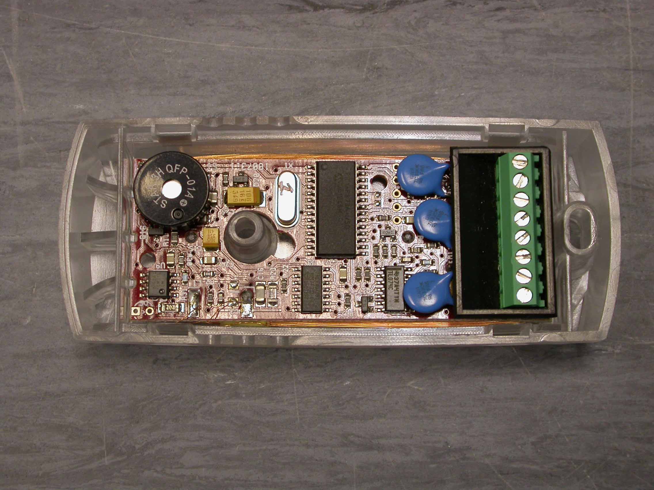
Covering letter for FCC Form 731 Attachments 0.459 Request that submitted material be withheld from Public Inspection FCC ID OQL-R-DM It is requested that the following exhibits be withheld from Public Inspection: • Operational Description – “Operational Description.doc” • Schematic Diagram – “PR001 Schematics.pdf” • Block Diagram – “Block Diagram.doc” • Internal Photos – “Internal Photos.doc” This information is considered to be PAC International proprietary and confidential. The unit is supplied fully encapsulated in hard potting (two part polyurethane, 50 Shore D hardness). This protects the PCB and coil against deliberate damage and it is not practical, even with tools, to remove the potting without destroying the PCB - the design features are not evident from inspection hence reverse engineering is extremely problematic. This unit is believed to have a commercial advantage over our competition – revealing details of the design to our competitors would put us at a disadvantage. We therefore request that the above-listed items are withheld from public inspection. Robert Harvey CEng MIEE Technical Director PAC International Ltd
External Photos
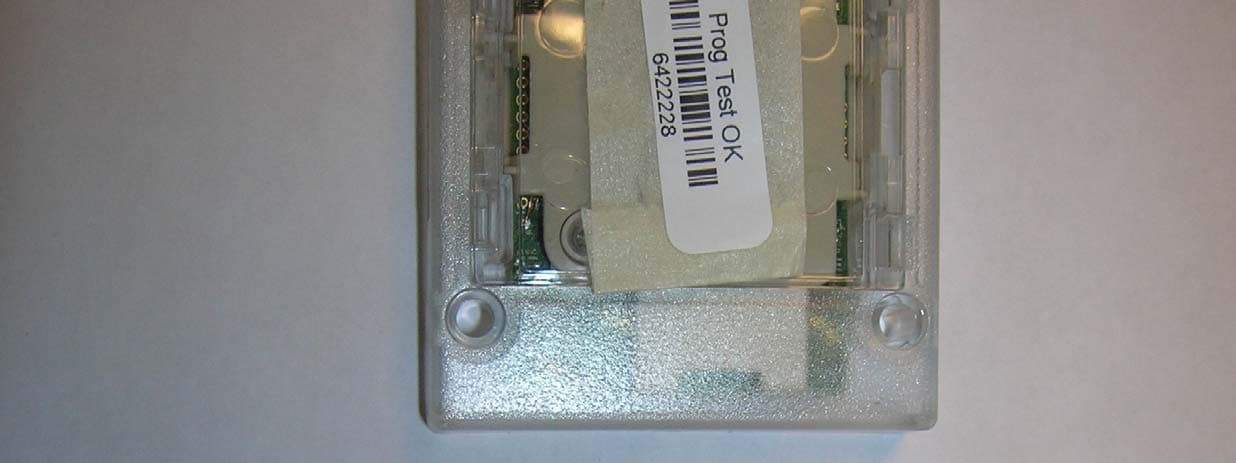
External Back External Front
ID Label/Location Info
IDENTIFICATION LABELS The labels below are fitted as shown in the photo. The unit is marketed under various part numbers, all having common hardware and firmware but differing in cosmetic aspects such as color, housing style etc. All units bearing the Model Number “PR001” covered by the scope of this submission. The labels are made of polycarbonate. The adhesive is 3M468 (or equivalent). The label quality and adhesion satisfies UL requirements. Labels UL approval will be sought. Once the unit is approved, the UL logo and details will also be added to the label. The labels are made of polycarbonate. The adhesive is 3M468 (or equivalent). The label quality and adhesion satisfies UL requirements. Front Label Rear Labels LABEL POSITION (FRONT) LABEL POSITION (REAR)
Test Report
Test of: Mullion Designer Reader Model Number: PROO1 PAC International Applicant: Test Type: Compliance Test Specification: FCC CFR47 October 1 2003, parts 15.209 (below 30MHz), 15.207, and 15.109 Class A (above 30M Hz) SGS Serial Number: DUR41974A/3/EMC/CL/O4 Date of Receipt: 10th May 2004 Date of Testis): 1 Th May to 15th July 2004 Date of Issue: 3rd September 2004 Issue Number: 1 This report is issued by the Company subject to its General Conditions of Service available upon request and accessible at www.sgs.com. Attention is drawn to the limitations of liability, indemnification, jurisdictional, representative restrictions of test samples and sample retention policies defined therein. This report refers only to the sample submitted for test. This report shall not be reproduced except in full without the written approval of the testing laboratory. ,11 ;f.;t:: Test ~.~.~~/I C. Levy SGS United Ki~gdom Ltd Page 1 of 17 Unit 10 Bowburn South Industrial Estate Bowburn Co. Durham DH6 5AD t +44 (0)191 377 2000 f +44 (0)191 377 2020 wwwsgs.com --- Membe, of the SGS G,oup ISociete Gene,e'e de Surveillance) Registered in Englend No: 1193985 Registered Office: Rossmore Business Park Ellasmefe Port Cheshire CH653EN Authorised Sig\lnatory A. Reynard Technical Manager TEST REPORT Page 2 of 1 7 Issue Date:3rd September 2004 SGS Serial Number:DUR41974A/3/EMC/CL/04 Issue Number: 1 CONTENTS Page Number 1 Client Information '."""""""""'."' 3 2. Details Of Test Laboratory 3 3. Equipment Under Test (EUT) 3.1 Identification OfEUT 4 4 4.Test Specification. Methods and Procedures 4 4.1 Test Specification(s) 4 4.2 Purpose Of Test 4 4.3 Methods and Procedures 5 Deviations or Exclusions from the Test Specifications 6 5.6. Operation of the EUT During Testing I Configuration and Peripherals 7 6.1 Operation of EUTduring testing 7 6.2 Configuration and Peripherals 7 Test Results 77. 1 General Comments.. 7 7.2 Modifications Made to the EUT 7 7.3 Summary of Test Results 8 7.4 Radiated Emissions Test Results 9 7.5 Conducted Emissions Test Results 14 7 Issue Date:3rd September 2004 SGS Serial Number:DUR41974A/3/EMC/CL/04 Issue Number: 1 TEST REPORT Page 4 of 1 7 3. Equipment Under Test (EUT) 3.1Identification Of EUT 4. Test Specification, Methods and Procedures Test Specificationls) 4.14.2 Purpose Of Test To perform the relevant tests and assess the product for compliance with the above specifications. Issue Date:3rd September 2004 SGS Serial Number:DUR41974A/3/EMC/CL/04 Issue Number: 1 TEST REPORT Page 5 of 1 7 4.3Methods and Procedures The standards listed on the previous page refer to the following tests: - CFR 47 Clause Test 15.209 Radiated Emissions (Below 30MHz) 1 5.1 09 Radiated Emissions Class A (Above 30M Hz) 15.207 Conducted Emissions TEST REPORT Page 6 of 1 7 Issue Date:3rd September 2004 SGS Serial Number:DUR41974A/3/EMC/CL/04 Issue Number: 1 5. Deviations or Exclusions from the Test Specifications There were no deviations from the test specifications. Issue Date:3rd September 2004 SGS Serial Number:DUR41974A/3/EMC/CL/04 Issue Number: 1 TEST REPORT Page 7 of 1 7 6.Operation of the EUT During Testing / Configuration and Peripherals 6.1Operation of EUT during testing. Refer to individual test results sections for details of EUT operation during testing. 6.2Configuration and Peripherals The EUT was connected to a controller during the EMC tests. Test Results 7 7.1 General Comments The test methods used are referred to in the individual test results sections of this test report. Modifications Made to the EUT 7.2 No modifications were made to the EUT during the testing process. TEST REPORT Page 8 of 1 7 Issue Date:3rd September 2004 SGS Serial Number:DUR41974A/3/EMC/CL/04 Issue Number: 1 7.3Summary of Test Results CFR 47 Clause Test Result 15.209 Radiated Emissions (below 30M Hz) Complied 1 5.1 09 Radiated Emissions (above 30M Hz) Complied Class A 15.207Conducted Emissions Complied Result In the configuration tested, the EUT complies with the requirements of Clauses 15.209, 15.109 and 15.207 of CFR 47: October 2003. Full details of all tests can be found in the test results section of this report. Issue Date:3rd September 2004 SGS Serial Number:DUR41974A/3/EMC/CL/04 Issue Number: 1 TEST REPORT Page 9 of 17 7.4 Radiated Emissions Test Results Operating Mode The compliance test was performed without a card on the reader whilst connected to the controller. Test Results Note: The tables indicate the compliance measurement when the measurements are performed on the open area test site. Note: Measurements above the 10th harmonic of the fundamental carrier (134 kHz) were assessed against the general radiated emission limits applicable to the incorporated digital device (15.109). The Class A digital device limits were used. Quasi Peak Measurements 9 kHz-3D MHz Quasi Peak Measurement (dB~V/m) Frequency (MHz) Measurement distance * (m) limit (dB~V/m) 4.78 -13.29 -13.34 300 30 30 25.1 29.54 29.54 0.1341 7.3400 28.000 The test was performed at 3m and the measurements were corrected using an extrapolation factor of 40dB/decade. Issue Date:3rd September 2004 SGS Serial Number:DUR41974A/3/EMC/CL/04 Issue Number: 1 Frequency (MHz) Quasi-Peak Measurement (dBI-lV/m) Measurement distance* (m) Antenna Polarity (Horizontal/Vertical) Limit (dBj.lV/m) 10 10 10 Horizontal Horizontal Horizontal Horizontal Horizontal Horizontal Horizontal Horizontal Horizontal Horizontal Horizontal Horizontal Horizontal Horizontal Horizontal Horizontal ' Horizontal ' Horizontal ' Horizontal ' Horizontal . Horizontal ' Horizontal ' 39.0 39.039.039.043.543.543.543.543.543.543.543.543.543.5 46.4 46.4 46.4 46.4 46.4 46.4 46.4 46.4 * The test was performed at 3m and the measurements were corrected using an extrapolation factor of 20dB/decade. TEST REPORT Page 11 of 17 Issue Date:3rd September 2004 SGS Serial Number:DUR41974A/3/EMC/CL/04 Issue Number: 1 Quasi Peak Measurements 30 -1000 MHz Frequency (MHz) Quasi-Peak Measurement (dBIlV) Antenna Polarity (Horizo…
Text truncated - open the document above for the full version.
Test Setup Photos
Issue Date:3rd September 2004 SGS Serial Number:DUR41974A/3/EMC/CL/04 Issue Number: 1 Issue Date:3rd September 2004 SGS Serial Number:DUR41974A/3/EMC/CL/04 Issue Number: 1 TEST REPORT Page 13 of 17 Radiated Emissions Environmental Conditions Power Supply (to controller) 120 V 60 Hz (controller supply) 20°C 42% 1008mb Temperature Relative Humidity Barometric Pressure Radiated Emissions Measurement Uncertainties Frequency Amplitude :t 200kHz :t 4.6dB The uncertainties stated are calculated in accordance with the requirements of UKAS with a confidence level of 95%. Test Equipment Used Equipment Type Model NumberLast Calibration Date EMCO3109 EMCO3146 28/3/3 27/3/3 Calibration Interval 2 Years 2 Years EMCO 6502 Anritsu MS2613B HP8573B 23/4/3 1 5/8/04 1 5/8/04 2 Years 1 Year 1 Year Biconical Antenna Log Periodic Antenna Antenna Spectrum Analyser Hewlett Packard Receiver System TEST REPORT Page 16 of 17 Issue Date:3'd September 2004 SGS Serial Number:DUR41974A/3/EMC/CL/04 Issue Number: 1 Conducted Emissions Test Configuration Conducted Emissions Environmental Conditions 120V60Hz 23°C 36% 1008mb Power Supply (to controller) Temperature Relative Humidity Barometric Pressure Conducted Emissions Measurement Uncertainties Frequency Amplitude :t 200kHz :t 3.0dB The uncertainties stated are calculated in accordance with the requirements of UKAS with a confidence level of 95%. TEST REPORT Page 1 7 of 1 7 Issue Date:3rd September 2004 SGS Serial Number:DUR41974A/3/EMC/CL/04 Issue Number: 1 Test Equipment Used Equipment Type Model Number Last Calibration Date LISN (50m 2/7/04 Calibration Interval 1 Year Thurlby Thandar TTi 1 600 LHR7000 Version 6.00b 14/4/04 N/A N/A 1 Year N/A N/A Chase Receiver Software SGS Screened Room
Contact Information
Applicant
Shaun C Byrne(Controller Team Leader)
Technical Contact
PAC International LtdMichael Cook
[email protected]44 161 4063400
1 Park Gate Close · Stockport · United Kingdom
Non-Technical Contact
PAC InternationalRobert Harvey
[email protected]44 161 4063400
Test Firm
SGS United Kingdom Ltd.Stephen Thompson
Technical Specifications
| # | Rule Parts | Frequency Range | Power Output |
|---|---|---|---|
| 1 | 15C | 0.133 MHz - 0.133 MHz | - |
Other Applications from PAC International Limited
OQLGS3LFP
Aug 01, 2013Panel LF Reader GS3 OneProx
Equipment Class
DCD - Part 15 Low Power Transmitter Below 1705 kHz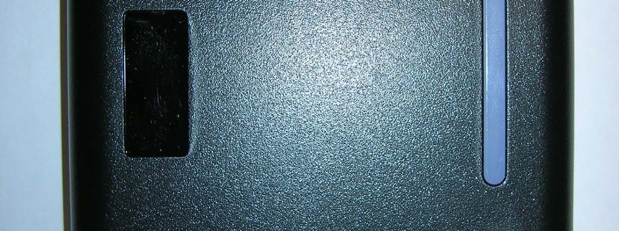
OQLGS3LFS
Aug 01, 2013Standard LF Reader GS3 OneProx
Equipment Class
DCD - Part 15 Low Power Transmitter Below 1705 kHz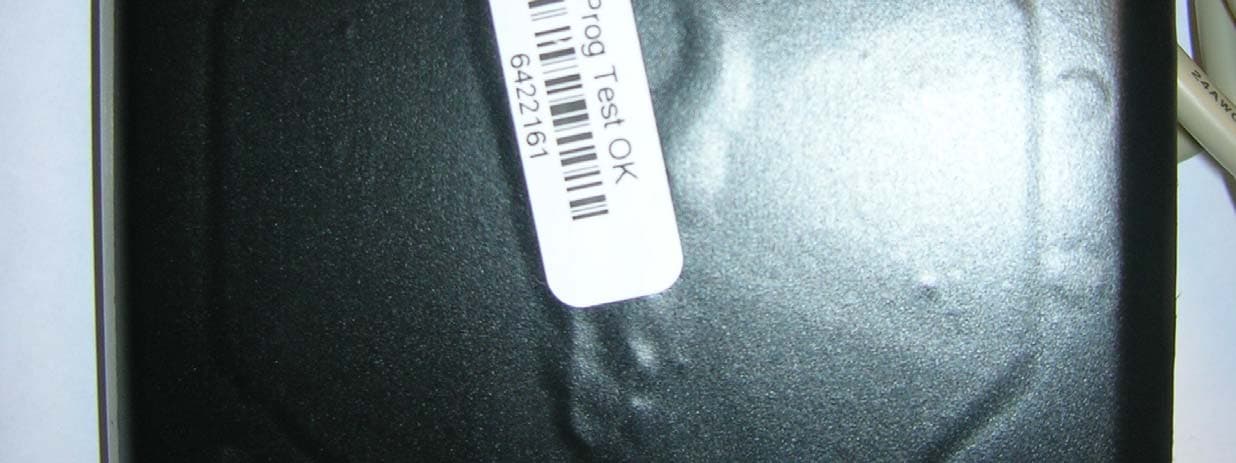
OQLGS3LFV
Aug 01, 2013Vandal LF Reader GS3 OneProx
Equipment Class
DCD - Part 15 Low Power Transmitter Below 1705 kHz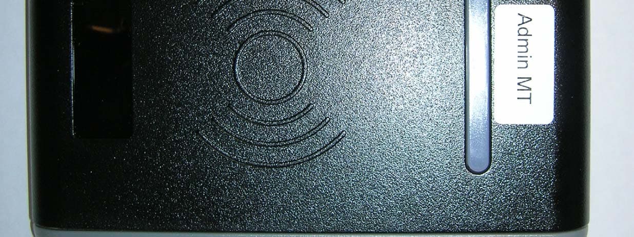
OQLGS3MTA
Jul 31, 2013Admin MT Reader GS3 OneProx
Equipment Class
DXX - Part 15 Low Power Communication Device Transmitter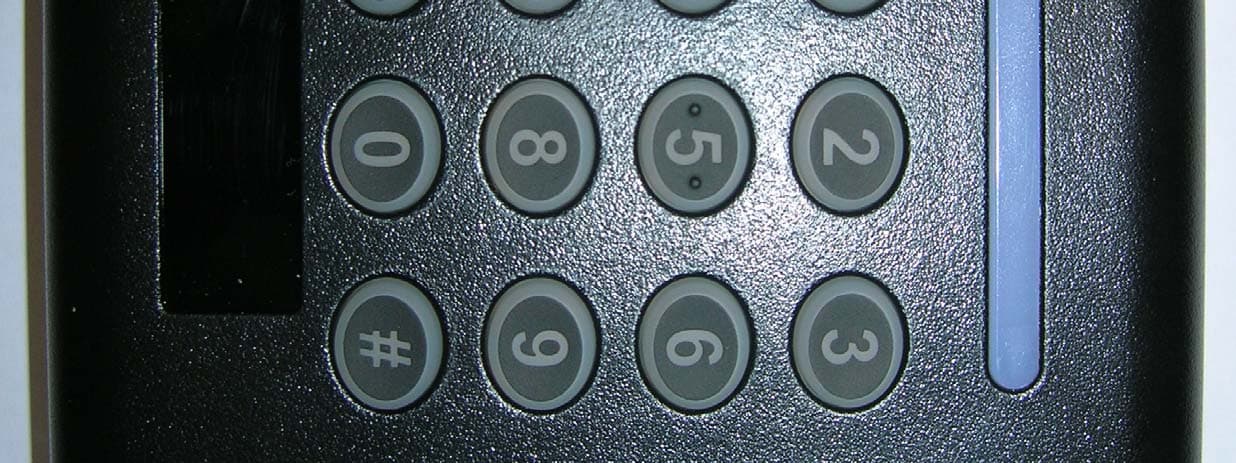
OQLGS3PIN
Jul 30, 2013PIN MT Reader GS3 OneProx
Equipment Class
DXX - Part 15 Low Power Communication Device Transmitter