OQT28ETP-FE-0228 GHz Fast Ethernet Wireless Transceiver
Triton Network Systems, Inc.
Click to zoom
Application Details
- Equipment Class
- TNB - Licensed Non-Broadcast Station Transmitter
- Date of Grant
- Oct 23, 2000
- Application Purpose
- Original Equipment
- Date of Application
- Oct 23, 2000
- Equipment Note
- 28 GHz Fast Ethernet Wireless Transceiver
- Frequency Range
- 27525.00000000 - 28325.00000000
- Company
- Triton Network Systems, Inc.
- Country
- United States
Documents & Files
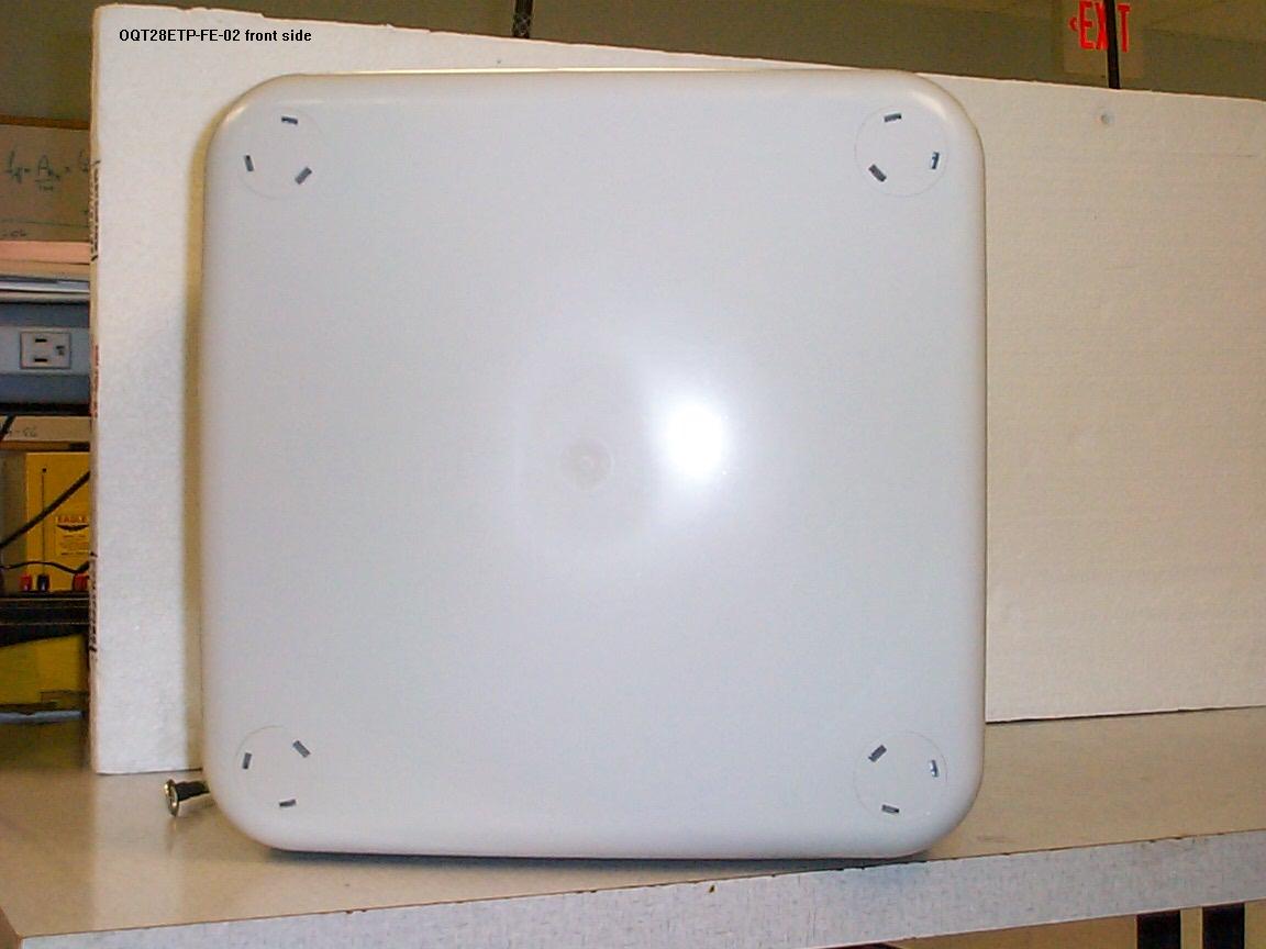
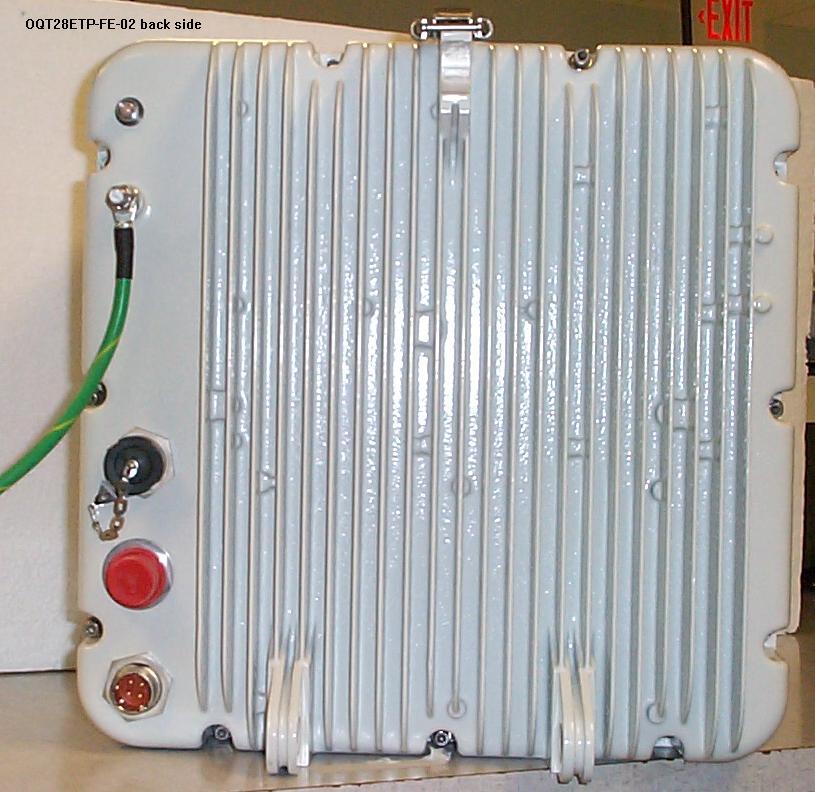
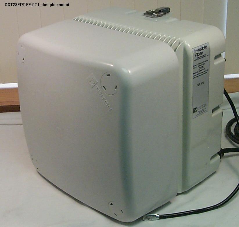
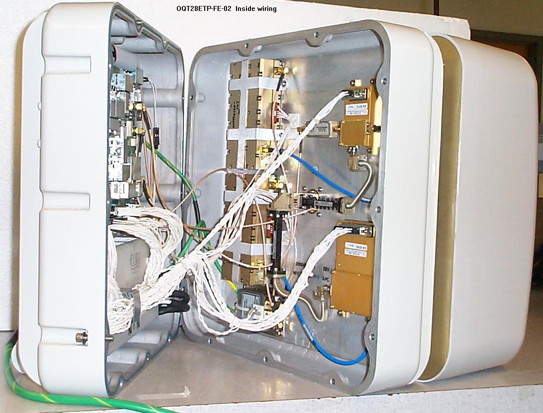
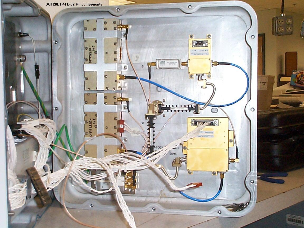
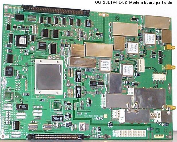
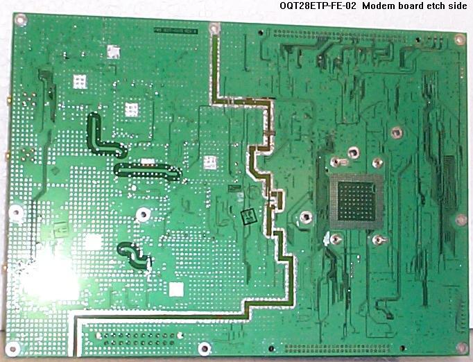
Document Text
Text extracted from the exhibit documents filed with the FCC. Open a document above to read the original.
Users Manual
Invisible Fiber TM Unit Installation Guide for 28 GHz 100 Mbps Internet Applications Part No. 5128002-0001 Release No. 1.0, February 2000 © 1999 Triton Network Systems, Inc. All Rights Reserved. Notice of Disclaimer The information and specifications provided in this document are subject to change without notice. The Warranty(s) that accompany Triton Network Systems, Inc., products are set forth in the sales agreement/contract between Triton Network Systems, Inc., and its customer. Please consult the sales agreement for the terms and conditions of the Warranty(s) provided by Triton Network Systems, Inc. To obtain a copy of the Warranty(s), contact Triton Network Systems, Inc., the Marketing Group at +1-407-903-0975 or +1-407-903-0997 (FAX). The information provided in this Triton Network Systems, Inc., document is provided “as is” without warranty of any kind, either expressed or implied, including, but not limited to, the implied warranties of merchantability, fitness for a particular purpose, or non-infringement. Some jurisdictions do not allow the exclusion of implied warranties, so the above exclusion may not apply to you. In no event shall any Triton Network Systems, Inc., company be liable for any damages whatsoever— including special, indirect, consequential or incidental damages or damages for loss of profits, revenue, use, or data whether brought in contract or tort, arising out of or connected with any Triton Network Systems, Inc., Document or the use, reliance upon or performance of any material contained in or accessed from this Triton Network Systems, Inc. document. Triton Network Systems’ license agreement may be provided upon request. Additional Terms and Conditions will be finalized upon negotiation of a purchase. Trademark Information Invisible Fiber™ is a trademark of Triton Network Systems, Inc. SmartBits™ and SmartApplications™ are a trademark of Netcom Systems Inc. All other brand or product names are trademarks or registered trademarks of their respective companies or organizations. Part Number: 5128002-0001 28 GHz 100 Mbps Internet IFU Installation - R1.0iii Contents Contents ............................................................................................. iii List of Figures ................................................................................... vii List of Tables ..................................................................................... ix About This Book ............................................................................... xi Purpose of This Book .................................................................................... xi Intended Audience ......................................................................................... xi Format of This Book ..................................................................................... xii Conventions Used in This Book ................................................................... xii Contacting Triton Network Systems, Inc. ...................................................xiii Warnings and Safety Guidelines .....................................................xv Conventions .................................................................................................. xv Risk of Personal Injury from Electrical Shock ............................................ xvi Risk of Personal Injury from Fiber Optics ................................................... xvi Risk of Personal Injury from Radio Frequency Energy Exposure .............. xvi Other Risks of Personal Injury .................................................................... xvii Risk of Service Interruption .......................................................................xviii Other Precautions ......................................................................................... xix Avertissements et consignes de sécurité ........................................ xxi Conventions ................................................................................................. xxi Risque de lésions corporelles provoquées par la décharge électrique ........ xxii iv© 1999 Triton Network Systems, Inc. All Rights Reserved. Risque de lésions corporelles provoquées par les câbles à fibres optiques .............................................................................................xxii Risque de lésions corporelles provoquées par l’exposition de l’énergie radiofréquences ..........................................................................................xxiii Autres risques des lésions corporelles .......................................................xxiii Risque d’interruption de service ................................................................ xxiv Autres mises en garde ................................................................................. xxv Chapter 1 — Installation Overview .............................................. 1-1 Installation Overview ...................................................................................1-1 Site Engineering Folder .........................................................................1-1 IFU Link Manager .......................................................................................1-2 Power Source ...............................................................................................1-2 Cabling .........................................................................................................1-2 Power Cable ..........................................................................................1-2 Alarm Cable ..........................................................................................1-2 Fiber Optic Cable ..................................................................................1-3 System Grounding and Surge Protection .....................................................1-3 Earth Ground ........................................................................…
Text truncated - open the document above for the full version.
Cover Letter(s)
Letter of Agency I, an officer of Triton Network Systems, Inc. do hereby authorize Intertek Testing Services to act on our behalf in front of the Federal Communication Commission with respect to all matters relating to certification of equipment under Part 101 of the FCC Rules until further notice. The application certifies that, in case of an individual applicant, he or she is not subject to a denial of federal benefits, that includes FCC benefits, pursuant to Section 5301 of the Anti-Drug Abuse Act of 1988, 21 U.S.C. 853(a), or, in the case of a non-individual applicant (e.g. corporation, partnership or other unincorporated association), no party to the application is subject to a denial of federal benefits, that includes FCC benefits, pursuant to that section. Michael Clark Vice President, Engineering Triton Network Systems, Inc. 8529 SouthPark Circle, 4 th Floor Orlando, FL 32819 August 20, 1999
ID Label/Location Info
Orlando, FL 32819, USA 407 – 903 – 0900 Model #: TNS-28-ETP-FE-XXX Part #: Serial #: XXXXXXXXX Rev: Volts: -48 VDC Amps: 5 A Hz: DC Date of Manufacture: XX/XX/XX FCC ID: OQT28ETP-FE-02 This device complies with Part 15 of the FCC rules. Operation is subject to the following two conditions: (1) this device may not cause harmful interference, and (2) this device must accept any interference received, including interference that may cause undesired operation. This device complies with the FCC Parts 101, 15B. Conforms to UL Std 50 (NEMA 4X), UL Std 1950. 9901046 www.triton-network.com
Operational Description
This information is furnished under the confidentiality request. 2.1033(c)(8) DC voltage/currents of final RF stage DC voltage/currents of final RF stage - both radios (FE and SONET) it is 6VDC @ 3.5A.
Operational Description
2.1033(c)(13) Digital Modulation Description Fast Ethernet - The combined payload data and control data are modulated using 8-PSK modulation. 100 Mbps FE IFU uses a 8-level Phase Shift Keying (8-PSK) modulation scheme. In 8-PSK modulation, the phase of the RF carrier is modulated such that each point of the constellation represents a particular phase of the RF carrier. The amplitude of the RF carrier remains constant. The spectrum of the modulated waveform fits within the spectral masks defined by the FCC at 28 GHz.
Parts List/Tune Up Info
Tune -up Info rmat io n System tune-up and alignment information is found in the Installation (Users) Manual, as follows: page Chapter 4Alignment Procedures4-1 Setup4-2 Before starting4-2 Preparing for Installation4-2 Coarse Aligning the IFU4-3 Fine Aligning the IFU4-4
RF Exposure Info
(Excerpt from Test Report) 5.8. RF Safety evaluation The Wireless Consecutive Point to Point Millimeter-Wave Transceiver models TNS-28-ETP-FE-100, -200, -300, -400, -500 and -600 are stationary, fixed-mounted units with a maximum EIRP of 36 dBW or 7943 Watt effective radiated power in the main lobe of the antenna. This is more than the 1640 W EIRP threshold established by the FCC for RF safety evaluation, therefore the transmitter is not categorically excluded from MPE evaluation. Based on the following physical characteristics: Conducted antenna power 1 Watt Antenna Gain 3981.1 Maximum antenna dimension 34.5 cm and the theoretical for mulas FCCC OET 65, the following RF safety parameters can be calculated for operation on 28 GHz: 1. Transition between near and far field; 0.5D 2 /. is 5.55 meters 2. Maximum near field power; 4P/A is 33.6 W/m 2 3. Power density at the far field transition point; S=PG/(4.p .R 2 ) is 10.28 W/m 2 4. Distance for power density to equal 10 W/m 2 ; PG/(4.p .R 2 ) is 5.63 meters. Experimentally we determined that the field strength as measured with a broadband E-field probe closely followed the theoretical predictions. The results are tabulated below: Distance(m) E-field (V/m) Calculated EIRP (W/m2) Theoretical far field (W/m2) 5.0 71 13.37 na 5.3 63 10.52 na 6.8 50 6.63 6.85 From the above, the following conclusions can be reached: •The Triton TNS 28 series transceivers comply with the 50 W/m 2 RF safety limits for occupational RF workers. •A safety zone in front of the unit of at least 6 meters for the protection of the general public needs to be established. •A RF safety-warning label needs to be present on the transceiver. The user/installation manual needs to provide information on the proper mounting such that the safety zone is maintained. •When multiple antennas are installed in the same location, a RF exposure assessment will have to be made at the time of installation.
Test Report
Report J20019792A August 25, 2000 Page: 1 of 18 All services undertaken are subject to the following general policy: Reports are submitted for exclusive use of the client to whom they are addressed. Their significance is subject to the adequacy and representative character of the samples and to the comprehensiveness of the tests, examinations or surveys made. This report shall not be reproduced except in full, without written consent of Intertek testing Services, NA Inc. This report must not be used to claim product endorsement by NVLAP, NIST nor any other agency of the U.S. Government. Report written Peter Boers Report reviewed Candy Campbell Function Contractor Function ITS Team leader Report date August 25, 2000 Review date Signature Signature FCC Part 101 Certification for Triton Network Systems, Inc. 28 GHz Fast Ethernet Wireless Consecutive Point to Point Millimeter-Wave Transceiver Models: TNS-28-ETP-FE-100, -200, -300, -400, -500, -600 FCC ID: OQT28ETP-FE-02 Intertek Testing Services NA, Inc. Boxborough, MA ITS Report J20019792A August 25, 2000 Page 2 of 18 None of this report may be duplicated except in full without the written authorization of Intertek testing Services Table of Contents 1. Introduction................................................................................................................................. 3 2. Product Description .................................................................................................................... 3 2.1. Multiple list/ Family information.........................................................................................3 2.2. Frequency Availability......................................................................................................... 4 2.3. Block Diagram of the product..............................................................................................4 3. Summary of Tests and results ..................................................................................................... 5 4. Test plan...................................................................................................................................... 5 4.1. General ................................................................................................................................ 5 4.2. Frequency stability.............................................................................................................. 5 4.3. Output power ....................................................................................................................... 5 4.4. Bandwidth ............................................................................................................................ 6 4.5. Emission Limitation (Mask) ................................................................................................6 4.6. Spurious emissions............................................................................................................... 6 4.7. Incidental radiation .............................................................................................................. 6 4.8. Receiver verification ............................................................................................................ 6 4.9. RF Safety evaluation............................................................................................................ 6 5. Test results .................................................................................................................................. 7 5.1. General ................................................................................................................................. 7 5.2. Frequency Tolerance and Frequency Stability .................................................................... 7 5.3. Output power ....................................................................................................................... 8 5.4. Bandwidth ............................................................................................................................ 8 5.5. Emission Designator ............................................................................................................ 9 5.6. Emission Limitation (Mask) ................................................................................................9 5.7. Incidental radiation ............................................................................................................ 15 5.8. RF Safety evaluation.......................................................................................................... 15 6. Equipment list ........................................................................................................................... 16 7. Photos of the EUT..................................................................................................................... 17 8. Additional Materials ................................................................................................................. 18 8.1. Final RF amplifier diagram................................................................................................18 8.2. Bill of Materials ................................................................................................................ 18 Intertek Testing Services NA, Inc. Boxborough, MA ITS Report J20019792A August 25, 2000 Page 3 of 18 None of this report may be duplicated except in full without the written authorization of Intertek testing Services 1. Introduction On August 21 through 24 we tested the 28 GHz Fast Ethernet Wireless Consecutive Point to Point Millimeter Wave Transmitter System, Models: TNS-28-ETP-FE-100, TNS-28-ETP-FE-200, TNS-28-ETP-FE-300, TNS-28-ETP-FE-400, TNS-28-ETP-FE-500, TNS-28-ETP-FE-600 to determine if they were compliant with the FCC Part 101 emission standard. The difference between the models rests only on the selection of wave guide filte…
Text truncated - open the document above for the full version.
Test Report
2.1053 Field strength of spurious emissions See section 5.7 for report J20021364A, page 14 and 15, OQT28SNP-03-02 Radiated spurious emissions were measured at a distance of 1, 3 and 10 meters from the product, up to a frequency of 200 MHz. Measurements from 30 – 2000 MHz were made as part of the FCC part 15 tests with a biconolog antenna at 10 meters, from 1 - 40 GHz with a EMCO 3115 and 3116 ridge guided at 3 meters and with Millitech mixers at 1 meter from the EUT from 40 - 200 GHz. No spurious emissions could be found, which is technically understandable if one considers that the final RF output connects with a waveguide filter to the antenna. 2.1057 Range of antenna conducted spurious emissions and field strength Conducted spurious emissions were made up to 40 GHz with a direct connect between the output of the RF amplifier (after the waveguide filter). Figures 6, 7 and 8 show examples of the data obtained. Only the emission from the carrier could be found within the dynamic range of the measurement system. Conducted antenna measurements over 40 GHz could not be made directly because of the incompatibility of the waveguide flanges and the potential overloading of the Millitech mixers with the 1 Watt output of the RF amplifier. In lieu of this, radiated measurements were made with the coupling provided by the transmit antenna on the radio facing directly into the receive horn antenna's of the Millitech mixers, with a reference set at the actual transmit antenna. Again, no spurious emissions could be found within the dynamic range of this measurement setup. The same measurement process was followed for FCC ID: OQT28ETP-FE-02, report J20019792A. Figures 5,6,7,8 and 9 show the conducted spurious scans up to 40 GHz. Similar to the SONET product detailed above, no radiated spurious emissions could be found within the dynamic range of the measurement system.
Test Report
Noise margin analysis, Triton 28 GHz Measurements for radiate spurious emissions from the transmitter section of the device were made down to the noise floor of the measurement equipment. The receiver was a Tektronix 2784 Spectrum analyzer; above 40 GHz a set of standard horns with integrated external mixers was used. This set is specifically matched to the Tektronix 2784 and the mixer conversion factors are incorporated in the display settings for the spectrum analyzer. Spurious emission measurements were investigated as part of the FCC part 15 test up to 2 GHz (at 10 meters) and from 1 to 200 GHz at 1 meter from the EUT. The 1 meter measurements were made using standard horns (EMCO 3115, 3116 and Millitech series horns with integral external mixers). The limit is 43 dB + 10 log(P0) where P0 is the nominal (conducted) output power. The measurement sensitivity at the limit needs to be 43dB + 10Log(1) or 43 dB below the reference level for spurious emission measurements. For a 20 dB margin below the limit a level of 63 dB below the carrier output needs to be recognizable at the noise floor of the measurement instrumentation. The reference output power for the spurious emission measurements is the nominal output power with the transmitter in normal operating (modulation) condition. All power levels are referenced to a standard dipole. The EIRP of the transmitter is 0dB(W) + 36 dB(i) antenna gain or 36 dB(W) EIRP. A standard dipole with a maximum gain of 6 dB would require a comparable power of 30dB(W) to produce the same field strength . At a 1 meter measurement distance (where most measurements were made in this case), the worst case sensitivity of the Tektronix 2784 with a 1 MHz BW and the associated Millitech mixers is listed in the following table. The equivalent power into a standard dipole to generate the field just at the noise level is calculated from the standard isotropic field equation and allowing for the dipole gain. FreqNoise floorAFMin FSEquiv. subst. Pwr dBuVdB/mdBuV/min transmit dipole 1 meter away from receive horn in dBm 40 GHz3237.2269.22-38.56 50 GHz3039.1669.16-38.62 100 GHz36 45.1881.18-26.60 130 GHz5047.46 97.46-10.32 170 GHz57 49.79106.79-0.99 200 GHz60 51.20111.20 3.56 For most of the frequency range, the sensitivity would be sufficient to measure signals 63 dB (43 dB limit plus 20 dB margin) under the main transmit level of the transmitter. Only in the range of 130 – 200 GHz would the margin degrade to worst case 60-43-3.6 = 13.4 dB. Exploratory measurements above 40 GHz were made as close as 10 cm to the product and did not show any spurious emissions. Specific attention was paid to internally generated frequencies and their mixing products.
Contact Information
Applicant
Michael Clark(Vice President, Engineering)
(407) 903-0900Fax: (407) 903-0999
Technical Contact
Intertek Testing ServicesPeter Boers
[email protected]508-481-4189
17 Rolfe Road · Marlborough, Massachusetts · United States
Non-Technical Contact
Intertek Testing ServicesCandy Campbell
[email protected]978-263-2662
Technical Specifications
| # | Rule Parts | Frequency Range | Power Output | Emission | Tolerance |
|---|---|---|---|---|---|
| 1 | 101 | 27.52 GHz - 28.32 GHz | 1 W | 43M6G1D | 0.0010000000 % |
Other Applications from Triton Network Systems, Inc.

OQT28SNP-12-02
Jul 31, 200128 GHz SONET OC-12 Invisible Fiber Unit (IFU)
Equipment Class
TNB - Licensed Non-Broadcast Station Transmitter
OQT29SNP-12-02
Jul 31, 200129 GHz SONET OC-12 Invisible Fiber Unit (IFU)
Equipment Class
TNB - Licensed Non-Broadcast Station Transmitter
OQT29ETP-FE-02
Jun 28, 200129 GHz Fast Ethernet Invisible Fiber Unit (IFU)
Equipment Class
TNB - Licensed Non-Broadcast Station Transmitter
OQT29SNP-03-02
Jun 28, 200129 GHz SONET OC-3 Invisible Fiber Unit (IFU)
Equipment Class
TNB - Licensed Non-Broadcast Station Transmitter
OQT28SNP-03-02
Oct 23, 200028 GHz SONET Wireless Transceiver
Equipment Class
TNB - Licensed Non-Broadcast Station Transmitter