ORI-HR110LED STREET LIGHT
KMW INC.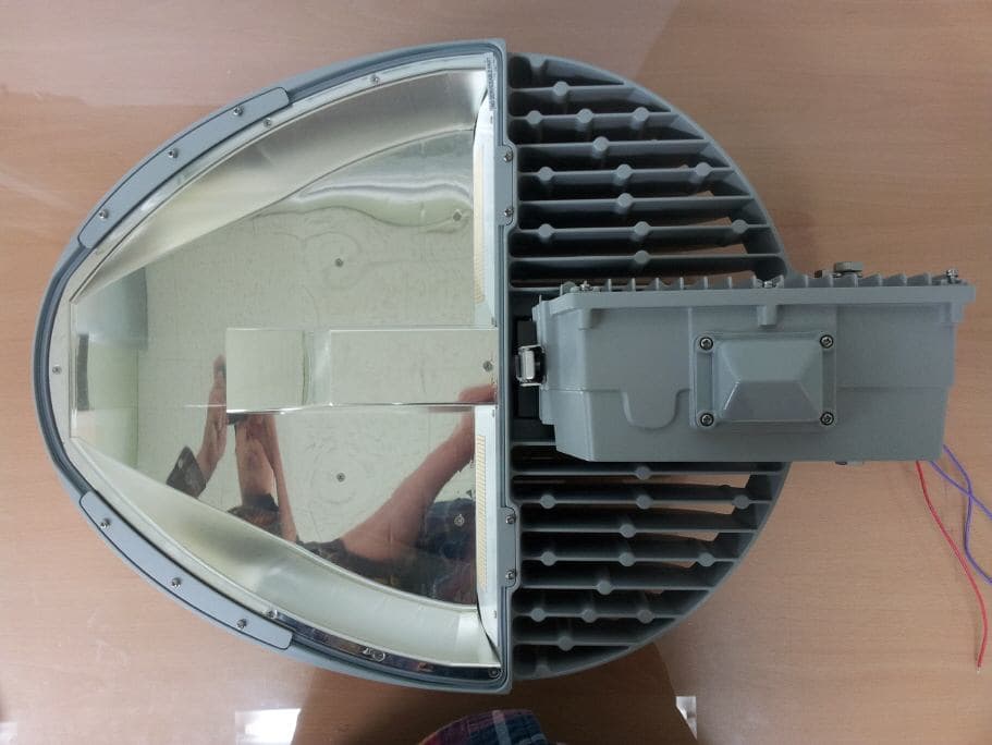
Click to zoom
Application Details
- Equipment Class
- DTS - Digital Transmission System
- Date of Grant
- Jan 15, 2013
- Application Purpose
- Original Equipment
- Date of Application
- Jan 15, 2013
- Equipment Note
- LED STREET LIGHT
- Frequency Range
- 2405.00000000 - 2480.00000000
- Company
- KMW INC.
- Country
- South Korea
Documents & Files
Document Text
Text extracted from the exhibit documents filed with the FCC. Open a document above to read the original.
Users Manual
HR R 85W | 110W | 150W Product Installation & Operation User Guide http://www.kmwgigatera.com Installation & Operation User Guide Roadway Lighting LED Serious injury might result if the following precautions are not followed. The user may be injured or there would be property damage if the instructions below are not followed. • The installation should be performed by certified workers under the relevant regulations of end user's country / region. • Never modify or disassemble LED lighting arbitrarily because it can cause serious accidents. • Never use any input power except the listed rated voltage. If not, it can cause serious accidents. • Before installation, shut off the power supply and verify it is de-powered using a measuring instrument. • The wiring should be insulated under end user's respective region's Electric Installations Standards. • Do not install in a wet environment. This symbol is intended to remind the user the presence of actions and operation that may cause danger. Please read instructions carefully and follow the instructions to avoid any danger. This symbol is intended to represent precautions that the user should follow to prevent danger. • Do not forcefully pull on AC/DC lines when wiring up the lighting. (It causes the wires to snap.) • Do not use this product for any purposes other than what’s specified. The manufacturer or sellers are not responsible for breakdowns or accidents caused by its improper use. • When connecting the wires, use proper connection terminals depending on the site of installation. Do not install in a wet environment. • Make sure to ground fixture by contacting it to metals around it to prevent damage by static. • The product may be damaged if static is not removed. • During the operation, be careful not to disconnect the wires. • Make sure the grounding is performed under Electricity Standards. • Using it for any voltage other than specified can cause failure or fire. • Do not use it in moist environment. • Be mindful of proper ventilation of product. • Improper installation or disassembly causes a deformation or breakdown of the product. • Consider proper protection devices, such as circuit breakers, fuses, switches, etc. for safety precautions. • Do not install in an enviroment with excessive vibration. • Do not handle product with contaminated hands or gloves. • In any event, do not store / install in a contaminated place. • Changes or modifications not expressly approved by the manufacturer could void the user's authority to operate the equipment. • This equipment has been tested and found to comply with the limits for a Class B digital device, pursuant to Part 15 of the FCC Rules. These limits are designed to provide reasonable protection against harmful interference in a residential installation. This equipment generates, uses and can radiate radio frequency energy and, if not installed and used in accordance with the instructions, may cause harmful interference to radio communications. However, there is no guarantee that interference will not occur in a particular installation. • If this equipment does cause harmful interference to radio or television reception, which can be determined by turning the equipment off and on, the user is encouraged to try to correct the interference by one or more of the following measures: - Reorient or relocate the receiving antenna. - Increase the separation between the equipment and receiver. - Connect the equipment into an outlet on a circuit different from that to which the receiver is connected. - Consult the dealer or an experienced radio/TV technician for help. WARNING CAUTION 『Safety Precautions Installation』 The information in this document is subject to change without notice Copyright 1991 ~ 2012 KMW, INC. All Rights Reserved © 3 Document Revision V0.61 2013.01.11 Pages R Street Light (HR) Installation & Operation User Guide Product Overview Product Features 1) Scope Overview This manual describes how to compose, install, and operate LED streetlamps. 2) LED Streetlight Apparatus A streetlight is a light that is installed on the side of least four-lane roads to improve traffic safety of vehicles and civilians as well as traffic efficiency. 3) Usage This is a traffic safety facility not only for expressways, streets, parking lots, and industrial facilities, but also for the safety on motorways or sidewalks. It is roughly divided into road lamps, sidewalk lamps, overbridge lamps, and high-mast lightings. The shape varies with the road feature and the beauty concept of your city to give you a lot of choices. The HR product lineup is 85W, 110W, 150W and all of them are proud of their high lamp efficiency over 100 lm/W. The lamp efficiencies are 8,500 lm, 11,000 lm, and 15,000 lm, respectively. The light distribution type is diversified. It supports Type II-S, Type II-M, Type III-S, Type-III-M to enable streetlamp installation in all environments. 1) Vertically Arranged LED Module Method HR adopted vertically arranged LED moduled unlike existing streetlamps. The vertically arranged LED mod- ules can help to minimize the heat generating from the LED and further guarantee long life of the device in the long run. 2) An Electronic Auto Switch Is Attached On top of a product is installed an electronic Auto Switch. When the intensity of illumination reaches a certain level, the lamp will be automatically turned off first and then it will be automatically turned off while it is not securing an illumination with sufficient intensity. In other words, it is a very convenient function to automati- cally turn on or off the lamp without operating the switch whenever necessary. 3) Converter (SMPS) Exchange without Tools HR adopted the Locking Lactch type to the locking device in the SMPS enclosure part to open or close the enclosure without any tool when you are exchanging the SMPS. In addition, the internal SMPS is fixed not by bolts but not sockets for more comfortable maintenance. 4) Silver Nanoreflecting …
Text truncated - open the document above for the full version.
Cover Letter(s)
Rev 11/20/07 183-6 Youngchun-ro, Dongtan-myun, Hwasung-si, Kyungki-do, Republic of Korea Tel No : +82-31-370-8621 Fax No : +82-31-370-0443 Federal Communications Commission Authorization and Evaluation Division Confidentiality Request regarding application for certification of FCC ID: ORI-HR110 Pursuant to Sections 0.457 and 0.459 of the Commission’s Rules, we hereby request confidential treatment of information accompanying this application as outlined below: Exhibit Type File Name Block Diagram Schematics Parts List Operational description Block Diagram (ORI-HR110).pdf Schematics (ORI-HR110).pdf Part List (ORI-HR110).pdf Operational Description (ORI-HR110).pdf The above materials contain trade secrets and proprietary information not customarily released to the public. The public disclosure of these materials may be harmful to the applicant and provide unjustified benefits to its competitors. The applicant understands that pursuant to Section 0.457 of the Rules, disclosure of this application and all accompanying documentation will not be made before the date of the Grant for this application. Pursuant to DA04-1705 June 15, 2004 of the Commission’s public notice, we also request temporary confidential treatment of information accompanying this application as outlined below: Exhibit Type File Name - - Sincerely, Sung Seok / Principal Research Engineer KMW INC.
External Photos
CTK Co., Ltd. 386-1, Ho-dong, Cheoin-gu, Yongin-si, Gyeonggi-do, 449-100, Korea Tel: +82-31-339-9970 Fax: +82-31-339-9855 www.e-ctk.com EUT External Photographs CTK Co., Ltd. 386-1, Ho-dong, Cheoin-gu, Yongin-si, Gyeonggi-do, 449-100, Korea Tel: +82-31-339-9970 Fax: +82-31-339-9855 www.e-ctk.com CTK Co., Ltd. 386-1, Ho-dong, Cheoin-gu, Yongin-si, Gyeonggi-do, 449-100, Korea Tel: +82-31-339-9970 Fax: +82-31-339-9855 www.e-ctk.com
ID Label/Location Info
CTK Co., Ltd. 386-1, Ho-dong, Cheoin-gu, Yongin-si, Gyeonggi-do, 449-100, Korea Tel: +82-31-339-9970 Fax: +82-31-339-9855 www.e-ctk.com Label and Location
Internal Photos
CTK Co., Ltd. 386-1, Ho-dong, Cheoin-gu, Yongin-si, Gyeonggi-do, 449-100, Korea Tel: +82-31-339-9970 Fax: +82-31-339-9855 www.e-ctk.com EUT Internal Photographs CTK Co., Ltd. 386-1, Ho-dong, Cheoin-gu, Yongin-si, Gyeonggi-do, 449-100, Korea Tel: +82-31-339-9970 Fax: +82-31-339-9855 www.e-ctk.com SMPS Board CTK Co., Ltd. 386-1, Ho-dong, Cheoin-gu, Yongin-si, Gyeonggi-do, 449-100, Korea Tel: +82-31-339-9970 Fax: +82-31-339-9855 www.e-ctk.com RF Board CTK Co., Ltd. 386-1, Ho-dong, Cheoin-gu, Yongin-si, Gyeonggi-do, 449-100, Korea Tel: +82-31-339-9970 Fax: +82-31-339-9855 www.e-ctk.com LED Board CTK Co., Ltd. 386-1, Ho-dong, Cheoin-gu, Yongin-si, Gyeonggi-do, 449-100, Korea Tel: +82-31-339-9970 Fax: +82-31-339-9855 www.e-ctk.com Antenna Board
Operational Description
5. Antenna Characteristic Horizontal Cartesian Vertical Cartesian
RF Exposure Info
CTK Co., Ltd. 386-1, Ho-dong, Cheoin-gu, Yongin-si, Gyeonggi-do, 449-100, Korea Tel: +82-31-339-9970 Fax: +82-31-339-9855 www.e-ctk.com Page 1 of 2 RF EXPOSURE EVALUATION Applicant : KMW INC. Applicant Address : 183-6 Youngchun-ro, Dongtan-myun, Hwasung- si, Kyungki-do, Republic of Korea FCC ID : ORI-HR110 Kind of Product : LED STREET LIGHT Equipment model name : HR110-A3S50xxx RF power : -0.86 dBm(0.820 mW) Peak Conducted Antenna type : Planar Inverted F antenna Antenna Gain : 2.13 dBi Frequency Range : 2405 MHz - 2480 MHz Number of channels : 16 CH CTK Co., Ltd. 386-1, Ho-dong, Cheoin-gu, Yongin-si, Gyeonggi-do, 449-100, Korea Tel: +82-31-339-9970 Fax: +82-31-339-9855 www.e-ctk.com Page 2 of 2 ** MPE Calculations ** The EUT will only be used with a separation of 20 centimeters or greater between the antenna and the body of the user. The MPE calculation for this exposure is shown below. The peak radiated output power (EIRP) is calculated as follows: EIRP = P + G Where, P = Power input to the antenna (mW) G = Power gain of the antenna (dBi) EIRP = -0.86 + 2.13 = 1.27 dBm The numeric gain(G) of the antenna with a gain specified in dB is determined by: G = Log -1 (dB antenna gain / 10) G = Log -1 (2.13 / 10) G = 1.63 Power density at the specific separation: S = PG/(4R 2 π) Where, S = Maximum power density (mW/cm 2 ) P = Power input to the antenna (mW) G = Numeric power gain of the antenna R = Distance to the center of the radiation of the antenna (20cm = limit for MPE) S = (1.34)/(4 * 20 2 * π) S =0.0003 mW/cm 2 The Maximum permissible exposure (MPE) for the general population is 1 mW/cm 2 . The power density at 20cm does not exceed the 1 mW/cm 2 limit. Estimated safe separation: R = √(PG / 4π) Where, P = Power input to the antenna (mW) G = Numeric power gain of the antenna R = Distance to the center of the radiation of the antenna (20cm = limit for MPE) R = √(1.34 / 4π) R = 0.3 cm
Schematics
New_job (Current screen) Scale=0.55 Thu Oct 18 19:28:18 2012 New_job (Current screen) Scale=0.55 Thu Oct 18 19:30:09 2012 CAM350 V 9.5 : Tue Jan 08 09:25:22 2013 - (Untitled) : TOP-SILK .pho CAM350 V 9.5 : Tue Jan 08 09:25:22 2013 - (Untitled) : BOT-SOLD MASK.ph
Test Report
CTK Co., Ltd. 386-1, Ho-dong, Cheoin-gu, Yongin-si, Gyeonggi-do, 449-100, Korea Tel: +82-31-339-9970 Fax: +82-31-339-9855 www.e-ctk.com Test Report No.: CTK-2013-00046 Date: January 14, 2013 Page 1 of 32 This Report shall not be reproduced except in full without the written approval of CTK Form No.: CTK-RF-EF-Part15 Subpart C(Rev.2) TEST REPORT According to : FCC 47CFR part 15 subpart C § 15.247 Test Report No. : CTK-2013-00046 Date of Issue : January 14, 2013 FCC ID : ORI-HR110 Model/Type No. : HR110-A3S50xxx Kind of Product : LED STREET LIGHT Applicant : KMW INC. Applicant Address : 183-6 Youngchun-ro, Dongtan-myun, Hwasung-si, Kyungki-do, Republic of Korea Manufacturer : KMW INC. Manufacturer Address : 183-6 Youngchun-ro, Dongtan-myun, Hwasung-si, Kyungki-do, Republic of Korea Contact Person : Sung Seok / Principal Research Engineer Telephone : +82–31-370-8621 Received Date : December 4, 2012 Test period : Start : December 17, 2012 End : January 8, 2013 Test Results : In Compliance Not in Compliance The test results presented in this report relate only to the object tested. Tested by Reviewed by Young-taek Lee Test Engineer Young-Joon, Park Technical Manager Date: January 14, 2013 Date: January 14, 2013 CTK Co., Ltd. 386-1, Ho-dong, Cheoin-gu, Yongin-si, Gyeonggi-do, 449-100, Korea Tel: +82-31-339-9970 Fax: +82-31-339-9855 www.e-ctk.com Test Report No.: CTK-2013-00046 Date: January 14, 2013 Page 2 of 32 This Report shall not be reproduced except in full without the written approval of CTK Form No.: CTK-RF-EF-Part15 Subpart C(Rev.2) REPORT REVISION HISTORY Date Revision Page No January 14, 2013 Issued (CTK-2013-00046) All This report shall not be reproduced except in full, without the written approval of CTK Co., Ltd. This document may be altered or revised by CTK Co., Ltd. personnel only, and shall be noted in the revision section of the document. Any alteration of this document not carried out by CTK Co., Ltd. will constitute fraud and shall nullify the document. CTK Co., Ltd. 386 -1, Ho -dong, Cheoin-gu, Yongin-si, Gyeonggi-do, 449-100, Korea Tel: +82-31 -339 -9970 Fax: +82-31 -339 -9855 www.e-ctk.com Test Report No.: CTK -2013-00046 Date: January 14, 2013 Page 3 of 32 This Report shall not be reproduced except in full without the written approval of CTK Form No.: CTK-RF-EF-Part15 Subpart C(Rev.2) TABLE OF CONTENTS REPORT REVISION HISTORY ........................................................................................... 2 1.0 General Product Description ................................................................................ 4 1.1 Tested Frequency ............................................................................................... 4 1.2 Model Differences .............................................................................................. 4 1.3 Device Modifications ........................................................................................... 5 1.4 Peripheral Devices ............................................................................................. 5 1.5 Calibration Details of Equipment Used for Measurement ......................................... 5 1.6 Test Facility ....................................................................................................... 5 1.7 Laboratory Accreditations and Listings .................................................................. 6 2.0 Summ ary of tests .............................................................................................. 7 2.1 Technical Characteristic Test ...................................................................................... 8 2.1.1 6dB Bandwidth ............................................................................................ 8 2.1.2 Maximum peak Conducted Output Power ...................................................... 11 2.1.3 Power Spectral Density ............................................................................... 13 2.1.4 Band - edge .............................................................................................. 17 2.1.5 Field Strength of Emissions ......................................................................... 22 2.1.6 AC Conducted Emissions ............................................................................. 29 APPENDIX A – Test Equipment Used For Tests ................................................................. 32 CTK Co., Ltd. 386-1, Ho-dong, Cheoin-gu, Yongin-si, Gyeonggi-do, 449-100, Korea Tel: +82-31-339-9970 Fax: +82-31-339-9855 www.e-ctk.com Test Report No.: CTK-2013-00046 Date: January 14, 2013 Page 4 of 32 This Report shall not be reproduced except in full without the written approval of CTK Form No.: CTK-RF-EF-Part15 Subpart C(Rev.2) 1.0 General Product Description Equipment model name : HR110-A3S50xxx Serial number : Prototype EUT condition : Pre-production, not damaged Antenna type : Planar Inverted F antenna Gain 2.13 dBi Frequency Range : 2405 MHz – 2480 MHz (DSSS) RF output power : -0.86 dBm Peak Conducted Number of channels : 16 Type of Modulation : OQPSK Rated Channel spacing : 5 MHz Power Source : AC 100 - 277 V 1.1 Tested Frequency LOW MID HIGH Frequency (MHz) 2405 2445 2480 1.2 Model Differences Not applicable CTK Co., Ltd. 386-1, Ho-dong, Cheoin-gu, Yongin-si, Gyeonggi-do, 449-100, Korea Tel: +82-31-339-9970 Fax: +82-31-339-9855 www.e-ctk.com Test Report No.: CTK-2013-00046 Date: January 14, 2013 Page 5 of 32 This Report shall not be reproduced except in full without the written approval of CTK Form No.: CTK-RF-EF-Part15 Subpart C(Rev.2) 1.3 Device Modifications The following modifications were necessary for compliance: Not applicable 1.4 Peripheral Devices 1.5 Calibration Details of Equipment Used for Measurement Test equipment and test accessories are calibrated on regular basis. The maximum time between calibrations is one year or what is recommended by the manufacturer, whichever is less. All test equipment calibrations are traceable…
Text truncated - open the document above for the full version.
Test Setup Photos
CTK Co., Ltd. 386-1, Ho-dong, Cheoin-gu, Yongin-si, Gyeonggi-do, 449-100, Korea Tel: +82-31-339-9970 Fax: +82-31-339-9855 www.e-ctk.com Test Setup Photographs and Configuration Conducted Voltage Emissions CTK Co., Ltd. 386-1, Ho-dong, Cheoin-gu, Yongin-si, Gyeonggi-do, 449-100, Korea Tel: +82-31-339-9970 Fax: +82-31-339-9855 www.e-ctk.com Radiated Electric Field Emissions CTK Co., Ltd. 386-1, Ho-dong, Cheoin-gu, Yongin-si, Gyeonggi-do, 449-100, Korea Tel: +82-31-339-9970 Fax: +82-31-339-9855 www.e-ctk.com CTK Co., Ltd. 386-1, Ho-dong, Cheoin-gu, Yongin-si, Gyeonggi-do, 449-100, Korea Tel: +82-31-339-9970 Fax: +82-31-339-9855 www.e-ctk.com
Contact Information
Applicant
Hyeon-seung Shin
Test Firm
CTK Co., Ltd.Young-Joon Park
Technical Specifications
| # | Rule Parts | Frequency Range | Power Output |
|---|---|---|---|
| 1 | 15C | 2.40 GHz - 2.48 GHz | 800.00 µW |
Other Applications from KMW INC.
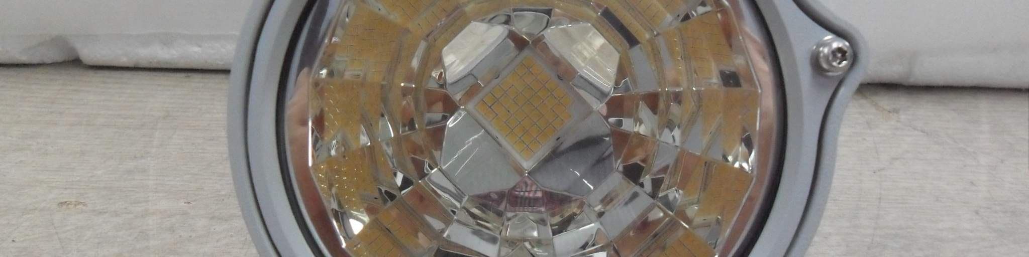
ORI-SPES2-080-E
Dec 22, 2014IT Converged Lighting
Equipment Class
DTS - Digital Transmission System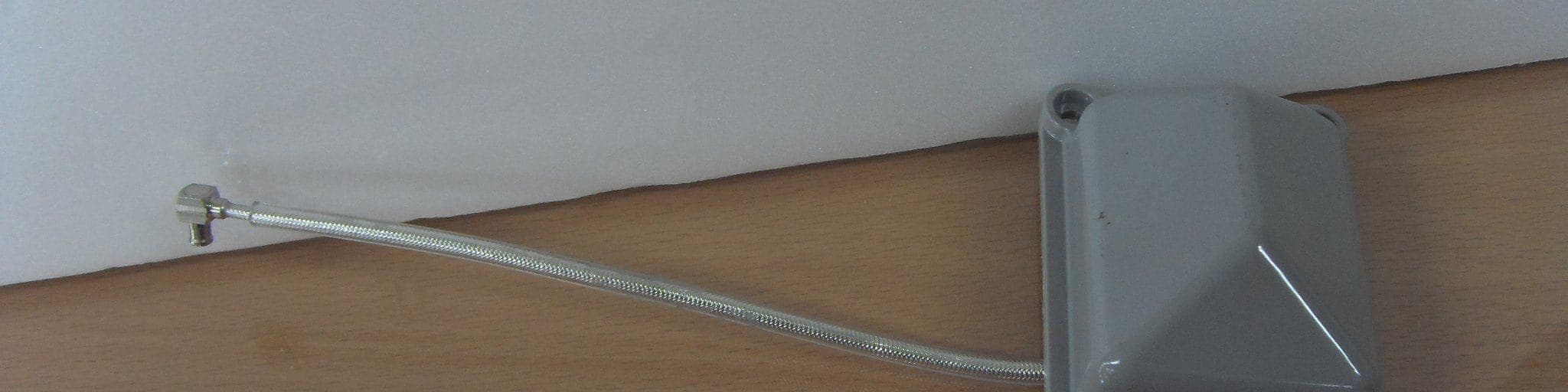
ORI-ZBNODE
Jan 01, 2014ZB Node
Equipment Class
DTS - Digital Transmission System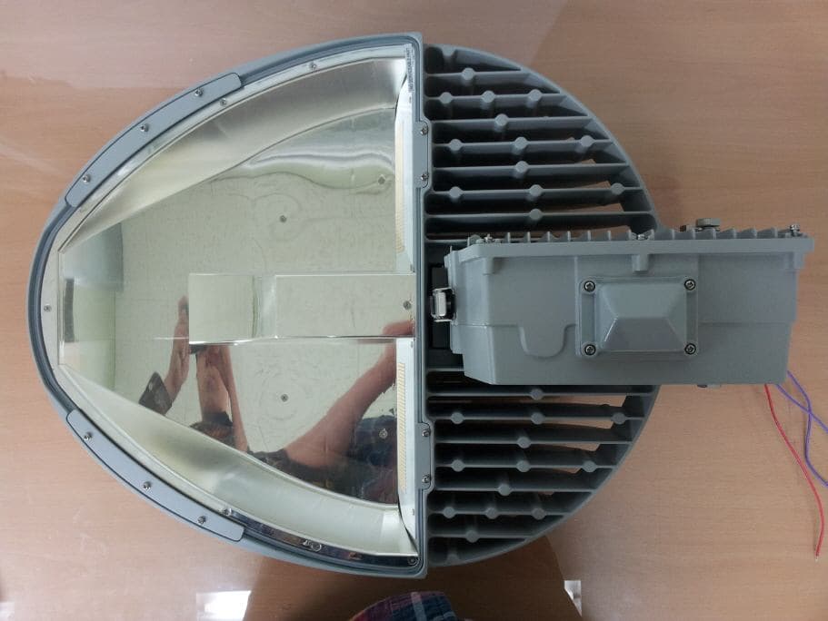
ORI-HR150
Jan 15, 2013LED STREET LIGHT
Equipment Class
DTS - Digital Transmission System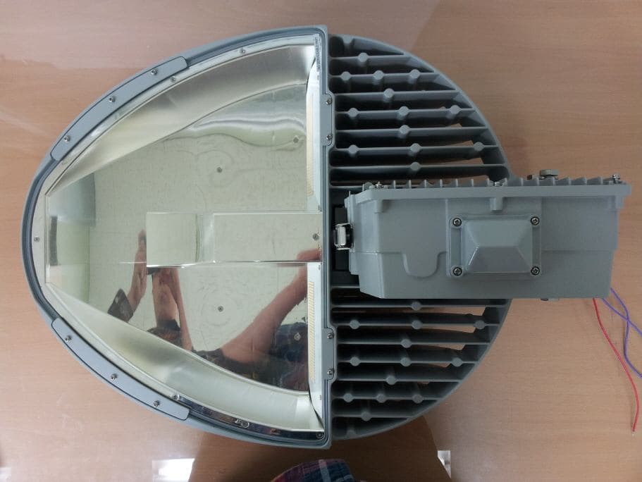
ORI-HR085
Jan 14, 2013LED STREET LIGHT
Equipment Class
DTS - Digital Transmission System