OT2MT3000BCar Alarm
Winstec Co., Ltd.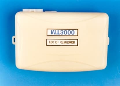
Click to zoom
Application Details
- Equipment Class
- DSR - Part 15 Remote Control/Security Device Transceiver
- Date of Grant
- Dec 07, 2000
- Application Purpose
- Original Equipment
- Date of Application
- Sep 20, 2000
- Equipment Note
- Car Alarm
- Frequency Range
- 434.79000000 - 434.79000000
- Company
- Winstec Co., Ltd.
- Country
- South Korea
Documents & Files
Document Text
Text extracted from the exhibit documents filed with the FCC. Open a document above to read the original.
Users Manual
Βραιν μανυαλ παγε οφ 101 MT3000 FCC ID : OT2MT3000B USER’S GUIDES RADIOPLUS CO., LTD. 42-13 wonmi-dong, Wonmi-ku, Puchon-City, Kyungki-Do, Korea FCC ID : OT2MT3000B This device complies with part 15 of the FCC rules. Operation subject to the following two conditions : (1) This device may not cause harmful interference, and (2) this device must accept any interference received, including interference that may cause undesired operation. Caution : any changes or modifications in construction of this device which are not expressly approved by the party responsible for compliance could void the user's authority to operate the equipment. Βραιν μανυαλ παγε οφ 102 TABLE OF CONTENTS 1. PRODUCTION’S DISTINCTION--------------------Brain manual page 3 of 11 2. EACH ICON SIMPLE EXPLANATION-------------- Brain manual page 4 of 11 3.SWITCH GUIDESPOT-------------------------- Brain manual page 5 of 11 4.FUNCTION KEY EXPLANATIONS----------------- Brain manual page 6 of 11 4-1.LOCK/UNLOCK------------------------- Brain manual page 6 of 11 4-2.REMOTE START ENGINE ON and OFF.------ Brain manual page 6 of 11 4-3.FIND--------------------------------- Brain manual page 6 of 11 4-4.PANIC ON/OFF------------------------- Brain manual page 6 of 11 4-5.AUX 1/2 OUTPUT POWER---------------- Brain manual page 6 of 11 4-6.TRUNK OPEN-------------------------- Brain manual page 6 of 11 5.MENU EXPLANATION-------------------------- Brain manual page 7 of 11 5-1.VEHICLE SIREN SET –UP. (ICON PICTURE)--- Brain manual page 7 of 11 5-2.COLD STARTS SETTING-UP.-------------- Brain manual page 7 of 11 5-3.RESERVE START ENGINE TIME------------ Brain manual page 7 of 11 5-4.VALET SET-UPS------------------------ Brain manual page 7 of 11 5-5.AUTO LOCK/UNLOCK-------------------- Brain manual page 7 of 11 5-6.ENGINE WARM-UP TIME MODES----------- Brain manual page 7 of 11 5-7.REMOTE MORNING CALL MODES----------- Brain manual page 8 of 11 5-8.REMOTER FOR SETTING TIME.------------- Brain manual page 8 of 11 5-9.REMOTOR POWER –OFF------------------ Brain manual page 8 of 11 6.SORTS OF ALARM RECEIVER-------------------- Brain manual page 9 of 11 6-1.LIGHT IMPACT RECEIVERS--------------- Brain manual page 9 of 11 6-2.HEAVY IMPACT RECEIVER---------------- Brain manual page 9 of 11 6-3.DOOR OPEN SENSORS------------------- Brain manual page 9 of 11 6-4.ENGINE STARTING MODES--------------- Brain manual page 9 of 11 6-5.HOOD OPEN PERCEPTIONS--------------- Brain manual page 9 of 11 6-6.TRUNK OPEN PERCEPTIONS.-------------- Brain manual page 9 of 11 6-7. VEHICLE LOW BATTERYALARM FUNCTION- Brain manual page 9 of 11 6-8.ACTION ERRORS NOTIFY ALARM FUNCTION- Brain manual page 9 of 11 7.IN THE CASE OF MANUAL TRANSMISSION VEHICLE- Brain manual page 11 of 11 1 . PRODUCTION’S DISTINCTION Thank you very much for purchasing RADIOPLUS MILLENNNIUM MAX. This production is made more convenient and satisfy vehicle security user with the most advanced communication protocol and battery saving time. Please, be aware of this direction book before using the production. -Convenience of use Taking advantage of ICON to all functions makes the production handled any function easily. Therefore, allows use this even at first can handle with any differences. -Dialogue form carriage Allows LCD and buzzer of remoter indicate all answers from orders. User doesn’t have feelings of anxieties. -Full setting method User can set up so far as detail time thorough cold start, reserve start, warm-up etc. -Easy to judge alarm When alarm situation takes place, all movements are embodied as if real car situation. User grasps the situation easily. Each situation’s buzzer tone is different to distinguish Βραιν μανυαλ παγε οφ 103 with ease. -Safety functions and loading All functions are preserved that used by user even power-off .No need to set mode again after exchanging batteries. Βραιν μανυαλ παγε οφ 104 2. EACH ICON SIMPLE EXPLANATION 1.ANTENNA 12.REMOTE CALL 2.HORN 13.REMOTOR MORNING CALL 3.VALET 14.REMOTOR TIME SET 4.AUTO LOCK/UNLOCK 15. REMOTOR POWER OFF 5.COLD START 16.PARKING/DRIVING TIME 6.RESERVE STAR 17.IMPACT (HIGH/LOW) 7.WARM-UP TIME 18.HOOD OPEN 8.CLOCK 19.DOOR OPEN 9.VEHICLE LOW BATTERY 20.TRUNK OPEN 10.REMOTOR LOW BATTERY 21. ENGINE START 11.RUNNING ERROR 22.LOCK/UNLOCK 3.SWITCH GUIDESPOT Βραιν μανυαλ παγε οφ 105 1.STARTING ENGINE SWITCH AND MENU -Press button to control engine start shortly. -Press button long enough to conclude after choosing function of ICON blinking currently or enter the menu mode to correct detail contents. 2.LOCK/UNLOCK PANIC MODE -Press shortly for lock/unlock operation -Press long for panic on/off operation. -In menu mode, setting ICON becomes movable to right and left. In the detail set-up mode, data adds +1 gradually. 3.AUX. 1/2 OUTPUT SWICH -Press shortly for AUX.1 operation. -Press long for AUX.2 operation. -In menu mode, setting ICON becomes movable to right and left. In the detail set-up mode, data adds –1 gradually. ICON SHORT LONG Lock / Unlock Panic Find Trunk Aux1 Aux2 Menu mode Engine start 4.FUNCTION KEY EXPLANATIONS . 4-1.LOCK/UNLOCK Make car into the opposite state unlocked or locked in turn. You can recognize it through LCD. Lock situation accompany alarm mode, unlock goes with non-alarm. Light react once and siren twice after normal performance. 4-2.REMOTE START ENGINE ON and OFF. Control car remotely. Warming up engine time is settled by warm-up time as memorized. When cold-start, reserve-start, remote-start are operated just press button to stop them. Lights and siren react 4times after normal performance 4-3.FIND To know where car is located and current car situation. Lights and siren react 3times after normal situation. 4-4.PANIC ON/OFF Emergency case is notified by blinking of lights and siren. Press twice for termination. Standard action time is 30 sec.; you can change time from 1sec. to 99 sec. With installer. 4-5.AUX 1/2 OUTPUT POWER. Use to control heater air conditioner, sunroof, audio. It is possible to connect selected…
Text truncated - open the document above for the full version.
Users Manual
Brain manual page of 11 1 MT3000 FCC ID : OT2MT3000B USER’S GUIDES RADIOPLUS CO., LTD. 42-13 wonmi-dong, Wonmi-ku, Puchon-City, Kyungki-Do, Korea FCC ID : OT2MT3000B This device complies with part 15 of the FCC rules. Operation subject to the following two conditions : (1) This device may not cause harmful interference, and (2) this device must accept any interference received, including interference that may cause undesired operation. Caution : any changes or modifications in construction of this device which are not expressly approved by the party responsible for compliance could void the user's authority to operate the equipment. Brain manual page of 11 2 TABLE OF CONTENTS 1.PRODUCTION’S DISTINCTION--------------------Brain manual page 3 of 11 2. EACH ICON SIMPLE EXPLANATION-------------- Brain manual page 4 of 11 3.SWITCH GUIDESPOT-------------------------- Brain manual page 5 of 11 4.FUNCTION KEY EXPLANATIONS----------------- Brain manual page 6 of 11 4-1.LOCK/UNLOCK------------------------- Brain manual page 6 of 11 4-2.REMOTE START ENGINE ON and OFF.------ Brain manual page 6 of 11 4-3.FIND--------------------------------- Brain manual page 6 of 11 4-4.PANIC ON/OFF------------------------- Brain manual page 6 of 11 4-5.AUX 1/2 OUTPUT POWER---------------- Brain manual page 6 of 11 4-6.TRUNK OPEN-------------------------- Brain manual page 6 of 11 5.MENU EXPLANATION-------------------------- Brain manual page 7 of 11 5-1.VEHICLE SIREN SET –UP. (ICON PICTURE)--- Brain manual page 7 of 11 5-2.COLD STARTS SETTING-UP.-------------- Brain manual page 7 of 11 5-3.RESERVE START ENGINE TIME------------ Brain manual page 7 of 11 5-4.VALET SET-UPS------------------------ Brain manual page 7 of 11 5-5.AUTO LOCK/UNLOCK-------------------- Brain manual page 7 of 11 5-6.ENGINE WARM-UP TIME MODES----------- Brain manual page 7 of 11 5-7.REMOTE MORNING CALL MODES----------- Brain manual page 8 of 11 5-8.REMOTER FOR SETTING TIME.-------------Brain manual page 8 of 11 5-9.REMOTOR POWER –OFF------------------ Brain manual page 8 of 11 6.SORTS OF ALARM RECEIVER-------------------- Brain manual page 9 of 11 6-1.LIGHT IMPACT RECEIVERS--------------- Brain manual page 9 of 11 6-2.HEAVY IMPACT RECEIVER---------------- Brain manual page 9 of 11 6-3.DOOR OPEN SENSORS------------------- Brain manual page 9 of 11 6-4.ENGINE STARTING MODES--------------- Brain manual page 9 of 11 6-5.HOOD OPEN PERCEPTIONS--------------- Brain manual page 9 of 11 6-6.TRUNK OPEN PERCEPTIONS.-------------- Brain manual page 9 of 11 6-7. VEHICLE LOW BATTERYALARM FUNCTION- Brain manual page 9 of 11 6-8.ACTION ERRORS NOTIFY ALARM FUNCTION- Brain manual page 9 of 11 7.IN THE CASE OF MANUAL TRANSMISSION VEHICLE- Brain manual page 11 of 11 8.BRAIN OPERATE DESCRIPTION------------------ Brain manual page 11 of 11 1 . PRODUCTION’S DISTINCTION Thank you very much for purchasing RADIOPLUS MILLENNNIUM MAX. This production is made more convenient and satisfy vehicle security user with the most advanced communication protocol and battery saving time. Please, be aware of this direction book before using the production. -Convenience of use Taking advantage of ICON to all functions makes the production handled any function easily. Therefore, allows use this even at first can handle with any differences. -Dialogue form carriage Allows LCD and buzzer of remoter indicate all answers from orders. User doesn’t have feelings of anxieties. -Full setting method User can set up so far as detail time thorough cold start, reserve start, warm-up etc. -Easy to judge alarm When alarm situation takes place, all movements are embodied as if real car situation. User grasps the situation easily. Each situation’s buzzer tone is different to distinguish Brain manual page of 11 3 with ease. -Safety functions and loading All functions are preserved that used by user even power-off .No need to set mode again after exchanging batteries. Brain manual page of 11 4 2. EACH ICON SIMPLE EXPLANATION 1.ANTENNA 12.REMOTE CALL 2.HORN 13.REMOTOR MORNING CALL 3.VALET 14.REMOTOR TIME SET 4.AUTO LOCK/UNLOCK 15. REMOTOR POWER OFF 5.COLD START 16.PARKING/DRIVING TIME 6.RESERVE STAR 17.IMPACT (HIGH/LOW) 7.WARM-UP TIME 18.HOOD OPEN 8.CLOCK 19.DOOR OPEN 9.VEHICLE LOW BATTERY 20.TRUNK OPEN 10.REMOTOR LOW BATTERY 21. ENGINE START 11.RUNNING ERROR 22.LOCK/UNLOCK 3.SWITCH GUIDESPOT Brain manual page of 11 5 1.STARTING ENGINE SWITCH AND MENU -Press button to control engine start shortly. -Press button long enough to conclude after choosing function of ICON blinking currently or enter the menu mode to correct detail contents. 2.LOCK/UNLOCK PANIC MODE -Press shortly for lock/unlock operation -Press long for panic on/off operation. -In menu mode, setting ICON becomes movable to right and left. In the detail set-up mode, data adds +1 gradually. 3.AUX. 1/2 OUTPUT SWICH -Press shortly for AUX.1 operation. -Press long for AUX.2 operation. -In menu mode, setting ICON becomes movable to right and left. In the detail set-up mode, data adds –1 gradually. ICON SHORT LONG Lock / Unlock Panic Find Trunk Aux1 Aux2 Menu mode Engine start 4.FUNCTION KEY EXPLANATIONS . 4-1.LOCK/UNLOCK Make car into the opposite state unlocked or locked in turn. You can recognize it through LCD. Lock situation accompany alarm mode, unlock goes with non-alarm. Light react once and siren twice after normal performance. 4-2.REMOTE START ENGINE ON and OFF. Control car remotely. Warming up engine time is settled by warm-up time as memorized. When cold-start, reserve-start, remote-start are operated just press button to stop them. Lights and siren react 4times after normal performance 4-3.FIND To know where car is located and current car situation. Lights and siren react 3times after normal situation. 4-4.PANIC ON/OFF Emergency case is notified by blinking of lights and siren. Press twice for termination. Standard action time is 30 sec.; you can change time from 1sec. to 99 sec. With installer. 4-5.AUX 1/2 OUTPUT POWER. Use to contro…
Text truncated - open the document above for the full version.
Block Diagram
Antenna(Helical Type) RX/TX Common use RX/TX Switching RF amplify Band pass filter Rf High filter 2st amplify 1st mixxer and Band pass filter middle frequncy Band pass amplify filter 1st amplify 1st middle RF buffer frequncy filter 2st Local Band pass oscillation 2st mixxer filter FM detection and Local audio frequncy filter oscillation Modulation RX data Input RF Power TX data output Micro-Controller switching switching (GMS97C52) Real time clock Regulator(5V) Siren out, LED out, Trunk release, Starter kill Battery(12V) Door trigger, Shock sensor, Hood trigger, Ign(Key) tregger
External Photos
External Photos Βραιν – τοπ Βραιν − φροντ Βραιν − βοττομ
ID Label/Location Info
ID Label
Internal Photos
Internal Photos Brain PCB – top Brain PCB – bottom
Operational Description
---- RF block diagram ---- a1 a2 a3 a4 (Tx data )Modulation Local RF buffer RF amplify a5 oscillation (413.39 MHz) Antenna CPU (TMP87CH21DF) b3 b6 RX/TX 2ST oscilation switching (20.945MHz) b1 b2 b4 b5 RX dat aFM data 2ST mixer 1ST mixer RF amplify detection <Picture 1> - A basic carrier frequency consists of a1, a2, a3 (on picture 1). - Receiver : super heterodyne recever - Modulatin type : FM FSK(frequncy shift keying) - Remote transmitting frequncy : 413.39MHz - Remote recive local oscillation frequncy : 434.79MHz - Brain transmitting frequncy : 434.79MHz - Brain recive local oscillation frequncy : 413.39MHz 1. Remote control 1.1 Transmission Modulation signal is occurred at CPU pin no 15. Modulation is formed at a1 (VD1), a2 (Q6). a3 (Q7) creates frequency 413.39MHz. Makes 413.39MHz signal transmit to the brain through a4 (Q8, Q9)-b6 (D4, D2)- a5 1.2 Receiver A carrier frequency (434.79MHz) amplifies at b5 (Q1, Q2) pass through a5 (antenna ) B4 (Q3) receives signals of a3 (Q7), b5 and makes 1st IF (21.4MHz) to send b2 (U1) B2 (U1) mixes with 2nd local oscillation frequency (20.945MHz) of b3 (X2) and make 455Khz demodulates FM at b1 (X3) and detects data signal. Sends detected data signals to CPU no 19. 2. Brain 2.1 Transmission Modulation signal is occurred at CPU pin no 23. Modulation is formed at a1 (D2), a2 (Q3). a3 (Q4) creates frequency 434.79MHz. Makes 434.79MHz signal transmit to the remote control through a4 (Q5, Q6)-b6 (D4, 2.2 Receiver A carrier frequency (413.39MHz) amplifies at b5 (Q7, Q8) pass through a5 (antenna ) B4 (Q9) receives signals of a3 (Q4), b5 and makes 1st IF (21.4MHz) to send b2 (IC1 B2 (IC1) mixes with 2nd local oscillation frequency (20.945MHz) of b3 (X102) and m 455Khz demodulates FM at b1 (X103) and detects data signal.
Operational Description
BRAIN TRANSMITTER DESCRIPTION 1.DATA OUT 1) IN CASE OF SENDING DATA TO REMOTOR (1) EVENT HAPPPEN Tachometer, generator input Brake shut dow n input Rear light input Wait to start input Door trigger input (refer to brain wiring diagram) Trunk pin switch input Hood pin switch input Soft trigger Hard trigger When one of these events happen, event data is sent to the CPU IC1 (GMS 90C51). Then, IC1(GMS 90C51) 23rd pin will send out proper data. At the same time, power is transmitted to trans mi tter part. (Refer to control part circuit diagram at RTS BRAIN) (2) Data from CPU is modulated at D2(1SV154)-refer to MT Brain RF part). Modulated data is transmitted to L1, crystal X101. (3) Basic frequency 48.1988Mhz crystal becomes triple to 144.5966 at oscillation circuit (consist of Q3, L3, C7, C8, L2). This frequency 144.5966Mhz become triple again to carrier frequency 433.79Mhz at circuit (Q4, L5, C14). (4) 433.79Mhz frequency passes by buffer Q5,C7,C23 and amp Q6,L8,C25 then transmitted to antenna for release to outside. 2) IN CASE OF RECEIVING DATA FROM REMOTOR A certain data (ex. door unlock) from remoter will be fulfilled and door unlock data will pass through above (2) ~ (4) then send to remoter
Operational Description
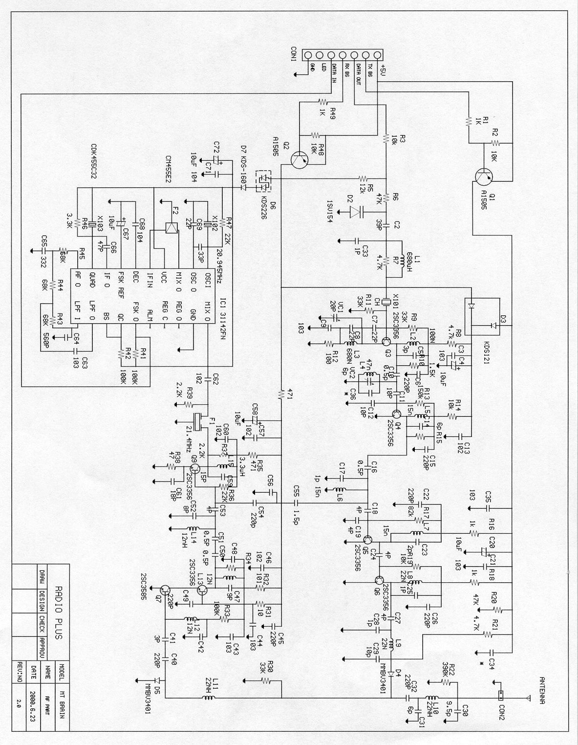
RF Circuit description of Brain The signal from MPV PIN #23 (location # IC1) is modulated by Variable – Capacitance Diode (location # D2). The modulated signal is transferred to crystal (location # X 101) through C2, L1 and R7 Crystal (location # X101) as the fundamental frequency is oscillated and formed as 48.31MHZ. The frequency of 48.31MHZ is multiplied by the components such as Q3, L3, C7, C8, C9, R12 and VC1.The multiplied frequency is filtered and formed for the frequency of 434.79MHZ by Q4, L5 and C14. The frequency of 434.79MHZ is buffered through the components of Q5, C7, C23 and amplified through the components of Q6, L8, C25 and then transferred to Antenna . Brain operation description ! The signal occur only under two kinds of the circumstances as stated below 1) In case of receiving a signal from remote On receiving an order from Remote, Brain operates on the order received and Brain operation is finished after transmitting the result of operation to Remote. That is to say, Brain is not operated until receiving a signal from Remote. Cf. The kind of the order from remote are such as Door Lock/Unlock Engine start, etc. 2) In case of event happen to vehicle in arm When event occur, the brain transmit the event signal to Remote and then Brain operation is finished. For example, in case of door open, Brain operates siren and transmit the signal of door opened to remote once. Cf. The kind of event signal are such as Door open, Hood open, Trunk Open, Engine Start, Rear light.
Operational Description
BIT STREAM : ' PREAMBLE ID-1 EVENT DATA JOB ID-2 CECHK-SUMFFh FEh 11h 01h 00h 40h 11H 41h12345678123456781234567812345678123456781234567812345678123456781111111111111110000100010000000100000000010000000001000101000001
Schematics
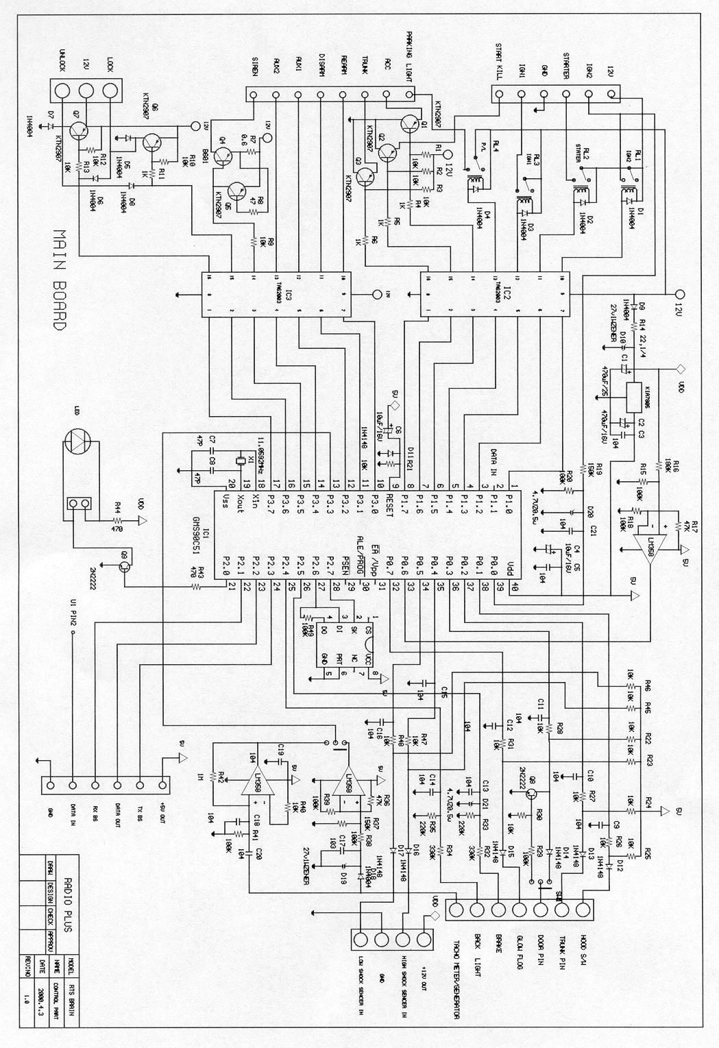
Βραιν λογιχ χιρχυιτ Βραιν ΡΦ χιρχυιτ
Test Report
KTL Korea Testing Laboratory Page 1 of 14 TEST REPORT This test report only responds to the tested sample and shall not be reproduced except in full without written approval of the Korea Testing Laboratory. Tested and reported by Reviewed by Jeong-Min Kim , Senior Engineer Seok-Jin Kim ,EMC Team Leader KOREA TESTING LABORATORY FG101-01-02-00 222-13, Guro-Dong Guro-Gu Seoul Korea 152-053 http://www.ktl.re.kr Ref. Report No. 00-341-043-01 Test item( s) ; Re mote Cont rol/Se curity Device Transceiver (Remote Car Alarm (Brain)) Model/type ref. ; MT3000B Manufacturer ; Radioplus Co., Ltd. Additional information ; -Re quire d Aut ho riz atio n : Ce rtificatio n -FCC ID: OT2MT3000B - Note : Te st re port(Ve rificatio n) of Re ce ive r po rtio n of t his unit is iss ue d o n Re f. Re port No. 00-341-043-02. Name and address of the applicant Radioplus Co., Ltd. 42-13, Wonmi-Dong, Wonmi-Ku, Puchon-Shi Kyungki-Do, Korea 420-110 Standard / Test regulation FCC Part 15, Subpart C Test result Pass Incoming date : August 25, 2000 Test date : September 19, 2000 Issue date : September 21, 2000 Ref. Report No. 00-341-043-01 2 Page of 14 TABLE O F CONTENTS I. GENERAL INFORMATION ............................................................................................................ 3 1. Grantee’s Name and Mailing Address 2. Manufacturer's Name and Mailing Address 3. Equipment Descriptions 4. Rules and Regulations 5. Measuring Procedure 6. Date of Measurement α. GENERAL REQUIREMENTS OF THE EUT .................................................................4 1. Labelling Requirement (Section 15.19) 2. Information to User (Sections 15.21) 3. Special Accessories (Section 15.27) 4. Compliant Conditions (Section 15.231) β. RADIATED EMISSION MEASUREMENT (Section 15.231) .......................................................6-12 1. Test Procedure 2. Photograph for the worst case configuration 3. Sample Calculation 4. Measurement Data 5. Reference Data χ. OCCUPIED BANDWIDTH MEASUREMENT (Section 15.231).................................................13 δ. TEST EQUIPMENTS USED FOR MEASUREMENT..................................................................14 Ref. Report No. 00-341-043-01 3 Page of 14 . GENERAL INFORMATION 1. Grantee’s Name and : Radioplus Co., Ltd. Mailing Address 42-13, Wonmi-Dong, Wonmi-Ku, Puchon-Shi, Kyungki-Do, Korea 420-110 2. Manufacturer's Name and: Radioplus Co., Ltd. Mailing Address 42-13, Wonmi-Dong, Wonmi-Ku, Puchon-Shi, Kyungki-Do, Korea 420-110 3. Equipment Descriptions 3.1 Operating Frequency : 434.79 MHz 3.2 Type of Emission : FM Pulse Code Signal 3.3 Used Oscillator: 72.46 MHz 3.4 Power Supply: DC 12V(Car Battery) 4. Rules and Regulations: FCC Part 15, Subpart C 5. Measuring Procedure: ANSI C63.4-1992 6. Date of Measurement 6.1 Line Conducted: Not Applicable 6.2 Radiated Emission : September 19, 2000 Ref. Report No. 00-341-043-01 4 Page of 14 . GENERAL REQUIREMENTS O F THE EUT 1. Labelling Requirement (Section 15.19) This device complies with Part 15 of the FCC Rules. Operation is subject to the following two conditions: (1) this device may not cause harmful interface, and (2) this device must accept any interference received, including interference that may cause undesired operation. 1.1 Location of Label : Bottom side of EUT 1.2 How Applied : By ink-printing on adhesive label 2. Information to User (Section 15.21) The following or similar statements were provided in the manual for user instruction. Please refer page 1 of the attached manual for details. CA UT ION : A ny c ha nges or modifications i n cons truc tion o f this device w hich are not e xpressly approved by the party responsible for compliance could void the user's authority to operate the equipment. 3. Special Accessories (Section 15.27) 3.1 Were the special Accessories provided? [ ] yes, [ x ] no 3.2 If yes, details for the special accessories are as follows : 3.3 If yes, were the appropriate instructions provided on the first page of the text concerned with the device? [ ] yes, [ ] no 3.4 Are these accessories provided of the type which can be readily obtained from multiple retail outlets ? [ ] yes, [ ] no And therefore does the manual specify what additional components or accessories are required to used in order to comply with the Rules? [ ] yes, [ ] no Ref. Report No. 00-341-043-01 5 Page of 14 4. Compliant Conditions (Section 15.231) 4.1 Was the EUT used for continuous transmissions, such as voice or video, and data transmission ? [ ] yes, [ x ] no 4.2 Was the EUT manually operated ? [ x ] yes, [ ] no If yes, did the EUT employ a switch that would automatically deactivate the transmitter within not more than 5 seconds of being released ? [ x ] yes, [ ] no 4.3 Was the EUT automatically activated ? [ ] yes, [ x ] no If yes, did the EUT cease transmission within 5 seconds after deactivation ? [ ] yes, [ ] no 4.4 Was the EUT used for periodic transmissions at regular predetermined intervals ? [ ] yes, [ x ] no Ref. Report No. 00-341-043-01 6 Page of 14 . RADIATED EMISSION MEASUREMENT (Section 15.231) 1. Test Procedure 1.1 Preliminary Testing for Reference Preliminary testing was performed in a KTL absorber-lined room to determine the emission characteristics of the EUT. The EUT was placed on the wooden table which has dimensions of 0.8 meters in height, 1 meter in length and 1.5 meters in width. Receiving antenna (Biconical antenna : 30 to 300MHz, Log-periodic antenna : 200 to 1000MHz or Horn Antenna : 1 to 18GHz) was placed at the distance of 1 meter from the EUT. An attempt was made to maximize the emission level with the various configurations of the EUT. The position of the EUT was horizontally or vertically changed to find the worst case configuration. Emissions level from the EUT with various configurations were examined on a spectrum analyzer connected with a RF amplifier and graphed by a plotter. 1.2 Final Radiated Emission Test at a Absorber-Lined Room The final measurement of radiated field streng…
Text truncated - open the document above for the full version.
Test Report
KTL Korea Testing Laboratory Page 1 of 14 TEST REPORT This test report only responds to the tested sample and shall not be reproduced except in full without written approval of the Korea Testing Laboratory. Tested and reported by Reviewed by Jeong-Min Kim , Senior Engineer Seok-Jin Kim ,EMC Team Leader KOREA TESTING LABORATORY FG101-01-02-00 222-13, Guro-Dong Guro-Gu Seoul Korea 152-053 http://www.ktl.re.kr Ref. Report No. 00-341-043-01 Test item( s) ; Re mote Cont rol/Se curity Device Transceiver (Remote Car Alarm (Brain)) Model/type ref. ; MT3000B Manufacturer ; Radioplus Co., Ltd. Additional information ; -Re quire d Aut ho riz atio n : Ce rtificatio n -FCC ID: OT2MT3000B - Note : Te st re port(Ve rificatio n) of Re ce ive r po rtio n of t his unit is iss ue d o n Re f. Re port No. 00-341-043-02. Name and address of the applicant Radioplus Co., Ltd. 42-13, Wonmi-Dong, Wonmi-Ku, Puchon-Shi Kyungki-Do, Korea 420-110 Standard / Test regulation FCC Part 15, Subpart C Test result Pass Incoming date : August 25, 2000 Test date : September 19, 2000 Issue date : September 21, 2000 Ref. Report No. 00-341-043-01 2 Page of 14 TABLE O F CONTENTS I. GENERAL INFORMATION ............................................................................................................ 3 1. Grantee’s Name and Mailing Address 2. Manufacturer's Name and Mailing Address 3. Equipment Descriptions 4. Rules and Regulations 5. Measuring Procedure 6. Date of Measurement α. GENERAL REQUIREMENTS OF THE EUT .................................................................4 1. Labelling Requirement (Section 15.19) 2. Information to User (Sections 15.21) 3. Special Accessories (Section 15.27) 4. Compliant Conditions (Section 15.231) β. RADIATED EMISSION MEASUREMENT (Section 15.231) .......................................................6-12 1. Test Procedure 2. Photograph for the worst case configuration 3. Sample Calculation 4. Measurement Data 5. Reference Data χ. OCCUPIED BANDWIDTH MEASUREMENT (Section 15.231).................................................13 δ. TEST EQUIPMENTS USED FOR MEASUREMENT..................................................................14 Ref. Report No. 00-341-043-01 3 Page of 14 . GENERAL INFORMATION 1. Grantee’s Name and : Radioplus Co., Ltd. Mailing Address 42-13, Wonmi-Dong, Wonmi-Ku, Puchon-Shi, Kyungki-Do, Korea 420-110 2. Manufacturer's Name and: Radioplus Co., Ltd. Mailing Address 42-13, Wonmi-Dong, Wonmi-Ku, Puchon-Shi, Kyungki-Do, Korea 420-110 3. Equipment Descriptions 3.1 Operating Frequency : 434.79 MHz 3.2 Type of Emission : FM Pulse Code Signal 3.3 Used Oscillator: 48.1988 MHz 3.4 Power Supply: DC 12V(Car Battery) 4. Rules and Regulations: FCC Part 15, Subpart C 5. Measuring Procedure: ANSI C63.4-1992 6. Date of Measurement 6.1 Line Conducted: Not Applicable 6.2 Radiated Emission : September 19, 2000 Ref. Report No. 00-341-043-01 4 Page of 14 . GENERAL REQUIREMENTS O F THE EUT 1. Labelling Requirement (Section 15.19) This device complies with Part 15 of the FCC Rules. Operation is subject to the following two conditions: (1) this device may not cause harmful interface, and (2) this device must accept any interference received, including interference that may cause undesired operation. 1.1 Location of Label : Bottom side of EUT 1.2 How Applied : By ink-printing on adhesive label 2. Information to User (Section 15.21) The following or similar statements were provided in the manual for user instruction. Please refer page 1 of the attached manual for details. CA UT ION : A ny c ha nges or modifications i n cons truc tion o f this device w hich are not e xpressly approved by the party responsible for compliance could void the user's authority to operate the equipment. 3. Special Accessories (Section 15.27) 3.1 Were the special Accessories provided? [ ] yes, [ x ] no 3.2 If yes, details for the special accessories are as follows : 3.3 If yes, were the appropriate instructions provided on the first page of the text concerned with the device? [ ] yes, [ ] no 3.4 Are these accessories provided of the type which can be readily obtained from multiple retail outlets ? [ ] yes, [ ] no And therefore does the manual specify what additional components or accessories are required to used in order to comply with the Rules? [ ] yes, [ ] no Ref. Report No. 00-341-043-01 5 Page of 14 4. Compliant Conditions (Section 15.231) 4.1 Was the EUT used for continuous transmissions, such as voice or video, and data transmission ? [ ] yes, [ x ] no 4.2 Was the EUT manually operated ? [ ] yes, [ x ] no If yes, did the EUT employ a switch that would automatically deactivate the transmitter within not more than 5 seconds of being released ? [ ] yes, [ ] no 4.3 Was the EUT automatically activated ? [ x ] yes, [ ] no If yes, did the EUT cease transmission within 5 seconds after activation ? [ x ] yes, [ ] no 4.4 Was the EUT used for periodic transmissions at regular predetermined intervals ? [ ] yes, [ x ] no Ref. Report No. 00-341-043-01 6 Page of 14 . RADIATED EMISSION MEASUREMENT (Section 15.231) 1. Test Procedure 1.1 Preliminary Testing for Reference Preliminary testing was performed in a KTL absorber-lined room to determine the emission characteristics of the EUT. The EUT was placed on the wooden table which has dimensions of 0.8 meters in height, 1 meter in length and 1.5 meters in width. Receiving antenna (Biconical antenna : 30 to 300MHz, Log-periodic antenna : 200 to 1000MHz or Horn Antenna : 1 to 18GHz) was placed at the distance of 1 meter from the EUT. An attempt was made to maximize the emission level with the various configurations of the EUT. The position of the EUT was horizontally or vertically changed to find the worst case configuration. Emissions level from the EUT with various configurations were examined on a spectrum analyzer connected with a RF amplifier and graphed by a plotter. 1.2 Final Radiated Emission Test at a Absorber-Lined Room The final measurement of radiated field streng…
Text truncated - open the document above for the full version.
Contact Information
Applicant
Yong-Eon Eom(Team Leader)
Test Firm
Korea Testing LaboratoryJeong-Min Kim
Technical Specifications
| # | Rule Parts | Frequency Range | Power Output |
|---|---|---|---|
| 1 | 15C | 434.79 MHz - 434.79 MHz | - |
Other Applications from Winstec Co., Ltd.

OT2MT-3000SR
Dec 22, 2002Car Alarm and Engine Start
Equipment Class
DSC - Part 15 Security/Remote Control Transmitter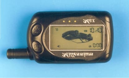
OT2MT3000R
Dec 07, 2000Car Alarm(Remote Controller)
Equipment Class
DSR - Part 15 Remote Control/Security Device Transceiver
OT2RCM-3000T
Jan 18, 2000Car Alarm
Equipment Class
DSC - Part 15 Security/Remote Control Transmitter
OT2RCM-3000R
Jan 18, 2000Car Alarm
Equipment Class
CYY - Communications Receiver used w/Pt 15 Transmitter