OU507APFH-APWireless Access Point (AP) for Medical Monitoring
GE Medical Systems Information Technologies Inc.
Click to zoom
Application Details
- Equipment Class
- TNB - Licensed Non-Broadcast Station Transmitter
- Date of Grant
- Dec 18, 2007
- Application Purpose
- Original Equipment
- Date of Application
- Dec 17, 2007
- Equipment Note
- Wireless Access Point (AP) for Medical Monitoring
- Frequency Range
- 608.66560000 - 612.89813300
- Country
- United States
Documents & Files
Document Text
Text extracted from the exhibit documents filed with the FCC. Open a document above to read the original.
Users Manual
WMTS TRANSCEIVERS PatientNet Operator’s Manual, v1.04, 10001001-003, Revision B 183 All information contained herein is subject to the rights and restrictions on the title page. WMTS TRANSCEIVERS Note:The information in this section is only applicable for Wireless Medical Telemetry Service (WMTS). About Transceivers Wireless Medical Telemetry Services (WMTS) Remote Transceivers provide the link between the patient and the Central Station through the newly approved 608 - 614 MHz Medical Telemetry frequency band. The ambulatory and bedside device trans- ceivers communicate data to the Central Station through the Access Point transceiver. In addition, the transceivers are capable of receiving control commands for self-use or connection transfer. The PatientNet ambulatory transceiver is the DT-4500. This transceiver is worn by the patient and usually carried in a gown pocket or pouch, and used with a 3, 4, or 5-wire leadset connected to the electrodes on the patient. The DT-4500 is IPX7 compliant, so it can be submerged in 1m of water for up to 30 minutes. The DT-7000 and DT-7001 are the PatientNet bedside-device transceivers and are physically connected to bedside monitors (other manufacturers’ bedside monitors and NPB 7200 series ventilator). The DR-10000 Access Point transceiver collects data from the ambulatory and bed- side transceivers, sends that data to the Central Station, and transmits control data to the transceiver devices. WARNING: Remove transceivers from patients before MRI and CAT scan procedures, and store the transceivers outside the room where such equipment is located. Close proximity to MRI or CAT scan equipment may result in damage to transceivers. Programming Transceivers Before a transceiver can be used with the PatientNet System, it must first be pro- grammed with a Network Number and Monitor I.D. number to match the correspond- ing Central Station. Consult your facility’s system administrator to perform these functions. WARNING: When programming the DT-4500 through the External Serial Device (I/O) con- nector, it must be disconnected from the patient. The accessory connector shall be kept covered when not in use with the supplied protective cover. Failure to follow these instructions could lead to excessive voltages and cur- rents being applied to the patient, resulting in cardiac arrest. The corresponding Central Station must also be programmed to this Network Number and Monitor Identification number. If you have any questions about the programming status, contact your system adminis- trator. WMTS TRANSCEIVERS 184 PatientNet Operator’s Manual, v1.04, 10001001-003, Revision B All information contained herein is subject to the rights and restrictions on the title page. Displaying Transceiver Status You can view transceiver status on the Central Station, but not on the PatientNet Viewers (also known as the IRVS and RVS). 1. Press System on the Main screen. 2. Press OpenNet button on the Passcode screen to display the OpenNet Status screen (fig. 90). Fig. 90. OpenNet Status screen Your System Administrator enables or disables the Assign TX, Program AT, and Program IT buttons. Check with your System Administrator for more information. The columns in the OpenNet Status screen are described below. Ch channel number Module ID Transceiver ID that the channel is currently set to Device ID Device ID of the transceiver from which the channel receives data Batt battery voltage of the ambulatory transceiver LL left leg electrode impedance value RA right arm electrode impedance value LA left arm electrode impedance Va chest electrode impedance value Vb, Vc miscellaneous electrode impedance value Freq Resp frequency response programmed into each transceiver Link link between the transceiver and the Central Station: OK: the Central Station is receiving data from the transceiver OFF: the Central Station is not receiving data Device Type transceiver or bedside monitor associated with the channel Version TX the download firmware version currently in the transceiver Version RX the RF Module firmware version currently in the transceiver Ch channel number WMTS TRANSCEIVERS PatientNet Operator’s Manual, v1.04, 10001001-003, Revision B 185 All information contained herein is subject to the rights and restrictions on the title page. Impedance Values The DT-4500 Ambulatory Transceivers electrode impedance values, which are displayed on the OpenNet Transceiver Status screen, indicate the quality of the signal connection and are not the actual impedance values that are measured by the system. The electrode impedance values range from 100 to 200 (optimal). The typical values range between 180 and 200. If the electrode’s impedance value is greater than the defined Quality Threshold value, then its LED is illuminated. The DT-4500 stores the Quality Threshold value and uses this value to determine whether or not the electrode LED should be illuminated when the Attendant Present buttons are pressed. See Figure 91 on page 190 for details on the DT-4500 Buttons and LED indicators. Note:A Lead Off alarm will occur when an electrode’s impedance value drops to 150 (150 is the default Loose Lead Threshold value). User Warnings, Cautions, and Notes Before operating the WMTS transceivers, read and follow all warnings and cautions presented in this section. Warnings 1. Do not use the output of the DT-4500 as a synchronization source for car- diac defibrillation. Delays in presentation of the R-Wave may be as much as 40 milliseconds. 2. Do not monitor pacer patients with a 3 wire leadset when reliable pacer detection is required. Pacer pulse detection can be erratic when only a single vector is monitored. Always use a 5 wire leadset when reliable pacer detection is required. 3. The DT-4500 is a type BF patient applied device. It is not suitable for direct cardiac application, for use in the operating room, or during car- diac surgery. Use in these environments could cause hazardous voltages and currents bein…
Text truncated - open the document above for the full version.
Cover Letter(s)
GE Medical Systems Information Technologies Federal Communications Commission P.O. Box 429 Columbia, MD 21045 July 13, 2007 Gentlemen : By signature below, we hereby appoint United States Technologies, Inc. (U.S. Tech) to act as our agent with regard to all FCC equipment authorizations. This appointment will remain in effect until otherwise notified. I further certify by signature below that no party (per 47 CFR 1.2002(b)) to the application is subject to a denial of Federal benefits, including FCC benefits, pursuant to Section 5301 of the Anti-Drug Abuse Act of 1988, 21 U.S.C. 853(a). This appointment includes the authority to complete FCC Form 731 on our behalf and sign the application as an authorized agent. Name: Matthew P. Kindschi Signature: Title: Lead Design Engineer Date: 13 July, 2007 GE Healthcare Clinical Systems Matthew Kindschi Lead Design Engineer 8200 W. Tower Ave Milwaukee, WI 53223
Cover Letter(s)
CONFIDENTIALITY REQUEST Federal Communications Commission Date: August 31, 2007 Equipment Authorization Branch 7435 Oakland Mills Road Columbia, MD 21046 Gentlemen: GE Healthcare respectfully requests confidentiality of certain materials provided with the submission of the 07APFH-AP under FCC ID: OU507APFH-AP in accordance with FCC Regulations 0.459. The confidentiality request applies to the following: Parts List, Operational Descriptions, Schematics and Block Diagrams These items are considered as Trade Secrets and therefore public access to the proprietary material could possible result in duplication of equipment that could severely damage the company's business advantage. I appreciate your assistance in this matter. Sincerely, Name: Louis A. Feudi Signature: Title: Operations Manager Date: August 31, 2007
Cover Letter(s)
Louis A. Feudi From: Kindschi, Matthew (GE Healthcare) [[email protected]] Sent: Thursday, October 04, 2007 9:42 AM To: Lou Feudi Subject: FW: Cirronet AP unit Attachments: Cirronet AP unit (8.55 KB) Page 1 of 2Cirronet AP unit 10/8/2007 Lou, I hope this helps. You already have the letter granting you authorization, so I think this will "close the loop". I have attached the message that is inline below as well, so that it can be used standalone for the FCC submission. Best regards, Matt From: Wells, Jeffrey (GE Healthcare) Sent: Thursday, October 04, 2007 8:39 AM To: Kindschi, Matthew (GE Healthcare) Subject: RE: Cirronet AP unit Matt As the authorized GE Marquette Medical Systems FCC representative I grant you the authority to act in my behalf and sign any necessary FCC documentation for the Access Point submission for the ApexPro FH telemetry system. In addition I grant you the authority to transfer the authority to act in my behalf to third party organizations that are creating support materials to support the necessary FCC documentation for the Access Point submission. Regards Jeff Wells From: Kindschi, Matthew (GE Healthcare) Sent: Thursday, October 04, 2007 7:42 AM To: Wells, Jeffrey (GE Healthcare) Subject: FW: Cirronet AP unit Jeff, Can you please send me an e-mail deputizing me to authorize Lou and USTech for the new AP FCC submission? The new proposed FCC ID in question is: OU507APFH-AP Thanks and regards, Matt From: Louis A. Feudi [mailto:[email protected]] Sent: Wednesday, October 03, 2007 4:42 PM To: Kindschi, Matthew (GE Healthcare) Subject: RE: Cirronet AP unit Hey Matt, Tim is asking for something signed by Jeff Wells either authorizing me, or authorizing you to authorize me. Thanks, Lou From: Kindschi, Matthew (GE Healthcare) [mailto:[email protected]] Sent: Wednesday, October 03, 2007 2:54 PM To: [email protected] Cc: Alan Ghasiani; Sandi; Al Patrick Subject: RE: Cirronet AP unit Hi Lou, Unfortunately you've caught me in a bit of a bind here. My laptop lease was up and I just had a new one swapped in today. So right now I don't have Acrobat or much of anything else. However, I can provide something like the attached if that will do -- let me know if you are looking for a different authorization: I think this is right. Best regards, Matt From: Louis A. Feudi [mailto:[email protected]] Sent: Wednesday, October 03, 2007 1:37 PM To: Kindschi, Matthew (GE Healthcare) Cc: 'Alan Ghasiani'; 'Sandi'; 'Al Patrick' Subject: Cirronet AP unit Matt, Tim is asking for a similar Agent Authorization letter, with the proper signatory, as was required for the SHU, listing me as Agent. Can you send one to me? Thanks, Lou Page 2 of 2Cirronet AP unit 10/8/2007
Cover Letter(s)
3505 Francis Circle Alpharetta, GA 30004 PH: 770-740-0717 Fax: 770-740-1508 www.ustech-lab.com October 3, 2007 ATCB Mr. Timothy R. Johnson RE: GE Medical Systems Information Technologies FCC ID: OU507APFH-AP Mr. Johnson: Thank you for your letter of September 28, 2007, detailing your comments regarding the above referenced application. I have included your comments in my response as reference. After a review of the submitted information, I have a few comments on the above referenced Application. Depending on your responses, kindly understand there may be additional comments. 1) Due to various concerns recently seen about proper authority being given to others for FCC and/or IC matters, the agency letter should be signed by someone traceable to have the proper authority. For instance, the FCC site shows Jeff Wells as the correct contact of authority for FCC matters. Therefore the agency letters should be signed by this contact or alternatively a letter showing who he has “deputized” to sign on his behalf may be provided as well (i.e. Matthew Kindschi). Please correct. Corrected and Uploaded with additional Correspondence. 2) Antenna information appears to discuss 2 antenna, but test photographs appear to suggest 3 configurations. Kindly explain, correct, and provide additional external photographs to document the various antennas. GE Medical chooses to remove the patch antenna from the evaluation. All attachments now specify 2 antennas. Antenna Photos added to external Photos and uploaded. 3) Please provide bottom view photographs of the RF module that are clear. Uploaded 4) The Parts list and schematics should be provided for the TX portion of the device. Please provide. Uploaded 5) A tune up procedure does not appear to be provided. Uploaded 3505 Francis Circle Alpharetta, GA 30004 PH: 770-740-0717 Fax: 770-740-1508 www.ustech-lab.com 6) Kindly provide a users manual exhibit. Uploaded 7) Please review test report cited site numbers. I believe these are incorrect. Corrected and Uploaded 8) Block diagram in the report suggests cables were present that were not seen in the test photos. Please review. Cables were present during testing. Unfortunately, the site began breakdown and the cables were inadvertently left off the photos. 9) FYI...In the future, please take test photographs closer to the table. Cable placement and other considerations can not adequately be seen. Noted 10) Test instrumentation should include appropriate calibration data. Provided 11) Unit does not appear to be labeled as required by 95.1109. Label Uploaded 12) Sub-band tables shown do not appear to stay within the sub bands cited. Please review. Corrected 13) Please explain if the device was hop-stopped during QP measurements. Yes. The unit was hop stopped on the Fundamental frequencies reported. 14) There is a concern regarding the patch data. The patch is the highest gain antenna, yet the data is over 20 dB lower at the fundamental. This leads to a concern about the validity of the configuration or if the device was operating properly. Please review. GE Medical chooses to remove the patch antenna from the evaluation. All attachments now specify 2 antennas. 15) Please review sample calculation on page 24. Corrected and Uploaded 16) Digital device emissions are normally NOT tested without an antenna attached as shown in the report. If so, then 15.111 must be applied. Testing was repeated with the antenna and data is confirmed. 3505 Francis Circle Alpharetta, GA 30004 PH: 770-740-0717 Fax: 770-740-1508 www.ustech-lab.com 17) Is the frequency tolerance given on the 731 form correct (i.e. ppm vs. Hz vs %) Corrected and Uploaded 18) Please provide appropriate occupied bandwidth measurements (i.e. 99% bandwidth or 26 dB relative to in band power). Added and Uploaded 19) Conducted power cites “about”. Please provide an appropriate data table showing conducted power as well. Added and Uploaded Please contact me with any further questions. Sincerely, Louis A. Feudi Vice President of Operations and Engineering
Cover Letter(s)
December 14, 2007 ATCB Mr. Timothy R. Johnson RE: GE Medical Systems Information Technologies FCC ID: OU507APFH-AP Mr. Johnson: Thank you for your letter of November 20, 2007, detailing your comments regarding the above referenced application. I have included your comments in my response as reference. 1. Kindly update the test photos to remove the appropriate antenna from this application Updated test photos have been uploaded. The photo of the small patch antenna has been removed. 2. Please update the test photographs for response to item 8 (i.e. retake or denote as appropriate). Test photographs have been denoted because equipment is no longer available for photo re-take. 3. Please update the AC power line conducted photographs per previous item 16 ( antenna should be present). Test photographs have been denoted because equipment is no longer available for photo re-take. 4. LISN appears out of cal during the test. Please review. The actual cal. date of the LISN was 5/10/07. A typing error was corrected in the report and the revised report was uploaded. 5. Please review sample calculation on page 24. The sample calculation has been corrected and the revised report has been uploaded. Please contact me with any further questions. Sincerely, Sandi McEnery Manager
External Photos
The following photos are attached: Photo 1. EUT, Top View Photo 2. EUT, Bottom View Photo 3 Monopole Antenna Photo 4. Circular Polarization Patch Antenna Photo 1. EUT, TopView Photo 2. EUT, Bottom View Photo 3 Monopole Antenna Photo 4. Circular Polarization Patch Antenna
ID Label/Location Info
SECTION 3 LABELING INFORMATION Label
Internal Photos
The following photos are attached: Photo 3. EUT, Top View, Cover Opened, Transceiver installed Photo 4. EUT, Bottom View, Cover Opened, Main PCB Removed Photo 5. EUT / Radio Top, Cover On Photo 6. EUT, Radio / Bottom Photo 7. EUT, Transceiver Module, Top View, Cover Off Photo 8. EUT Bottom View Cover off Photo 3. EUT, Top View, Cover Opened, Transceiver installed Photo 4. EUT, Bottom View, Cover Opened, Main PCB Removed Photo 5. EUT / Radio Top, Cover On Photo 6. EUT, Radio / Bottom Photo 7. EUT, Transceiver Module, Top View, Cover Off Photo 8. EUT Bottom View Cover off
Parts List/Tune Up Info
To Whom It May Concern: The WIT608 wireless medical telemetry device has no tunable parts. It is a highly engineered product which is tested with Automated Test Stations and determines pass or fail status. Only units that have passed are used in this product. Al Patrick Sr. Compliance Engineer Cirronet Inc. 3079 Premiere Parkway, Suite 140 Duluth, GA 30097 USA Tel: 678 684 2000 Fax: 678 684 2001 [email protected] www.cirronet.com
RF Exposure Info
7.0 RF Safety Requirements to 2.1091/95.1125 for Mobile Transmitters Part 95 transmitters are considered categorically excluded from routine environmental evaluation as given in 47 CFR 2.1091. However, the following information is presented to prove compliance with the limits. Power Output The EUT’s maximum output power as measured directly from the transmitter module is +12.2 dBm (16.7 mW). The EUT may utilize 2 different types of antenna’s (monopole @ 0 dBi, Circular Polarization Patch, -2.0 dBi). Frequency of Fundamental (MHz) Measurement (Watt)* Antenna Gain (dBi) P EIRP (Watt) 608.6656- 612.898133 0.0167 0.0 0.0167 MPE Calculations The limits for this unit (uncontrolled exposure) are 0.4 mW/cm 2 . Taking the RF Density Field Equation: S = (EIRP in mW)/(4πR 2 ) and solving for Spectrum Density S at 20 cm S = (16.7)/4*π* 20 2 S = 16.7/5026.55 Solving the above equation yields S = 0.003 mW/cm 2 Since the EUT is designed only for mobile applic ations (where the expected separation distance between antenna and humans is greater than 20 cm), all manual instructions have specified 20 cm as the minimum exposure distance.
Test Report
Page 1 of 34 GE HealthCare FCC Part 95 Application Model 07APFH-AP June 19, 2007 3505 Francis Circle Alpharetta, GA 30004 PH: 770-740-0717 Fax: 770-740-1508 www.ustech-lab.com FCC ID: OU507APFH-AP Page 2 of 34 MEASUREMENT/TECHNICAL REPORT COMPANY NAME: GE HealthCare MODEL: 07APFH-AP FCC ID: OU507APFH-AP DATE: June 19, 2007 This report concerns (check one): Original grant X Class II change ____ Equipment type: Low Power Transmitter (for Biomedical Applications) Deferred grant requested per 47 CFR 0.457(d)(1)(ii)? yes_____ No X If yes, defer until:_________________ date N.A. agrees to notify the Commission by N.A. date of the intended date of announcement of the product so that the grant can be issued on that date. Report prepared by: United States Technologies, Inc. 3505 Francis Circle Alpharetta, GA 30004 Phone Number: (770) 740-0717 Fax Number: (770) 740-1508 FCC ID: OU507APFH-AP Page 3 of 34 TABLE OF CONTENTS LETTER OF CONFIDENTIALITY SECTION 1 GENERAL INFORMATION Product Description SECTION 2 TESTS AND MEASUREMENTS Configuration of Tested Test Facility Modifications Test Equipment Modifications Antenna Description Field Strength of Fundamental Field Strength of Spurious Emissions Radiated Digital Device Emissions Power Line Conducted Emissions for Digital Device, Transmitter, and Receiver Emissions Type Frequency Stability SECTION 3 LABELING INFORMATION SECTION 4 BLOCK DIAGRAM(S)/SCHEMATICS SECTION 5 THEORY OF OPERATION SECTION 6 PHOTOGRAPHS SECTION 7 RF EXPOSURE INFORMATION SECTION 8 USER'S MANUAL FCC ID: OU507APFH-AP Page 4 of 34 LIST OF FIGURES AND TABLES FIGURES Test Configuration Photograph(s) for Fundamental, Spurious, and Digital Device Emissions Photograph(s) for Conducted Emissions Field Strength of Fundamental Emission Field Strength of Spurious Emissions TABLES EUT and Peripherals Test Instruments Field Strength of Fundamental Emission Field Strength of Spurious Emissions Radiated Digital Device Emissions Power Line Conducted Emissions for Digital Device, Transmitter, and Receiver FCC ID: OU507APFH-AP Page 5 of 34 SECTION 1 GENERAL INFORMATION FCC ID: OU507APFH-AP Page 6 of 34 GENERAL INFORMATION Product Description The Equipment Under Test (EUT) is a GE Healthcare, 07APFH-AP. The 07APFH-AP is a wireless Access Point (AP) designed for use in medical monitoring applications. The 07APFH-AP receives patient monitoring data from similar radios attached to the patients in the hospital. The 07APFH-AP is linked to other 07APFH-AP through a 10Base-T Ethernet backbone. This backbone allows the AP's to pass patient data back to the end user of the system - a nurses monitoring station. The 07APFH-AP is composed of a 608-614 MHz wireless transceiver and Ethernet conversion circuitry that passes data from the transceiver to the Ethernet backbone. The 07APFH-AP may operate with three different types of antennas: a 0 dBi monopole to provide omni-directional coverage, a +2 dBi patch antenna to provide unidirectional coverage, and a -2 dBi Circular polarization Patch. The unit requires external DC power but has its own internal voltage regulation. The 07APFH-AP is self contained in a metal package and is designed to be installed on the ceiling of a hospital hallway. FCC ID: OU507APFH-AP Page 7 of 34 Related Submittal(s)/Grant(s) None FCC ID: OU507APFH-AP Page 8 of 34 SECTION 2 TESTS AND MEASUREMENTS FCC ID: OU507APFH-AP Page 9 of 34 TESTS AND MEASUREMENTS Configuration of Tested System Since Part 95 stipulates radiated field strength limits and not dBc limits. Therefore as allowed by 2.947(a)(3), the sample was tested per ANSI C63.4, Methods of Measurement from Low-Voltage Electrical and Electronic Equipment in the Range of 9 kHz to 40 GHz (2003). Please note that the FCC has also shown a history of accepting other applications using ANSI C63.4 as the test methodology for devices tested under 95.1115. Conducted and radiated emissions data were taken with the test receiver or spectrum analyzer's resolution bandwidth adjusted to 9 kHz and 120 kHz, respectively. All measurements are peak unless stated otherwise. The video filter associated with the spectrum analyzer was off throughout the evaluation process. Interconnecting cables were manipulated as necessary to maximize emissions. A block diagram of the tested system is shown in Figure 1. Test configuration photographs for spurious and fundamental emissions are shown in Figure 2. Test Facility Testing was performed at US Tech's measurement facility at 3505 Francis Circle, Alpharetta, GA. This site has been fully described and registered with the FCC, under designation number US5117. Additionally this site has also been fully described and submitted to Industry Canada (IC), and has been approved under file number 2982A-1. Modifications No modifications were made to the EUT for compliance with FCC Part 95. Test Equipment Table 2 describes test equipment used to evaluate this product. FCC ID: OU507APFH-AP Page 10 of 34 FIGURE 1 TEST CONFIGURATION Transceiver (EUT) AC Adapter #1 Laptop Computer AC Adapter #2 Monopole Antenna 120 VAC 60 Hz Direct Plug In 120 VAC 60 Hz 6' U 3' S 1 m U Ethernet Term 6' U 3’ S 50 Ohm Term 6' S 6’ U Alternatively, the monopole antenna and its cable may be replaced by a circular polarization patch antenna FCC ID: OU507APFH-AP Page 11 of 34 TABLE 1 EUT and Peripherals PERIPHERAL MANUFACTURER MODEL NUMBER SERIAL NUMBER FCC ID: CABLES P/D Transmitter GE HealthCare (EUT) 07APFH-AP None OU507APFH-AP (Pending) 6' S 3' S 50 Ohm Term. 1 m U, Ethernet Term Antenna Nearson, Inc. P-24A48G (Monopole, 0 dBi) None None None Antenna GE Healthcare EA-ANT-600- 6G-OMN (Circular Polar Patch, -2 dBi) 0645061 N/A 2’ S AC Adapter #1 Dell 55522 P38312318777 N/A 6' U Power Cord AC Adapter #2 Volgen SPU10R-2 None N/A 6’U Direct Plug In Computer Dell Inspiron 3200 TS3043 IIRTS30HT 6' U FCC ID: OU507APFH-AP Page 12 of 34 TABLE 2 TEST INSTRUMENTS TYPE MANUFACTURER MODEL SN. Last Calibration Date SPECTRUM ANALYZER HEWLETT-PACKARD 8593E 3205A00124…
Text truncated - open the document above for the full version.
Test Setup Photos
FIGURE 2a Photograph(s) for Fundamental, Spurious and Digital Devices Emissions Monopole Configuration * Note: Actual testing conducted with cables attached that are not shown in these photos. FIGURE 2b Photograph(s) for Fundamental, Spurious and Digital Devices Emissions Circular Polarization Patch Configuration * Note: Actual testing conducted with cables attached that are not shown in these photos. FIGURE 2c Photograph(s) for Conducted Emissions * Note: Testing conducted with antenna. Photo with antenna not available.
Contact Information
Applicant
Matthew R Pekarske(Principal of Connectivity and Service Technology)
Technical Contact
United States TechnologiesSandy McEnery
[email protected]7707400717
3505 Francis Circle · Alpharetta · United States
Test Firm
US TechGeorge Yang
Technical Specifications
| # | Rule Parts | Frequency Range | Power Output | Emission | Tolerance |
|---|---|---|---|---|---|
| 1 | 95H | 608.6656 MHz - 612.898133 MHz | 17.00 mW | 300KFXD | 1.6000000000 ppm |
Other Applications from GE Medical Systems Information Technologies Inc.

OU5-5406102
Jan 10, 2011URP Detector UWB Radio PWA and Antenna Module
Equipment Class
UWB - Ultra Wideband Transmitter
OU52014748-002
Dec 18, 2007Medical Telemetry Transmitter
Equipment Class
TNT - Licensed Non-Broadcast Transmitter Worn on Body
OU5SHU-WMTS
Sep 09, 2007EA-WMTS-SHU-4
Equipment Class
TNB - Licensed Non-Broadcast Station Transmitter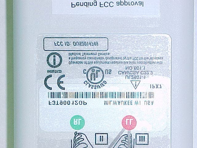
OU52014748
Aug 25, 2003Medical Telemetry Transmitter worn on body
Equipment Class
TNT - Licensed Non-Broadcast Transmitter Worn on Body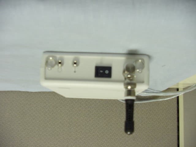
OU5340MT
Sep 30, 2002WMTS Transmitter
Equipment Class
TNT - Licensed Non-Broadcast Transmitter Worn on Body