OU5SHU-WMTSEA-WMTS-SHU-4
GE Medical Systems Information Technologies Inc.
Click to zoom
Application Details
- Equipment Class
- TNB - Licensed Non-Broadcast Station Transmitter
- Date of Grant
- Sep 09, 2007
- Application Purpose
- Original Equipment
- Date of Application
- Sep 08, 2007
- Equipment Note
- EA-WMTS-SHU-4
- Frequency Range
- 608.00000000 - 614.00000000
- Country
- United States
Documents & Files
Document Text
Text extracted from the exhibit documents filed with the FCC. Open a document above to read the original.
Users Manual
ApexPro ™ Telemetry System Operator’s Manual Software Version 3 2001989-134Revision D T-2ApexPro Telemetry SystemRevision D 2001989-13412 March 2004 NOTE: The information in this manual only applies to ApexPro Telemetry System software version 3. It does not apply to earlier software versions. Due to continuing product innovation, specifications in this manual are subject to change without notice. Listed below are GE Medical Systems Information Technologies trademarks. All other trademarks contained herein are the property of their respective owners. APEX, ApexPro, DINAMAP Pro, and UNITY NETWORK are trademarks of GE Medical Systems Information Technologies registered in the United States Patent and Trademark Office. CD Telemetry ® -LAN, CIC Pro, IMPACT.wf, PRN 50 are a trademarks of GE Medical Systems Information Technologies. © GE Medical Systems Information Technologies, 2003, 2004. All rights reserved. Revision DApexPro Telemetry SystemCE-1 2001989-134 CE Marking Information CE Marking Information Compliance The ApexPro telemetry system bears CE mark CE-0459 indicating conformity with the provisions of the Council Directive 93/42/EEC concerning medical devices, and fulfills the essential requirements of Annex I of this directive. The product is radio-interference protection class A in accordance with EN 55011. The country of manufacture can be found on the equipment labeling. The product complies with the requirements of standard EN 60601-1-2 “Electromagnetic Compatibility-Medical Electrical Equipment.” The safety and effectiveness of this device has been verified against previously distributed devices. Although all standards applicable to presently marketed devices may not be appropriate for prior devices (i.e. electromagnetic compatibility standards), this device will not impair the safe and effective use of those previously distributed devices. See user's information. CE-2ApexPro Telemetry SystemRevision D 2001989-134 CE Marking Information Exceptions The CIC Pro and ApexPro server is suitable for use in the specified electromagnetic environment. The customer and/or the user of the CIC Pro and ApexPro server should assure that it is used in an electromagnetic environment as described below: CE Exception Table EN60601-1-2 Clause 36ExceptionElectromagnetic Environment Guidance 36.202.1 Immunity: ESDDirect - Discharges of 6 KV or greater to the rear I/O connector area may cause the system to lock up, thus experiencing loss of data and loss of functionality. Operator intervention may be required. Likelihood of occurrence: Remote During testing there were 2 occurrences out of 1,920 discharges. The rear I/O connector area is not considered to be user accessible during normal operation. Floors should be wood, concrete, or ceramic tile. If floors are covered with synthetic material, the relative humidity should be at least 30 %. 36.202.3.1 Immunity: Fast Transient Transients on the AC power line of +/- 1 KV or higher may cause momentary network packet loss (i.e. waveform and/or numeric data), thus experiencing momentary loss of data at the time of the surge. Mains power quality should be that of a typical commercial and/or hospital environment. 36.202.3.2 Immunity: Fast SurgesSurges on the AC power line of +/- 1 KV or higher may cause momentary network packet loss (i.e. waveform and/or numeric data), thus experiencing momentary loss of data at the time of the surge. Mains power quality should be that of a typical commercial and/or hospital environment. Revision DApexPro Telemetry SystemCE-3 2001989-134 CE Marking Information ApexPro and ApexPro CH Transmitters 36.202.2 Immunity: Radiated FieldsIf operated in the midst of the conditions outlined in EMC standard EN60601-1-2 (Radiated Immunity 3 V/m), fields in excess of 1 V/m may cause waveform distortions and erroneous numeric data at various electromagnetic interference (EMI) frequencies. Review the AAMI EMC Committee technical information report (TIR-18) titled Guidance on electromagnetic compatibility of medical devices for clinical/biomedical engineers - Part 1: Radiated radio-frequency electromagnetic energy. This TIR provides a means to evaluate and manage the EMI environment in the hospital. Manage (increase) distance between sources of EMI and susceptible devices. Manage (remove) devices that are highly susceptible to EMI. Lower power from internal EMI sources under hospital control (i.e., paging systems). Label devices susceptible to EMI. Educate staff (nurses and doctors) to be aware of, and to recognize, potential EMI related problems. ApexPro Antenna System 36.202.2 Immunity: Radiated FieldsIf operated in the midst of the conditions outlined in EMC standard EN60601-1-2 (Radiated Immunity 3 V/m), fields in excess of 0 V/m in the frequency ranges of 520-534 MHz and 645-660 MHz may cause loss of telemetry. Review the AAMI EMC Committee technical information report (TIR-18) titled Guidance on electromagnetic compatibility of medical devices for clinical/biomedical engineers - Part 1: Radiated radio-frequency electromagnetic energy. This TIR provides a means to evaluate and manage the EMI environment in the hospital. Manage (increase) distance between sources of EMI and susceptible devices. Manage (remove) devices that are highly susceptible to EMI. Lower power from internal EMI sources under hospital control (i.e., paging systems). Label devices susceptible to EMI. Educate staff (nurses and doctors) to be aware of, and to recognize, potential EMI related problems. CE Exception Table EN60601-1-2 Clause 36ExceptionElectromagnetic Environment Guidance CE-4ApexPro Telemetry SystemRevision D 2001989-134 CE Marking Information Apex Oximeter 36.202.2 Immunity: Radiated FieldsIf operated in the midst of the conditions outlined in EMC standard EN60601-1-2 (Radiated Immunity 3 V/m), fields in excess of 0.5 V/m may cause waveform distortions and erroneous numeric data at various electromagnetic interference (EMI) frequencies. Revi…
Text truncated - open the document above for the full version.
Users Manual
7-10ApexPro Telemetry SystemRevision D 2001989-134 Admit/View a Patient: Discharge Instructions Clearing a Patient Window To clear discharged patient information from the window and bring up the Admit button, use the right-click menu. 1. Use the RIGHT mouse button to click anywhere inside a discharged bed window. The right-click menu appears. 2. Slide the mouse over the Select Care Unit, then Bed Number text, without pressing either mouse button. The text highlights, and a list of units on the network pops up. 3. Without pressing either mouse button, slide the mouse pointer to None at the bottom of the list. Click the left mouse button on None. 4. The popup list closes, and the patient window will now be empty, except for an Admit button. NOTE On a locked bed, None is not an option. When beds are locked, you must discharge from the single patient viewer. 387A Revision DApexPro Telemetry System7-11 2001989-134 Admit/View a Patient: Move Telemetry Patients Move Telemetry Patients This option allows you to move a telemetry patient to a new bed within the same care unit or to move Combo patients in and out of combo mode. The Move feature is located on the Admit tab sheet on the CIC Pro. To move a patient within the same care unit, follow this procedure: 1. At the CIC Pro, select the bed window of the patient you wish to move. 2. Click on the Admit tab to bring the tab sheet to the front. 3. Select a new bed from the Location Bed: list. 4. The Save button changes to Move, click Move to move the patient to the bed you selected from the bed list. 5. Select Yes when the Patient Move dialog is displayed. Admit Patient Tab Sheet A patient can not be moved to an unlocked bed if no bed slot is available. A dialog window appears indicating that the change is disallowed because the patient would be unmonitored. Moving Locked/Unlocked Beds The following guide lines apply when moving locked and unlocked beds. A patient can be moved from an unlocked bed to another available unlocked bed. A patient can be moved from a locked bed to another available locked bed. A patient can be moved from an unlocked bed to an available locked bed. 126A 7-12ApexPro Telemetry SystemRevision D 2001989-134 Admit/View a Patient: Viewing a Patient Viewing a Patient When you wish to see detailed information about a patient’s status, you can use the View Patient tab in the single patient viewer. 1. Click in the bed window of the patient you wish to view. The display rearranges to accommodate the single patient viewer at the bottom. 2. Click on the View Patient tab to bring it to the front. The View Patient tab sheet shows all the information that normally appears in patient’s bed window in the multiple patient viewer, and also displays up to eight leads of ECG waveforms. There are two buttons in the View Patient tab sheet that can be used for telemetry patients. Their functions are described below. NOTE The third button, View All ECG, is dimmed when viewing telemetry patients because all the ECG waveforms available for telemetry patients are normally displayed. Sample Clicking on the Sample button records a sample of the patient’s real-time ECG data. This sample is then stored in alarm histories, and can be viewed in the Alarm Histories tab sheet under the title of Sample. For more information about viewing alarm histories, refer to Chapter 10, Patient Data, in this manual. 348D Revision DApexPro Telemetry System7-13 2001989-134 Admit/View a Patient: Viewing a Patient Relearn Clicking on the Relearn button initiates a relearn of the patient’s ECG rhythm. The relearn takes only a few seconds. The patient’s heart rate reading will appear as Xs momentarily, and then be replaced by numerics once the relearn is complete. Use the relearn function whenever there has been a significant change in the patient’s normal rhythm. 7-14ApexPro Telemetry SystemRevision D 2001989-134 Admit/View a Patient: Viewing Another Patient Viewing Another Patient NOTE When viewing a patient from another unit, you cannot make any changes to the patient’s information or settings. Viewing in the Single Patient Viewer To display the single patient viewer of a patient on the network who is not currently displayed on your CIC Pro, follow the steps below. 1. Click on the View Other button in the Main Menu at the bottom of the CIC Pro display. 2. The View Other Patient window appears. This window displays all the units currently available on your network. 3. Click on the next to the unit from which you wish to view a bed. A list of beds admitted to that unit appears below the unit name. NOTE If a unit name has a next to it but no bed list below it, there are no beds admitted into that unit. 4. Click on the bed name you wish to view. The name is highlighted. 5. Click on the OK button. The single patient viewer opens at the bottom of the display, showing the viewed patient’s data. 339B Revision DApexPro Telemetry System7-15 2001989-134 Admit/View a Patient: Viewing Another Patient Viewing in the Multiple Patient Viewer When in the multiple patient viewer, you can replace the data in any unlocked bed window with the data from another patient on the network who is not currently displayed on your CIC Pro. NOTE The data for the patient who was originally displayed in the bed window you select will not be visible on your CIC Pro once you use that patient’s bed window to view another patient. To view another patient in the multiple patient viewer, follow the steps below. 1. Use the right mouse button to click anywhere inside a bed window. The right-click menu appears. NOTE You must use the right mouse button to access the right-click menu. 2. Slide the mouse over the Select Care Unit then Bed Number text, without pressing either mouse button. The text highlights, and a list of units on the network pops up. 349A 7-16ApexPro Telemetry SystemRevision D 2001989-134 Admit/View a Patient: Viewing Another Patient 3. Without pressing either mouse button, slide the mouse pointer…
Text truncated - open the document above for the full version.
Cover Letter(s)
GE Medical Systems Information Technologies Federal Communications Commission P.O. Box 429 Columbia, MD 21045 July 13, 2007 Gentlemen : By signature below, we hereby appoint United States Technologies, Inc. (U.S. Tech) to act as our agent with regard to all FCC equipment authorizations. This appointment will remain in effect until otherwise notified. I further certify by signature below that no party (per 47 CFR 1.2002(b)) to the application is subject to a denial of Federal benefits, including FCC benefits, pursuant to Section 5301 of the Anti-Drug Abuse Act of 1988, 21 U.S.C. 853(a). This appointment includes the authority to complete FCC Form 731 on our behalf and sign the application as an authorized agent. Name:Matthew P. KindschiSignature: Title: Lead Design EngineerDate:13 July, 2007 GE Healthcare Clinical Systems Matthew Kindschi Lead Design Engineer 8200 W. Tower Ave Milwaukee, WI 53223
Cover Letter(s)
From: Wells, Jeffrey (GE Healthcare) To: [email protected]; cc: Kindschi, Matthew (GE Healthcare); timothyrjohnson@comcast. net; Subject: GE Healthcare FCC grant for WMTS SHU on ApexPro FH product Date: Tuesday, August 21, 2007 10:55:19 AM Tim Per your discussion with Matt Kindschi, I am granting Matt the authority to be a representative for GE Healthcare for the FCC grant on the WMTS SHU for the ApexPro FH product. Any FCC correspondence requiring GE Healthcare acknowledgement or approval can be provided by Matt for this grant. Regards Jeff Wells Engineering Manager Systems and Wireless GE Healthcare 1-414-362-2497 [email protected]
Cover Letter(s)
GE Medical Systems Information Technologies American TCB 6731 Whittier Ave Suite C110 McLean, VA 22101 August 28, 2007 Dear Gentlemen : In regards to the exhibits submitted in support of the application for FCC ID: OU5SHU-WMTS, please classify the following as confidential under the provision of 47 CFR 0.459: 1.) The Operational Description information 2.) The GE Healthcare Enterprise Access™ EA-WMTS-SHU-4 Installation Instructions; GE p/n 2028835-160. Sincerely, Matthew P. Kindschi Lead Design Engineer GE Healthcare Clinical Systems 8200 W. Tower Ave Milwaukee, WI 53223
Cover Letter(s)
3505 Francis Circle Alpharetta, GA 30004 PH: 770-740-0717 Fax: 770-740-1508 www.ustech-lab.com 8/31/2007 Mr. Timothy R. Johnson ATCB RE: GE Medical Systems Information Technologies FCC ID: OU5SHU-WMTS Mr. Johnson, Thank you for your comments in your letter of August 17, 2007. Below is my response to your comments on this application. I have included your original comments in my response. In some instances, GE Medical Systems has responded directly, and the below statements is confirmation of their response. 1) Due to various concerns recently seen about proper authority being given to others for FCC and/or IC matters, the agency letter should be signed by someone traceable to have the proper authority. For instance, the FCC site shows Jeff Wells as the correct contact of authority for FCC matters. Therefore the agency letters should be signed by this contact or alternatively a letter showing who he has “deputized” to sign on his behalf may be provided as well (i.e. Matthew Kindschi). Please correct. Corrected - see uploaded e-mail from Jeff Wells, dated 8/21/2007, provided by GE Medical Systems Information Technologies. 2) Currently the confidentiality letter asks for: Schematics, Parts List, Block Diagrams, and Tune Up Procedures. It may be prudent to add Operational Description to this to cover various technical documentation. If necessary, please update the confidentiality Letter. Corrected and Uploaded. See both the GE and MobileAccess confidentiality letters, and the Operational Description, supplied by GE Medical Systems Information Technologies. 3) Kindly explain what the black box device attached to the back of the board is? Provided by MobileAccess Networks, Inc. 4) There should be technical information for licensed device to explain the following as applicable: “A description of all circuitry and devices provided for determining and stabilizing frequency, for suppression of spurious radiation, for limiting modulation, and for limiting power been provided (2.1033(c)(10) and for equipment employing digital modulation techniques, a detailed description of the modulation system to be used, including the response characteristics (frequency, phase and amplitude) of any filters provided, and a description of the modulating wavetrain, been provided for the maximum rated conditions at which the equipment will be operated? (2.1033(c)(13).” While some of this may not be directly applicable, an overall description should be provided. [This has been requested from Mobile Access] Provided by MobileAccess Networks, Inc. 3505 Francis Circle Alpharetta, GA 30004 PH: 770-740-0717 Fax: 770-740-1508 www.ustech-lab.com 5) Please provide information regarding both DC voltages AND currents applied into the several elements of the final radio frequency amplifying device for normal operation over the power range been provided? (2.1033(c)(8)). [This has been requested from Mobile Access] Provided by MobileAccess Networks, Inc. 6) Please provide an appropriate RF exposure exhibit as required by 95.1125. Uploaded. 7) References in the first paragraph of 2.6 are relative to Part 15 type of devices only. While the majority of information is necessary and relevant to this application, the paragraph should be reviewed and adjusted as necessary. Report adjusted and uploaded 8) Report and 731 form cites 15.8 mW (12.0 dBm), while description in test report cites +17 dBm output/+5 dBm input min, and test plan cites +17 dBm. FCC expects device to be tested with maximum output. However the report mentions that the power had to be reduced to pass to 12 dBm. How will the maximum setting be set and utilized in the final equipment? Where is this set or measured? Please explain. Proposed Test plan cited 17 dBm with reduction of power by compensating for minimum cable length, until unit met fundamental radiated power and Spurious Harmonics. EUT allowed reduction of output power by software means. Final output power was measured when fundamental and spurious emissions were met and it is this value that has replaced the conducted power plots. Report corrected and uploaded. Using a TDR measurement of the cable length from the SHU to the antenna, and a typical 600 MHz attenuation per 100 ft in dB, a loss for the given cable from the SHU to the antenna is calculated. SHU output power is adjusted to the quantity (12 dBm + the conductive loss between the antenna), rounded down to the nearest integer, using a spreadsheet provided to the professional installer. Output power is thereby controlled as to not exceed 12 dBm conducted into the antenna. 9) Given 8) above, why does table 3A cite 13 dBm? 13 dBm was the original output software setting when testing 1-1, 1-2, 1-3, and 1-4 configurations. However, 2-2 was found to be worst case, and required an additional -1dB correction in output power software setting. Since 13 dBm met in the 1-1through4 configuration, this data was kept. Explanation added to report, corrected and uploaded 10) It is uncertain where the 12.0 dBm listed above has been measured. For instance some information suggests that this was measured at the end of the cable installed (at antenna connection). Please explain. 3505 Francis Circle Alpharetta, GA 30004 PH: 770-740-0717 Fax: 770-740-1508 www.ustech-lab.com As stated above, output power is now measured at the output of the cable with the software setting at 12 dBm. Report corrected and uploaded 11) If power was measured at the end of the cable and only a short cable was utilized, what happens if 100’+ was used. What would the output power be adjusted to? If the power is measured at the end of the cable, then this means that higher power would be coming directly from the unit. This would mean that tests of case radiation would not have been properly maximized using a short cable. Please review/explain. After review, case radiation was measured and found to be insignificant at 17 dBm (software output setting). This data has been added to the report and uploaded.…
Text truncated - open the document above for the full version.
Cover Letter(s)
[email protected], 05:12 PM 2/6/2007 -0500, WMTS-SHU Part 95 Device Printed for "Timothy R. Johnson" <[email protected]>1 To: [email protected] From: "Timothy R. Johnson" <[email protected]> Subject: WMTS-SHU Part 95 Device Cc: Bcc: Attached: C:\Documents and Settings\Tim Johnson\My Documents\ATCB Folder\ATCB Local Download\_To_FARM_OUT\___GE - US Tech\Discussion Items with FCC - v3.0.pdf; C:\Documents and Settings\Tim Johnson\My Documents\ATCB Folder\ATCB Local Download\_To_FARM_OUT\___GE - US Tech\email from Joe Dichoso 0107.pdf; To Whom It May Concern, Due to the nature of the rules, the device/system, and desires of the manufacturer - guidance is requested from the FCC to ensure the device is approved and tested appropriately. Per conversations with Joe Dichoso, we are submitting information regarding an upcoming approval and need guidance from the FCC for certain aspects of the approval and/or test plan. Additionally, the test lab will follow up with an appropriate test plan soon, based upon the response to the attached. Thank You in Advance, Timothy R. Johnson, NARTE Certified EMC Engineer (No. EMC-002205-NE) Examining Engineer American TCB, Inc. 6731 Whittier Ave. McLean, VA 22101 email: [email protected] alternate email: [email protected] USA direct number: 404-414-8071 USA corporate phone: 703-847-4700 USA corporate fax: 703-847-6888
Cover Letter(s)
Tim, a quick note.... I just talked to Tim Maguire. He will be sending you an e-mail soon. Looks like amplifier will be allowed but you will need to show how field strength limits will be met via professional install. Possibly limiting output power and antenna gain. -Joe Subject: RE: RE: Update RE: FCC Approval SHU-4 WMTS From: Joe Dichoso <[email protected]> To: Timoth y R. Johnson <[email protected]>
Cover Letter(s)
X-Ninja-PIM: Scanned by Ninja X-Ninja-Antispam: Policy 1 - Allowed - Custom Allow (Global) - 0,0,0 (0) X-Ninja-AttachmentFiltering: (no action) Subject: RE: RE: FYI regarding WMTS-SHU Part 95 Device Date: Thu, 5 Apr 2007 22:54:38 -0400 Thread-Topic: RE: FYI regarding WMTS-SHU Part 95 Device Thread-Index: AcdyK7xjjD7A+fyBRUyUBnaRyrziFQAHj8jwASjV2L0AJ0ZKgAACYGggAA051hAACzG2UA== From: Tim Maguire <[email protected]> To: Jeff Tobias <[email protected]>, [email protected] Cc: Joe Dichoso <[email protected]> X-OriginalArrivalTime: 06 Apr 2007 02:54:39.0370 (UTC) FILETIME=[EB1F36A0:01C777F6] Tim, After discussing your clients device internally, we've decided that it should be tested as an amplifier. Each antenna output should be tested independently to show compliance with 95.1115(a). Test the unit as you would any other amp, with intermod, signal spreading tests, etc. The grant will contain a note requiring professional installation to help ensure compliance with Part 95 rules. I'll be out of the office until Wednesday next week, contact Joe if you have any testing questions. Tim Maguire Electronics Engineer Mobility Division Wireless Telecommunications Bureau (202) 418-2155 [email protected]
Cover Letter(s)
1 Louis A. Feudi From: Tim Maguire [[email protected]] Sent: Monday, May 07, 2007 11:56 AM To: Joe Dichoso; Timothy R. Johnson; Louis A. Feudi Cc: Jeff Tobias; Rashmi Doshi; Steven Dayhoff; Tim Harrington; William Hurst Subject: RE: RE: Proposed Test Plan for SHU Joe, I agree, this sounds reasonable. Thanks, Tim Tim Maguire Electronics Engineer Mobility Division Wireless Telecommunications Bureau (202) 418-2155 [email protected] -----Original Message----- From: Joe Dichoso Sent: Mon 5/7/2007 10:36 AM To: 'Timothy R. Johnson'; 'Louis A. Feudi'; Joe Dichoso; Tim Maguire Cc: Jeff Tobias; Rashmi Doshi; Steven Dayhoff; Tim Harrington; William Hurst Subject: RE: RE: Proposed Test Plan for SHU Tim, I don't want to speak for the Wireless Bureau but I wouldn't have an issue with if the information requested in Item 5 is used to ensure compliance with the field strength limits. In other words, if the professional installation configurations ensured non- overlap of identical signals by indicating antenna separation distances AND antenna direction and antenna type in order to comply with the field strength limits, this could be acceptable if the grant was conditioned accordingly and WB approves. -Joe ________________________________ From: Timothy R. Johnson [mailto:[email protected]] Sent: Friday, May 04, 2007 10:02 PM To: Joe Dichoso; Louis A. Feudi Cc: Tim Maguire; Jeff Tobias; Rashmi Doshi; Steven Dayhoff; Tim Harrington; Joe Dichoso; William Hurst Subject: RE: RE: Proposed Test Plan for SHU Joe or Tim M, I'm letting the lab handle most of the test matrix, but I wanted to get clarification of one ite.....You mentioned aggregate power, but remember the limits here are in field strength and the antennas will be installed a far distance apart from each other (reasonable to say 100'+, but we can get GE to define this as we move forward) and would NOT be expected to have direct additive contribution from the antenna elements themselves. If the manufacturer is specifying a minimum distance apart, for purposes of testing where multiple antennas TX the same info, can the additional antennas be terminated and measurements made this way? This would allow proper investigation of case radiation, a 2 single antenna element, and contributions made by cables as well. Note that a typical path loss would expect to have > 20 dB drop between installation points and therefore expected to have negligible direct contribution from additional antenna elements themselves when installed per the manufactures requirements (and also professional installation would apply as well) If this is not acceptable, then I would propose locating additional TX radiated elements away at the specified minimum distance given by the manufacturer. However this would overly tend to complicate test setup issues, especially when dealing with > 2 simultaneous elements. Any guidance you can provide on this issue would be appreciated. Thank You, Tim At 02:22 PM 5/4/2007 -0400, Joe Dichoso wrote: Hello Louis, Here are the comments to the test plan. You can submit the changes at www.fcc.gov/labhlep if you need a confirmation of the final plan. Thanks all, Joe 1) When measuring the fundamental field strength, a Quasi-peak (QP)detector is used if the bandwidth of the signal is less than the bandwidth of the QP instrumentation. The bandwidth of the QP instrumentation is based on the frequency of measurement. E.g. Per ANSI C63.4, the QP detector bandwidth is 100 kHz from 30-1000 MHz and 1 MHz above 1 GHz. When the emission bandwidth is greater than the QP instrumentation bandwidth, an average detector is used and the RBW of the analyzer must be greater than the emission bandwidth. 2) When an Access point is connected to multiple antennas and is sending the same information on the same channel to all antennas, the field strength to all connected antennas must be aggregated and compared to the field strength limit. 3) Please specify all antennas and the FCC identifiers of the access points used with the device. 4) For out of band emissions tests, test each modulation type and each antenna type, test at the maximum input on the lowest, a middle and the highest channel. The lowest and highest channels is to show compliance at the bandedges. The grant will list each emission designator and the allowed frequency range from the lowest to the highest center frequency. 5) Provide the professional installation instructions to ensure that it agrees with the test plan. Make any necessary corrections or modifications to ensure that they agree. The instructions should include the type of access point, antenna and output power adjustments necessary to meet all appropriate limits. 6) The test plan indicates an input range of 5-15 dBm, testing must be done at maximum input. 7) FYI.The test plan indicates an output of 17 dBm. With a O dBi antenna, the EIRP would be 17 dBm and would not meet the field strength limit. ________________________________ From: Louis A. Feudi [ mailto:[email protected] <mailto:[email protected]> ] Sent: Tuesday, April 24, 2007 9:13 AM To: Joe Dichoso; 'Timothy R. Johnson' Cc: Tim Maguire; Jeff Tobias Subject: RE: RE: Proposed Test Plan for SHU Joe, Hello. 3 Word Document attached. Lou ________________________________ From: Joe Dichoso [ mailto:[email protected] <mailto:[email protected]> ] Sent: Tuesday, April 24, 2007 8:53 AM To: Timothy R. Johnson; [email protected] Cc: Tim Maguire; Jeff Tobias Subject: RE: RE: Proposed Test Plan for SHU Tim, Can you please send me the test plan as a word document so that comments can be made directly on it. Thanks, Joe ________________________________ From: Timothy R. Johnson [ mailto:[email protected] <mailto:[email protected]> ] Sent: Tuesday, April 24, 2007 3:14 AM To: Joe Dichoso; [email protected] Cc: Tim Maguire; Jeff Tobias; [email protected] Subject: Fwd: RE: Proposed Test Plan for SHU Joe, Attached is a test plan generated by U.S. Tech and their client for the GE Part 95 appl…
Text truncated - open the document above for the full version.
Cover Letter(s)
X-Ninja-PIM: Scanned by Ninja X-Ninja-Antispam: Policy 1 - Allowed - Custom Allow (Global) - 0,0,0 (0) X-Ninja-AttachmentFiltering: (no action) Subject: RE: RE: Proposed Test Plan for SHU Date: Tue, 4 Sep 2007 17:09:05 -0400 Thread-Topic: RE: Proposed Test Plan for SHU Thread-Index: AcfsNsVnR75LP9kERjm7j9NlLpteOAC5VVvQ From: Tim Maguire <[email protected]> To: Timothy R. Johnson <[email protected]> Cc: Joe Dichoso <[email protected]>, "Fitzgerald, Ari Q." <[email protected]>, "Seidl, Neal (GE Healthcare)" <[email protected]>, [email protected], [email protected] X-OriginalArrivalTime: 04 Sep 2007 21:09:06.0710 (UTC) FILETIME=[D4485B60:01C7EF37] Priority: Urgent Tim, After discussing this internally with the Lab, and reviewing the WMTS rulemaking, we agree that a QP measurement is permitted for WMTS devices operating in the 608-614 MHz band (95.1115(a)…
Text truncated - open the document above for the full version.
Contact Information
Applicant
Matthew R Pekarske(Principal of Connectivity and Service Technology)
Technical Contact
United States Technologies, Inc.Lou Feudi
[email protected]770-740-0717
2505 Francis Circle · Alpharetta · United States
Non-Technical Contact
United States Technolgoies, Inc.Sandi McEnery
[email protected]770-740-0717
Test Firm
US TechGeorge Yang
Technical Specifications
| # | Rule Parts | Frequency Range | Power Output | Emission | Tolerance |
|---|---|---|---|---|---|
| 1 | 95H | 608 MHz - 614 MHz | 52.00 mW | FXD | Amp |
Other Applications from GE Medical Systems Information Technologies Inc.

OU5-5406102
Jan 10, 2011URP Detector UWB Radio PWA and Antenna Module
Equipment Class
UWB - Ultra Wideband Transmitter
OU507APFH-AP
Dec 18, 2007Wireless Access Point (AP) for Medical Monitoring
Equipment Class
TNB - Licensed Non-Broadcast Station Transmitter
OU52014748-002
Dec 18, 2007Medical Telemetry Transmitter
Equipment Class
TNT - Licensed Non-Broadcast Transmitter Worn on Body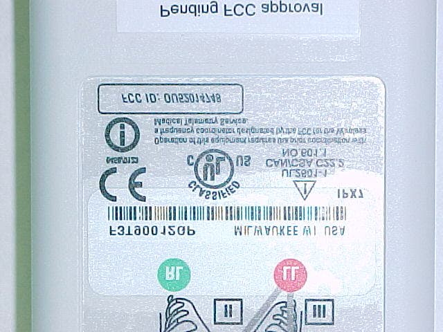
OU52014748
Aug 25, 2003Medical Telemetry Transmitter worn on body
Equipment Class
TNT - Licensed Non-Broadcast Transmitter Worn on Body
OU5340MT
Sep 30, 2002WMTS Transmitter
Equipment Class
TNT - Licensed Non-Broadcast Transmitter Worn on Body