OU52014748Medical Telemetry Transmitter worn on body
GE Medical Systems Information Technologies Inc.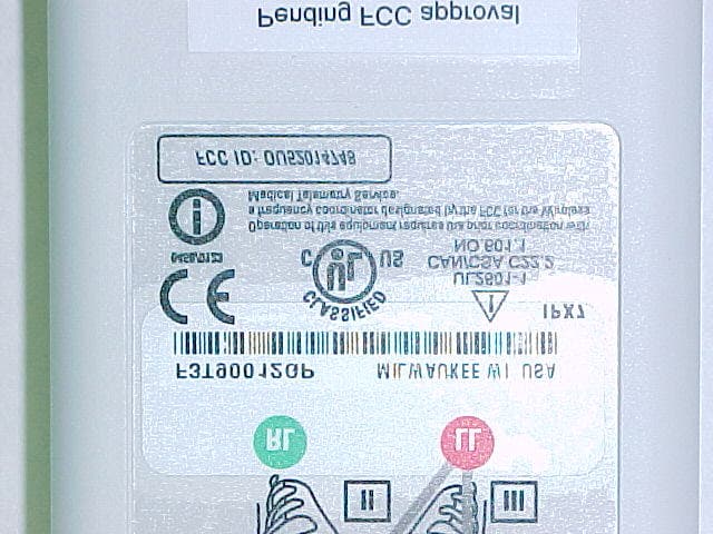
Click to zoom
Application Details
- Equipment Class
- TNT - Licensed Non-Broadcast Transmitter Worn on Body
- Date of Grant
- Aug 25, 2003
- Application Purpose
- Original Equipment
- Date of Application
- Aug 25, 2003
- Equipment Note
- Medical Telemetry Transmitter worn on body
- Frequency Range
- 608.02500000 - 613.97500000
- Country
- United States
Documents & Files
Document Text
Text extracted from the exhibit documents filed with the FCC. Open a document above to read the original.
Users Manual
ApexPro ™ Telemetry System Operator’s Manual Software Version 3 2001989-134Revision B T-2ApexPro Telemetry SystemRevision B 2001989-1341 August 2003 NOTE: The information in this manual only applies to ApexPro Telemetry System software version 3. It does not apply to earlier software versions. Due to continuing product innovation, specifications in this manual are subject to change without notice. Listed below are GE Medical Systems Information Technologies trademarks. All other trademarks contained herein are the property of their respective owners. APEX, ApexPro, DINAMAP Pro, and UNITY NETWORK are trademarks of GE Medical Systems Information Technologies registered in the United States Patent and Trademark Office. CD Telemetry ® -LAN, CIC Pro, IMPACT.wf, PRN 50 are a trademarks of GE Medical Systems Information Technologies. © GE Medical Systems Information Technologies, 2003. All rights reserved.
Users Manual
Revision BApexPro Telemetry Systemi 2001989-134 Contents 1The Basics . . . . . . . . . . . . . . . . . . . . . . . . . . . . . . . . . . . . . 1-1 About This Manual . . . . . . . . . . . . . . . . . . . . . . . . . . . . . . . . . . . . . . . . . . . . . . . . . . . 1-3 Manual Purpose . . . . . . . . . . . . . . . . . . . . . . . . . . . . . . . . . . . . . . . . . . . . . . . . . . . 1-3 Intended Audience . . . . . . . . . . . . . . . . . . . . . . . . . . . . . . . . . . . . . . . . . . . . . . . . . 1-3 Revision History . . . . . . . . . . . . . . . . . . . . . . . . . . . . . . . . . . . . . . . . . . . . . . . . . . . 1-3 Manual Conventions . . . . . . . . . . . . . . . . . . . . . . . . . . . . . . . . . . . . . . . . . . . . . . . . . 1-4 Product References . . . . . . . . . . . . . . . . . . . . . . . . . . . . . . . . . . . . . . . . . . . . . . . . 1-4 Definitions . . . . . . . . . . . . . . . . . . . . . . . . . . . . . . . . . . . . . . . . . . . . . . . . . . . . . . . 1-4 Illustrations and Names . . . . . . . . . . . . . . . . . . . . . . . . . . . . . . . . . . . . . . . . . . . . . 1-5 Common Operations . . . . . . . . . . . . . . . . . . . . . . . . . . . . . . . . . . . . . . . . . . . . . . . . . 1-6 “Clicking” the Mouse . . . . . . . . . . . . . . . . . . . . . . . . . . . . . . . . . . . . . . . . . . . . . . . 1-6 Radio Buttons . . . . . . . . . . . . . . . . . . . . . . . . . . . . . . . . . . . . . . . . . . . . . . . . . . . . 1-6 Check Boxes . . . . . . . . . . . . . . . . . . . . . . . . . . . . . . . . . . . . . . . . . . . . . . . . . . . . . 1-7 Scroll Bars . . . . . . . . . . . . . . . . . . . . . . . . . . . . . . . . . . . . . . . . . . . . . . . . . . . . . . . 1-7 Popup Lists . . . . . . . . . . . . . . . . . . . . . . . . . . . . . . . . . . . . . . . . . . . . . . . . . . . . . . 1-8 Unit Defaults Worksheet . . . . . . . . . . . . . . . . . . . . . . . . . . . . . . . . . . . . . . . . . . . . . . 1-9 Telemetry Alarm Control Defaults . . . . . . . . . . . . . . . . . . . . . . . . . . . . . . . . . . . . . 1-9 Telemetry Unit Defaults . . . . . . . . . . . . . . . . . . . . . . . . . . . . . . . . . . . . . . . . . . . 1-10 2Safety . . . . . . . . . . . . . . . . . . . . . . . . . . . . . . . . . . . . . . . . . 2-1 For Your Safety . . . . . . . . . . . . . . . . . . . . . . . . . . . . . . . . . . . . . . . . . . . . . . . . . . . . . 2-3 Intended Use . . . . . . . . . . . . . . . . . . . . . . . . . . . . . . . . . . . . . . . . . . . . . . . . . . . . . 2-3 Definitions . . . . . . . . . . . . . . . . . . . . . . . . . . . . . . . . . . . . . . . . . . . . . . . . . . . . . . . 2-3 System Safety . . . . . . . . . . . . . . . . . . . . . . . . . . . . . . . . . . . . . . . . . . . . . . . . . . . . 2-4 Reference Literature . . . . . . . . . . . . . . . . . . . . . . . . . . . . . . . . . . . . . . . . . . . . . . 2-12 Classification . . . . . . . . . . . . . . . . . . . . . . . . . . . . . . . . . . . . . . . . . . . . . . . . . . . . 2-13 Underwriters Laboratories, Inc. . . . . . . . . . . . . . . . . . . . . . . . . . . . . . . . . . . . . . . 2-13 FCC Compliance Information Statement . . . . . . . . . . . . . . . . . . . . . . . . . . . . . . . 2-14 Equipment Symbols . . . . . . . . . . . . . . . . . . . . . . . . . . . . . . . . . . . . . . . . . . . . . . . 2-15 iiApexPro Telemetry SystemRevision B 2001989-134 3Equipment Overview . . . . . . . . . . . . . . . . . . . . . . . . . . . . . 3-1 Introduction . . . . . . . . . . . . . . . . . . . . . . . . . . . . . . . . . . . . . . . . . . . . . . . . . . . . . . . . 3-3 ApexPro Telemetry System . . . . . . . . . . . . . . . . . . . . . . . . . . . . . . . . . . . . . . . . . . . 3-4 Compatibility with Bedside Monitors . . . . . . . . . . . . . . . . . . . . . . . . . . . . . . . . . . . 3-5 ApexPro Transmitters . . . . . . . . . . . . . . . . . . . . . . . . . . . . . . . . . . . . . . . . . . . . . . 3-6 ApexPro CH Transmitter . . . . . . . . . . . . . . . . . . . . . . . . . . . . . . . . . . . . . . . . . . . 3-10 ApexPro FH Transceiver . . . . . . . . . . . . . . . . . . . . . . . . . . . . . . . . . . . . . . . . . . . 3-11 Apex Oximeter SpO2 Module . . . . . . . . . . . . . . . . . . . . . . . . . . . . . . . . . . . . . . . 3-12 Xpod™ Oximeter . . . . . . . . . . . . . . . . . . . . . . . . . . . . . . . . . . . . . . . . . . . . . . . . . 3-13 Accutracker DX Noninvasive Blood Pressure (NBP) Monitor . . . . . . . . . . . . . . . 3-14 DINAMAP® PRO Series Monitors . . . . . . . . . . . . . . . . . . . . . . . . . . . . . . . . . . . . 3-16 Antenna System . . . . . . . . . . . . . . . . . . . . . . . . . . . . . . . . . . . . . . . . . . . . . . . . . . 3-17 Receiver System . . . . . . . . . . . . . . . . . . . . . . . . . . . . . . . . . . . . . . . . . . . . . . . . . 3-17 Unity Network . . . . . . . . . . . . . . . . . . . . . . . . . . . . . . . . . . . . . . . . . . . . . . . . . . . . 3-17 CIC Pro Clinical Information Center . . . . . . . . . . . . . . . . . . . . . . . . . . . . . . . . . . . 3-18 4Connection . . . . . . . . . . . . . . . . . . . . . . . . . . . . . . . . . . . . 4-1 ApexPro Transmitter Setup . . . . . . . . . . . . . . . . . . . . . . . . . . . . . . . . . . . . . . . . . . . 4-3 ApexPro Transmitter Battery Installation . . . . . . . . . . . . . . . . . . . . . . . . . . . . . . . . 4-3 Battery Functional Life . . . . . . . . . . . . . . . . . . . . . . . . . . . . . . . . . . . . . . . . . . . . . . 4-4 ApexPro Transmitter Leadwires . . . . . . . . . . . . . . . . . . . . . . . . . . . . . . . . . . . . . . . 4-5 Apex Oximeter Setup . . . . . . . . . . . . . . . . . . . . . . . . . . . . . . . . . . . . . . . . . . . . . . . . 4-7 Apex Oximeter Battery Installation . . . . . . . . . . . . . . . . . . . . . . . . . . . . . . . . . . . . . 4-7 Battery Functional Life . . . . . . . . . . . . . . . . . . . . . . . . . . . . . . . . . . . . . . . . . . . . . . 4-7 Apex Oxime…
Text truncated - open the document above for the full version.
Users Manual
Revision BApexPro Telemetry System2-1 2001989-134 2Safety 2-2ApexPro Telemetry SystemRevision B 2001989-134 For your notes Revision BApexPro Telemetry System2-3 2001989-134 Safety: For Your Safety For Your Safety Intended Use The ApexPro Telemetry System is intended for use under the direct supervision of a licensed healthcare practitioner. The system is designed to acquire and monitor physiological data for ambulating patients within a defined coverage area. The system processes this physiological data to detect various ECG arrhythmia events and select physiological parameter limit violations. The ApexPro Telemetry System is intended to be installed in the hospital or clinical environment in order to provide clinicians with patient physiological data, while allowing for patient mobility. These systems are typically deployed in sub acute care areas in hospitals or clinical sites where patient mobility can enhance the effectiveness of the medical procedures administered. The physiological parameters monitored include ECG, non-invasive blood pressure and SpO2. The ApexPro Telemetry System is intended to provide ECG data via Ethernet to the computer platform for processing. The ApexPro is also intended to provide physiologic data over the Unity network to clinical information systems for display. Definitions The terms danger, warning, and caution are used throughout this manual to point out hazards and to designate a degree or level or seriousness. Familiarize yourself with their definitions and significance. Hazard is defined as a source of potential injury to a person. DANGER indicates an imminent hazard which, if not avoided, will result in death or serious injury. WARNING indicates a potential hazard or unsafe practice which, if not avoided, could result in death or serious injury. CAUTION indicates a potential hazard or unsafe practice which, if not avoided, could result in minor personal injury or product/property damage. NOTE provides application tips or other useful information to assure that you get the most from your equipment. 2-4ApexPro Telemetry SystemRevision B 2001989-134 Safety: For Your Safety System Safety The safety statements presented in this chapter refer to the equipment in general and, in most cases, apply to all aspects of the telemetry system. There are additional safety statements in other chapters that are specific to the information presented in that chapter. The order in which safety statements are presented in no way implies order of importance. Dangers There are no dangers that refer to the equipment in general. Specific “Danger” statements may be given in the respective sections of this manual. Warnings WARNINGS ACCIDENTAL SPILLS — To avoid electric shock or device malfunction liquids must not be allowed to enter the device. If liquids have entered a device, take it out of service and have it checked by a service technician before it is used again. ACCURACY — If the accuracy of any value displayed on the monitor, central station, or printed on a graph strip is questionable, determine the patient's vital signs by alternative means. Verify that all equipment is working correctly. Revision BApexPro Telemetry System2-5 2001989-134 Safety: For Your Safety WARNINGS ALARMS — Do not rely exclusively on the audible alarm system for patient monitoring. Adjustment of alarm volume to a low level or off during patient monitoring may result in a hazard to the patient. Do not rely exclusively on the alarm pause breakthrough feature for alarm notification during an alarm pause. This may result in a hazard to the patient. Only crisis alarms break through an alarm pause. Remember that the most reliable method of patient monitoring combines close personal surveillance with correct operation of monitoring equipment. After connecting the monitor to the central station, nurse alert system, and/or network, verify the function of the alarm system. The functions of the alarm system for monitoring of the patient must be verified at regular intervals. BEFORE USE — Before putting the system into operation visually inspect all connecting cables for signs of damage. Damaged cables and connectors must be replaced immediately. Before using the system, the operator must verify that it is in correct working order and operating condition. Periodically, and whenever the integrity of the product is in doubt, test all functions. CABLES — Route all cables away from patient's throat to avoid possible strangulation. 2-6ApexPro Telemetry SystemRevision B 2001989-134 Safety: For Your Safety WARNINGS CONDUCTIVE CONNECTIONS — Extreme care must be exercised when applying medical electrical equipment. Many parts of the human/machine circuit are conductive, such as the patient, connectors, electrodes, transducers. It is very important that these conductive parts do not come into contact with other grounded, conductive parts when connected to the isolated patient input of the device. Such contact would bridge the patient's isolation and cancel the protection provided by the isolated input. In particular, there must be no contact of the neutral electrode and ground. DEFIBRILLATION — Do not come into contact with patients during defibrillation. Otherwise serious injury or death could result. DISCONNECTION FROM MAINS — When disconnecting the system from the power line, remove the plug from the wall outlet first. Then you may disconnect the power cord from the device. If you do not observe this sequence, there is a risk of coming into contact with line voltage by inserting metal objects, such as the pins of leadwires, into the sockets of the power cord by mistake. DISPOSAL — Dispose of the packaging material, observing the applicable waste control regulations and keeping it out of children's reach. EXPLOSION HAZARD — Do not use this equipment in the presence of flammable anesthetics, vapors or liquids. INTERFACING OTHER EQUIPMENT — Devices may only be interconnected with each other or to parts of the system wh…
Text truncated - open the document above for the full version.
Users Manual
GE Medical Systems Information Technologie s g gemedical.com APEX , ApexPro and ApexPro CH Transmitter Programming Instructions Software Version 2 2001989-135 Revision A - Draft 7 D r a f t T-2APEX‚ and ApexPro‘ Transmitter Programming InstructionsRevision A - Draft 7 2001989-1358/5/03 NOTE: NOTE: NOTE: NOTE: The information in this manual only applies to APEX, ApexPro, and ApexPro CH Transmitter Programming Instructions software version 1. It does not apply to earlier software versions. Due to continuing product innovation, specifications in this manual are subject to change without notice. Listed below are GE Medical Systems Information Technologies trademarks used in this manual. All other trademarks contained herein are the property of their respective owners. U NITY NETWORK, ApexPro, CD TELEMETRY, TRAMSCOPE, EAGLE, SOLAR, DASH, MARS, and RSVP are trademarks of GE Medical Systems Information Technologies registered in the United States Patent and Trademark Office. CD TELEMETRY ® –LAN, CENTRALSCOPE, ICMMS, Octacomm, and Octanet are trademarks of GE Medical Systems Information Technologies. © GE Medical Systems Information Technologies, 2000-2003. All rights reserved. D r a f t Revision A- Draft 6APEX and ApexPro Transmitter Programming Instructionsiii 2001989-135 Contents 1Introduction . . . . . . . . . . . . . . . . . . . . . . . . . . . . . . . . . . . . . . 7 Overview . . . . . . . . . . . . . . . . . . . . . . . . . . . . . . . . . . . . . . . . . . . . . . . . . . . . . . . . . . . . . 8 Standards Used in this Manual . . . . . . . . . . . . . . . . . . . . . . . . . . . . . . . . . . . . . . . . 8 Definitions . . . . . . . . . . . . . . . . . . . . . . . . . . . . . . . . . . . . . . . . . . . . . . . . . . . . 8 Illustrations and Names . . . . . . . . . . . . . . . . . . . . . . . . . . . . . . . . . . . . . . . . . . 8 Document Revision History . . . . . . . . . . . . . . . . . . . . . . . . . . . . . . . . . . . . . . . . . . . 8 Install the Programming Device . . . . . . . . . . . . . . . . . . . . . . . . . . . . . . . . . . . . . . . . . . 9 Hardware Requirements for the Programming Device . . . . . . . . . . . . . . . . . . . . . . 9 Install the Software . . . . . . . . . . . . . . . . . . . . . . . . . . . . . . . . . . . . . . . . . . . . . . . . 10 Remove the Previous Version of Software . . . . . . . . . . . . . . . . . . . . . . . . . . 10 Run the Installation Wizard . . . . . . . . . . . . . . . . . . . . . . . . . . . . . . . . . . . . . . 11 Connect the Hardware . . . . . . . . . . . . . . . . . . . . . . . . . . . . . . . . . . . . . . . . . . . . . . 11 Disconnect the Hardware . . . . . . . . . . . . . . . . . . . . . . . . . . . . . . . . . . . . . . . . . . . . 12 Run the Apex & ApexPro Programming Box Software . . . . . . . . . . . . . . . . . . . . . . 13 Start the Software . . . . . . . . . . . . . . . . . . . . . . . . . . . . . . . . . . . . . . . . . . . . . . . . . 13 Select the Transmitter . . . . . . . . . . . . . . . . . . . . . . . . . . . . . . . . . . . . . . . . . . . . . . 13 Select a Hospital . . . . . . . . . . . . . . . . . . . . . . . . . . . . . . . . . . . . . . . . . . . . . . . . . . 14 Generate Reports . . . . . . . . . . . . . . . . . . . . . . . . . . . . . . . . . . . . . . . . . . . . . . . . . 15 Excel Report . . . . . . . . . . . . . . . . . . . . . . . . . . . . . . . . . . . . . . . . . . . . . . . . . 15 Log Report . . . . . . . . . . . . . . . . . . . . . . . . . . . . . . . . . . . . . . . . . . . . . . . . . . . 17 Apex and ApexPro Transmitter Programming Instructions Manual . . . . . . . . 18 Flyover Windows . . . . . . . . . . . . . . . . . . . . . . . . . . . . . . . . . . . . . . . . . . . . . . 18 About the Apex Program . . . . . . . . . . . . . . . . . . . . . . . . . . . . . . . . . . . . . . . . 18 Program Other Transmitters . . . . . . . . . . . . . . . . . . . . . . . . . . . . . . . . . . . . . . . . . . . . 19 2Apex Transmitter . . . . . . . . . . . . . . . . . . . . . . . . . . . . . . . . . 21 Program the Transmitter’s Basic Functions . . . . . . . . . . . . . . . . . . . . . . . . . . . . . . . 23 The Main Programming Window . . . . . . . . . . . . . . . . . . . . . . . . . . . . . . . . . . . . . . 23 Message Area . . . . . . . . . . . . . . . . . . . . . . . . . . . . . . . . . . . . . . . . . . . . . . . . . . . . 23 TTX Number and Frequency Settings . . . . . . . . . . . . . . . . . . . . . . . . . . . . . . . . . . 23 Band Setting . . . . . . . . . . . . . . . . . . . . . . . . . . . . . . . . . . . . . . . . . . . . . . . . . . . . . 24 Reference Lead Setting . . . . . . . . . . . . . . . . . . . . . . . . . . . . . . . . . . . . . . . . . . . . . 25 For 5- or 6-Lead Cables . . . . . . . . . . . . . . . . . . . . . . . . . . . . . . . . . . . . . . . . . 25 For 3-Lead Cables . . . . . . . . . . . . . . . . . . . . . . . . . . . . . . . . . . . . . . . . . . . . . 25 Alarm Pause Setting . . . . . . . . . . . . . . . . . . . . . . . . . . . . . . . . . . . . . . . . . . . . . . . 26 Firmware Code Revision Number . . . . . . . . . . . . . . . . . . . . . . . . . . . . . . . . . . . . . 26 Exit Button . . . . . . . . . . . . . . . . . . . . . . . . . . . . . . . . . . . . . . . . . . . . . . . . . . . . . . . 26 D r a f t ivAPEX and ApexPro Transmitter Programming InstructionsRevision A- Draft 6 2001989-135 Perform Advanced Functions . . . . . . . . . . . . . . . . . . . . . . . . . . . . . . . . . . . . . . . . . . . 27 Perform Advanced Programming . . . . . . . . . . . . . . . . . . . . . . . . . . . . . . . . . . . . . . 27 Communication Status Button . . . . . . . . . . . . . . . . . . . . . . . . . . . . . . . . . . . . 27 Set Serial Number . . . . . . . . . . . . . . . . . . . . . . . . . . . . . . . . . . . . . . . . . . . . . 27 Change Alarm Pause Setting . . . . . . . . . . . . . . . . . . . . . . . . . . . . . . . . . . . . . 27 Monitor the Status of Transmitter Tests . . . . . . . . . . . . .…
Text truncated - open the document above for the full version.
Cover Letter(s)
TCB SAR Questions 1. Please justify how the system validation target SAR value of 2.375mW/g obtained. Please see the response attached 2. The liquid temperature during SAR test and validation exceeded +/-2C of tissue verification liquid temperature of 23.5C. Please justify how this tissue simulating liquid maintained the same dielectric parameters as listed. Please see the response attached. Curtis-Straus Response: We did not agree with the liquid temperature justification provided but we have decided to proceed with this report as is. 3. 15cm liquid depth can not be easily determined from the test setup pictures. Please show/justify how this liquid depth meets 15cm minimum limit. Please see the response attached. 4. Please specify the grid sizes used in coarse and zoom scans. Please see the response attached 5. What was the probe tip distance to phantom inner surface during coarse-scan? Please see the response attached 6. Please provide more specific details of 1gram averaging method. Please see the response attached
Cover Letter(s)
Page 1 of 2 Answers for Curtis-Straus Re: SAR.230625305.OU5 SAR Report Prepared By PCTEST Engineering Laboratory, Inc. 1. The target system verification target SAR value was obtained by multiplying the 1W target of 9.5 W/kg (IEEE Std P1528 Draft 6.5 Table 7.1) by the actual input power of 0.250W. Thus, the target SAR value for the system at 0.250W is: 9.5 * 0.250 = 2.375 W/kg. 2. The liquid for system verification was brain-simulating liquid (per Supplement C), whereas the muscle simulating liquid (a different tissue material) was used to assess the Body SAR for the device. 3. Please find attached photographs with measurements indicating a liquid depth of at least 15 cm in the phantom shell. 4. The Area scan is a single layer scan done at 2.5 mm above the phantom surface. The grid data is run in 10x10mm increments and cover the whole DUT. A splined is run on the data at 1mm increments. This is used to determine the local hot spot. The zoom scan is centered on this hot spot. The zoom scan is a cube scan of size 7x7x7 points at spacing 5x5x5mm for a cube size of 30x30x30mm. 5. The probe tip distance to phantom inner surface during coarse-scan is 2.5mm (less than half the probe tip diameter). Page 2 of 2 6. The points are extrapolated to the surface using a 4 th order Lagrange polynomial. A 3D spline is run over all sampled and extrapolated points to get points spaced 1 mm apart in all directions. For the 1-gram average, the software then calculates all the 10x10x10mm averages. It then finds the greatest value and reports it. SAR Calculation: Each SAR point was found using: Sum = ((Ch1Ave * Gain)/Sense1 + (Ch2Ave * Gain)/Sense2 + (Ch3Ave * Gain)/Sense) Sense1-3 = Sensitivity of probe mv/(mW/cm^2) Ch#Ave = Average reading from the Probe Channel Gain = DC Amplifier Gain (Around 20x) SAR = (Sum * σ * 3770) / (ρ * CF) Sum = Sum of 3 channels (from above) (mW/cm^2) σ = Conductivity ρ = Tissue Density (usually 1.0 during scan) CF = Conversion Factor
Cover Letter(s)
Response to TCB Questions The frequency stability test has been conducted between 0 and 50 degrees C temperatures. We would like to know the manufacturers specified operating temperature range Response: Environmental Specifications for the ApexPro CH transmitter: Operating conditions Ambient temperature: 0C to 50C (32F to 122F) Relative humidity: 5% to 95% (non-condensing) Storage conditions Temperature: -40C to 70C (-40F to 158F) Relative humidity: 30% to 95% (non-condensing) Pressure: 700 hPa to 1060 hPa
External Photos
General Electric Medical Systems Ambulatory Patient Monitor 608.025 – 613.975 MHz Digital Radio FCC ID#: OU52014748 Photo One – External ApexPro CH Front View with Patient Connecting Cable General Electric Medical Systems Ambulatory Patient Monitor 608.025 – 613.975 MHz Digital Radio FCC ID#: OU52014748 Photo Two – External ApexPro CH Back View showing location of FCC ID Label General Electric Medical Systems Ambulatory Patient Monitor 608.025 – 613.975 MHz Digital Radio FCC ID#: OU52014748 Photo Three – External ApexPro CH FCC ID Label. General Electric Medical Systems Ambulatory Patient Monitor 608.025 – 613.975 MHz Digital Radio FCC ID#: OU52014748 Photo Four – External ApexPro CH Close-Up of FCC ID Label. General Electric Medical Systems Ambulatory Patient Monitor 608.025 – 613.975 MHz Digital Radio FCC ID#: OU52014748 Photo Five – External ApexPro CH Battery Compartment with Batteries General Electric Medical Systems Ambulatory Patient Monitor 608.025 – 613.975 MHz Digital Radio FCC ID#: OU52014748 Photo Six – External ApexPro CH View showing Patient Cable Connection
Internal Photos
General Electric Medical Systems Ambulatory Patient Monitor 608.025 – 613.975 MHz Digital Radio FCC ID#: OU52014748 Photo One – Internal ApexPro CH Open for Inspection General Electric Medical Systems Ambulatory Patient Monitor 608.025 – 613.975 MHz Digital Radio FCC ID#: OU52014748 Photo Two – Internal ApexPro CH Digital PCB Component Side General Electric Medical Systems Ambulatory Patient Monitor 608.025 – 613.975 MHz Digital Radio FCC ID#: OU52014748 Photo Three – Internal ApexPro CH Digital PCB – RF Side, RF Section Shielded General Electric Medical Systems Ambulatory Patient Monitor 608.025 – 613.975 MHz Digital Radio FCC ID#: OU52014748 Photo Four – Internal ApexPro CH RF Section with Shielding Removed General Electric Medical Systems Ambulatory Patient Monitor 608.025 – 613.975 MHz Digital Radio FCC ID#: OU52014748 Photo Five – Internal ApexPro CH RF Section with Additional Shielding Removed General Electric Medical Systems Ambulatory Patient Monitor 608.025 – 613.975 MHz Digital Radio FCC ID#: OU52014748 Photo Six – Internal ApexPro CH Un Shielded side of RF Section
Test Report
L.S. Compliance, Inc. W66 N220 Commerce Court Cedarburg, WI 53012 262-375-4400 Fax: 262-375-4248 COMPLIANCE TESTING OF: Apex Pro CH PREPARED FOR: GE Medical Systems Information Technologies 8200 Tower Avenue Milwaukee, WI 53223 TEST REPORT NUMBER: 303299 Rev. 1 TEST DATE(S): June 26, 2003 All results of this report relate only to the items that were tested. This report is not to be reproduced, except in full, without written approval of L. S. Compliance, Inc. L.S. Compliance, Inc. Page 2 of 26 Test Report Number: 303299 Rev. 1 Prepared For: GE Medical Systems Information Technologies Table of Contents Section Description Test Type Page Index 2 1 L. S. Compliance in Review 3 2 A2LA Certificate of Accreditation 4 3 A2LA Scope of Accreditation 5 4 Validation Letter-U.S. Competent Body for EMC Directive 89/336/EEC 6 5 Signature Page 7 6 Product and General Information 8 7 Product Description 8 8 Test Requirements 8 9 Summary of Test Report 9 10 Introduction 9 11 Purpose 9 12 Radiated Emissions Test FCC Part 95.1115 10-15 13 Conducted Emissions Test (AC Line) FCC Part 15.207 19 14 Conducted Emissions Test, power output FCC Part 2.1046 20-21 15 Conducted Emissions Test, spurious emissions FCC Part 2.1053 22 16 Conducted Emissions Test, occupied bandwidth FCC Part 2.1049 23 17 Conducted Emissions Test, Frequency Stability FCC Part 2.1055 24 Appendix A Test Equipment List 25 L.S. Compliance, Inc. Page 3 of 26 Test Report Number: 303299 Rev. 1 Prepared For: GE Medical Systems Information Technologies 1. L. S. Compliance In Review L. S. Compliance, Inc. is located in Cedarburg, Wisconsin – United States. We may be contacted by: Mail: L. S. Compliance, Inc. W66 N220 Commerce Court Cedarburg, Wisconsin 53012 Phone: 262-375-4400 Fax: 262-375-4248 E-mail: [email protected] As an EMC Testing Laboratory, our Accreditation and Assessments are recognized through the following: A2LA – American Association for Laboratory Accreditation Accreditation based on ISO/IEC 17025 : 2001 with Electrical (EMC) Scope of Accreditation A2LA Certificate Number: 1255.01 U. S. Conformity Assessment Body (CAB) Validation Validated by the European Commission as a U. S. Conformity Assessment Body operating under the U. S. /EU, Mutual Recognition Agreement (MRA) operating under the European Union EMC Directive 89/336/EEC, Article 10.2. Date of Validation: January 16, 2001 Federal Communications Commission (FCC) – USA Listing of 3 Meter Semi-Anechoic Chamber based on 47CFR 2.948 FCC Registration Number: 90756 Listing of 3 and 10 meter OATS based on 47CFR 2.948 FCC Registration Number: 90757 Industry Canada On-file, 3 Meter Semi-Anechoic Chamber based on 47CFR 2.948 File Number: IC 3088 On-file 3 and 10 Meter OATS based on RSS-210 File Number: IC 3088-A L.S. Compliance, Inc. Page 4 of 26 Test Report Number: 303299 Rev. 1 Prepared For: GE Medical Systems Information Technologies 2. A2LA Certificate of Accreditation L.S. Compliance, Inc. Page 5 of 26 Test Report Number: 303299 Rev. 1 Prepared For: GE Medical Systems Information Technologies 3. A2LA Scope of Accreditation L.S. Compliance, Inc. Page 6 of 26 Test Report Number: 303299 Rev. 1 Prepared For: GE Medical Systems Information Technologies 4. Validation Letter – U.S. Competent Body for EMC Directive 89/336/EEC L.S. Compliance, Inc. Page 7 of 26 Test Report Number: 303299 Rev. 1 Prepared For: GE Medical Systems Information Technologies 5. Signature Page Prepared By: August 4, 2003 Teresa A. White, Document Coordinator Date Tested By: August 4, 2003 Abtin Spantman, EMC Engineer Date Approved By: August 4, 2003 Kenneth L. Boston, EMC Lab Manager Date PE #31926 Licensed Professional Engineer Registered in the State of Wisconsin, United States L.S. Compliance, Inc. Page 8 of 26 Test Report Number: 303299 Rev. 1 Prepared For: GE Medical Systems Information Technologies 6. Product and General Information Manufacturer: GE Medical Systems Information Technologies Date(s) of Test: June 26 th , 2003 Test Engineer: Abtin Spantman Model #: 2014748 Serial #: Engineering Unit Operating Mode: Continuous transmit, with modulation. 7. Product Description (including type of emission) The ApexPro CH is a telemetry transmitter used in hospitals. The transmitter acquires ECG information and digitizes it for transmission to the antenna system. The transmitter can also transmit information coming from external SpO2 or NIBP devices. The ApexPro CH is designed to operate on 239 channels, at carrier frequencies between 608 and 614 MHz, with a GFSK modulation format. The ApexPro CH operates on two type AA batteries for a series voltage of 3.0 VDC, and utilizes an external antenna embedded into the patient lead wires. 8. Test Requirements The above-mentioned tests were performed in order to determine the compliance of the ApexPro CH with limits contained in various provisions of Title 47 CFR, FCC Part 95H, including: 2.1046, 2.1049, 2.1051, 2.1053, 2.1055, 15.207 and 95.1115. All radiated emissions tests were performed to measure the emissions in the frequency bands described by the above sections, and to determine whether said emissions are below the limits established by the above sections. These tests were performed in accordance with the procedure described in the American National Standard for methods of measurement of Radio-Noise Emissions from Low-Voltage Electrical and Electronic Equipment in the Range of…
Text truncated - open the document above for the full version.
Contact Information
Applicant
Matthew R Pekarske(Principal of Connectivity and Service Technology)
Test Firm
LS Research, LLCRyan Urness
Technical Specifications
| # | Rule Parts | Frequency Range | Power Output | Emission | Tolerance |
|---|---|---|---|---|---|
| 1 | 95H | 608.025 MHz - 613.975 MHz | 600.00 µW | 9K70F1D | 1.3000000000 ppm |
Other Applications from GE Medical Systems Information Technologies Inc.

OU5-5406102
Jan 10, 2011URP Detector UWB Radio PWA and Antenna Module
Equipment Class
UWB - Ultra Wideband Transmitter
OU507APFH-AP
Dec 18, 2007Wireless Access Point (AP) for Medical Monitoring
Equipment Class
TNB - Licensed Non-Broadcast Station Transmitter
OU52014748-002
Dec 18, 2007Medical Telemetry Transmitter
Equipment Class
TNT - Licensed Non-Broadcast Transmitter Worn on Body
OU5SHU-WMTS
Sep 09, 2007EA-WMTS-SHU-4
Equipment Class
TNB - Licensed Non-Broadcast Station Transmitter
OU5340MT
Sep 30, 2002WMTS Transmitter
Equipment Class
TNT - Licensed Non-Broadcast Transmitter Worn on Body