OU9GKS1136BTBluetooth Kitchen Scale
Guangdong Transtek Medical Electronics Co.,Ltd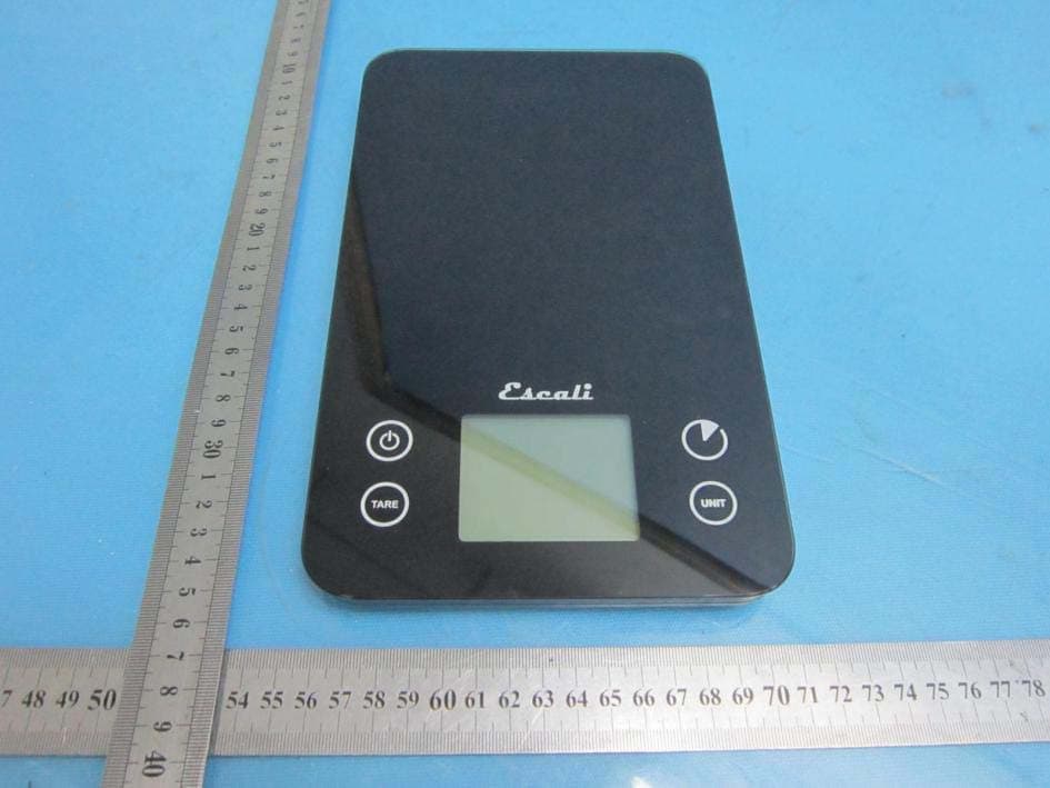
Click to zoom
Application Details
- Equipment Class
- DTS - Digital Transmission System
- Date of Grant
- Sep 15, 2013
- Application Purpose
- Original Equipment
- Date of Application
- Sep 15, 2013
- Equipment Note
- Bluetooth Kitchen Scale
- Frequency Range
- 2402.00000000 - 2480.00000000
- Country
- China
Documents & Files
Document Text
Text extracted from the exhibit documents filed with the FCC. Open a document above to read the original.
Users Manual
version:1.0 GUANGDONG TRANSTEK MEDICAL ELECTRONICS CO., LTD Zone A, 5/F., Investment Building, No. 12, Huizhan East Rd., Torch Development District, Zhongshan, Guangdong, 528437, China TEL:86-760-88282982 www.transtek.cn User Manual Kitchen ScaleGKS-1136-BT Please do read the user manual carefully and thoroughly so as to ensure the safe usage of this product, and keep the manual well for further reference in case you have problems. Thank you very much for selecting the Transtek Kitchen Scale GKS-1136-BT. 1 Table of Contents Table of Contents Initial Setup Pairing with the App Symbol Meaning Weight Measurements Kitchen Timer Bluetooth Smart 2 2 2 3 4 4 ................................................................................................................. ................................................................................................................. ................................................................................................................... .......................................................................................................... .................................................................................................................... ............................................................................................................... . Tare (Add & Weigh) 3 ............................................................................................................... 4 .................................................................................................................... Touch Sensitive Controls 4 .................................................................................................... Automatic Shut-off Blue Backlight Display ............................................................................................................... .................................................................................................................... Sounds ........................................................................................................................ Proper Use & Care Warning Messages ................................................................................................................... .................................................................................................................... Product Specifications .................................................................................................... Maintenance ................................................................................................................... Warranty 5 5 5 6 6 7 7 23 Weight Measurements Initial Setup 1. Remove batteries from plastic wrap and insert them into the battery compartment located beneath the scale. 2. Download the free Escali SmartConnect app from the Apple App Store. 3. Remove the app reminder cling from the scale & wipe clean. Pairing with the App 1. Turn on bluetooth for your iPhone or iPad. 2. Install and open the App. 3. Create a profile (optional ) or select “USE AS A GUEST”. 4. Navigate to the KITCHEN screen. 5. Press the Bluetooth button and the symbol will turn blue. 6. Turn on the Kitchen Scale. Hardware requirements: iPhone 4s (or newer), iPad 3rd generation (or newer), iPad Mini (or newer), iPod Touch 5th generation(or newer) Software requirements: iOS 6.0 (or newer) Attention! Open the app before turning on the kitchen scale for successful pairing. If you have troubles pairing the scale with the app turn off the scale, completely close the app and start over at step 1. 1. Press the power to turn the scale on. 2. Press UNIT to change units(pounds, ounces, grams.) 3. Place an item on the scale in the center of the platform. Ignore the weight of a container: 1. Place a container on the platform before turning the scale on. -OR- 1. Turn the scale on, add the container and press TARE 2. Wait 3 seconds and zero weight will display. 3. Add items into the container to be weighed. Find the individual weight of multiple items in one container: 1. Press TARE to reset the scale back to zero weight. 2. Add additional items to be weighed. 3. Repeat steps 1-2 for each additional item. Reset the scale back to zero weight: 1. If nothing is on the scale and it does not read zero weight, press TARE to reset the scale back to zero weight. Tare (Add & Weigh) Attention! The scale will tare any amount of weight. Once the total weight actually on the scale reaches the maximum capacity of 11 pounds( 5000 g.) the overload warning code (EEEE) will display. [ ] [ ] [ ] [ ] [ ] [ ] The warning signs and symbols are essential to ensure your correct and safe use of this product and protect you and others from injury. Please kindly find the meanings of the warning signs and symbols, which you may encounter in the label and user manual, as follows: Symbol Meaning Symbol for “THE OPERATION GUIDE MUST BE READ” Symbol for “COMPLIES WITH MDD 93/42/ECC REQUIREMENTS” Symbol for “ENVIRONMENT PROTECTION – Waste electrical products should not be disposed of with household waste. Please recycle where facilities exist. Check with your local authority or retailer for recycling advice” The Bluetooth Combination Mark Symbol for “SERIAL NUMBER” 5 4 Kitchen Timer 1. Press the timer symbol to enter into the timer feature. 2. Press UNIT to change numbers. Press to confirm. 3. After selecting the last number, press to start the timer. 4. Press to switch back into scale mode. The timer will continue to run. Press to switch back into timer mode. 5. To reset the timer, press and hold while in timer mode. 6. Press to turn off the alarm. Bluetooth Smart wireless technology allows for the Transtek Kitchen Scale to automatically send weight measurements to your iPhone or iPad for enhance functionality. Download the app from the APP Store. Bluetooth Smart * The controls are touch sensitive. * Light contact with the surface of the controls will activate them. * Pressing ha…
Text truncated - open the document above for the full version.
External Photos
EXTERNALPHOTOGRAPHSOFEUT View of Product-1 View of Product-2 View of Product-3 View of Product-4
ID Label/Location Info
Label location
Internal Photos
INTERNAL PHOTOGRAPHS OF EUT View of Product-1 View of Product-2 View of Product-3 View of Product-4 View of Product-5 View of Product-6 View of Product-7(Bluetooth Module) View of Product-8(Bluetooth Module)
RF Exposure Info
RF Exposures Evaluation For Maximum Permissible Exposure (MPE) evaluation of the product, the maximum power density at 20 cm from this transmitter shall be less than the General Population / Uncontrolled MPE limit in OET Bulletin 65. For the EUT of tested model GKS-1136-BT, the measured maximum field strength measured (FS) was 97.65 dBμV/m. The distance (D) between the antenna and the equipment under test (EUT) was 3 meters. From these data, the exposed power density at a distance (R) of 20cm from the center of radiation of the antenna can be calculated according to OET Bulletin 65 as follow: The radiated power = (FS*D) 2 /30 = 1.746mW The power density at 20 cm from the antenna =EIRP/ = 0.0003475 mW cm -2 In the frequency range of 2.4-2.4835GHz, the MPE limit is 1.0 mWcm -2 for general population and uncontrolled exposure. As the measured power density at 20cm from the transmitter is lower than the MPE limit, the compliance to the MPE limit can be ensured by indicating the minimum 20cm separation betweenthe transmitter's radiating structures and body of the user or nearby persons. The following RF exposure statement is proposed to be included in the user manual: “This equipment complies with FCC RF radiation exposure limits set forth for an uncontrolled environment. This equipment should be installed and operated with a minimum distance of 20 centimeters between the radiator and your body.”
Test Report
Report No.: EESZF08280010 Page 1 of 28 FCC TEST REPORT Product Name : Bluetooth Kitchen Scale Trade Name : N/A Model/Type reference : GKS-1136-BT Serial Number : N/A Ratings : DC 4.5V FCC ID : OU9GKS1136BT Report Number : EESZF08280010 Date : Sep. 09, 2013 Regulations : See below Test Standards Results 47 CFR FCC Part 15 Subpart C 15.247:2012 PASS Prepared by: Guangdong Transtek Medical Electronics Co., Ltd Zone A, 5/F., Investment Building No. 12 Huizhan East Rd., Torch Develop, Guangdong Prepared by: Centre Testing International (Shenzhen) Corporation Hongwei Industrial Zone, 70 Area, Bao’an District, Shenzhen, Guangdong, China TEL: +86-755-3368 3666 FAX: +86-755-3368 3385 Tested by: Reviewed by: Approved by: Date: Sep. 09, 2013 Jimmy Li Lab manager Check No.: 1022591449 Report No.: EESZF07110007-1 Page 2 of 28 TABLE OF CONTENTS 1. GENERAL INFORMATION ............................................................................................. 3 2. PRODUCT INFORMATION ............................................................................................. 4 3. TEST SUMMARY ............................................................................................................ 5 4. MEASUREMENT UNCERTAINTY .................................................................................. 5 5. FACILITIES AND ACCREDITATIONS ............................................................................. 5 5.1 TEST FACILITY ........................................................................................................................................ 5 5.2 TEST EQUIPMENT LIST .......................................................................................................................... 5 5.3 LABORATORY ACCREDITATIONS AND LISTINGS .............................................................................. 6 6. SUPPORT EQUIPMENT ................................................................................................. 6 7. 6DB BANDWIDTH MEASUREMENT .............................................................................. 7 7.1. LIMITS ..................................................................................................................................................... 7 7.2. BLOCK DIAGRAM OF TEST SETUP ..................................................................................................... 7 7.3. TEST PROCEDURE ............................................................................................................................... 7 7.4. TEST RESULT ........................................................................................................................................ 7 8. POWER SPECTRAL DENSITY MEASUREMENT .......................................................... 9 8.1. LIMITS ..................................................................................................................................................... 9 8.2. BLOCK DIAGRAM OF TEST SETUP ..................................................................................................... 9 8.3. TEST PROCEDURE ............................................................................................................................... 9 8.4. TEST RESULT ........................................................................................................................................ 9 9. MAXIMUM PEAK CONDUCTED OUTPUT POWER MEASUREMENT ....................... 11 9.1. LIMITS ................................................................................................................................................... 11 9.2. BLOCK DIAGRAM OF TEST SETUP ................................................................................................... 11 9.3. TEST PROCEDURE ............................................................................................................................. 11 9.4. TEST RESULT ...................................................................................................................................... 11 10. BANDEDGE EMISSION MEASUREMENT ................................................................. 12 10.1. LIMITS ................................................................................................................................................. 12 10.2. BLOCK DIAGRAM OF TEST SETUP ................................................................................................. 12 10.3. TEST PROCEDURE ........................................................................................................................... 12 10.4. TEST RESULT .................................................................................................................................... 13 11. SPURIOUS RF CONDUCTED EMISSIONS MEASUREMENT ................................... 14 11.1. LIMITS ................................................................................................................................................. 14 11.2. BLOCK DIAGRAM OF TEST SETUP ................................................................................................. 14 11.3. TEST PROCEDURE ........................................................................................................................... 14 11.4. TEST RESULT .................................................................................................................................... 14 12. RADIATED EMISSIONS MEASUREMENT ................................................................. 18 12.1. LIMITS ................................................................................................................................................. 18 12.2. BLOCK DIAGRAM OF TEST SETUP ................................................................................................. 18 12.3. TEST PROCEDURE ......................................................................................................…
Text truncated - open the document above for the full version.
Test Setup Photos
PHOTOGRAPHS OF TEST SETUP TEST SETUP OF RADIATED EMISSION-1 TEST SETUP OF RADIATED EMISSION-2 TEST SETUP OF RADIATED EMISSION-3
Contact Information
Applicant
Jerry Fan(RA Manager)
Test Firm
Centre Testing InternationalLouisa Lu
[email protected]86-755-33683919
Technical Specifications
| # | Rule Parts | Frequency Range | Power Output |
|---|---|---|---|
| 1 | 15C | 2.40 GHz - 2.48 GHz | 422.90 µW |
Other Applications from Guangdong Transtek Medical Electronics Co.,Ltd
OU9SFX66AA01
Aug 24, 2026Body Fat Scale
Equipment Class
PCB - PCS Licensed TransmitterOU9BB2284-AE01
Sep 02, 2024Blood Pressure monitor
Equipment Class
DTS - Digital Transmission System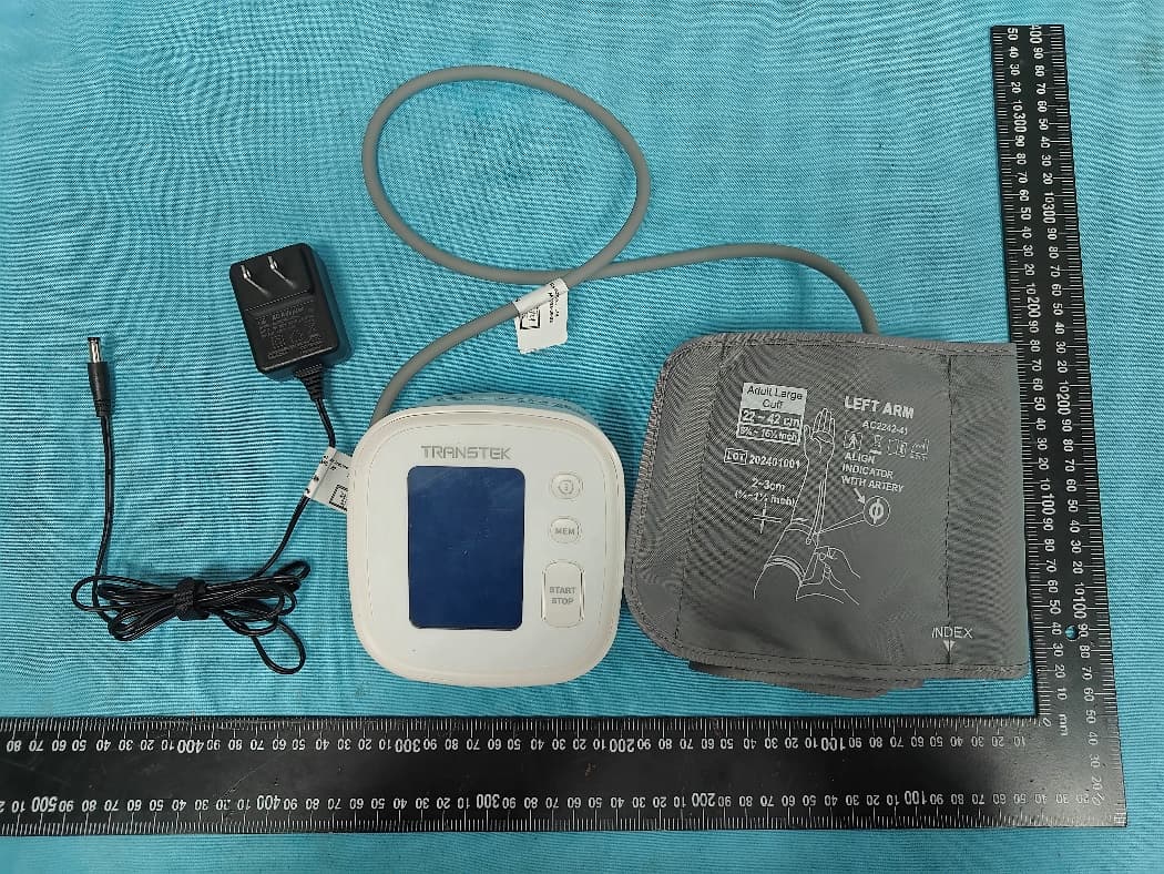
OU9BB-1597-G
Aug 08, 2024Blood Pressure monitor
Equipment Class
PCB - PCS Licensed Transmitter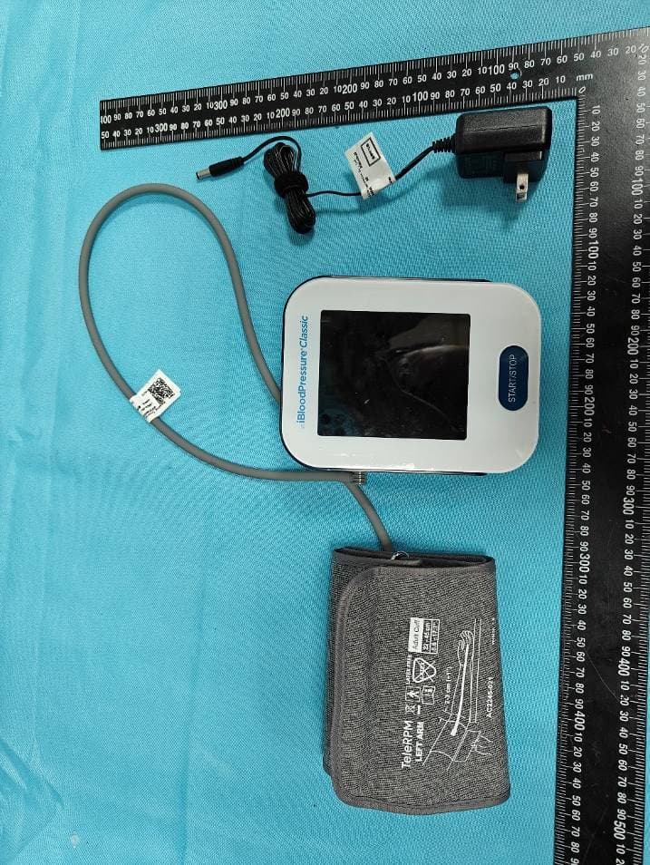
OU9LS802GAM2
Jun 16, 2024Blood pressure monitor
Equipment Class
PCB - PCS Licensed Transmitter
OU9-TMB2287B
Oct 15, 2023Blood pressure monitor
Equipment Class
DTS - Digital Transmission System