OUERR1TXPhotographic Flash Remote Control Transmitter
Paul C. Buff, Inc.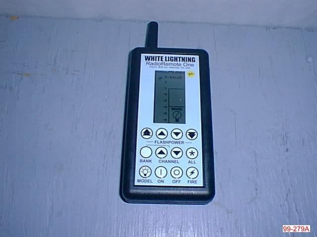
Click to zoom
Application Details
- Equipment Class
- DXX - Part 15 Low Power Communication Device Transmitter
- Date of Grant
- Mar 15, 2000
- Application Purpose
- Original Equipment
- Date of Application
- Dec 19, 1999
- Equipment Note
- Photographic Flash Remote Control Transmitter
- Frequency Range
- 916.50000000 - 916.50000000
- Company
- Paul C. Buff, Inc.
- Country
- United States
Documents & Files
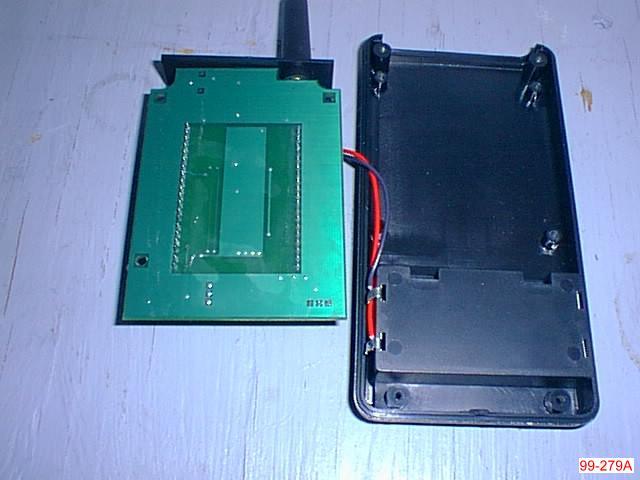
Document Text
Text extracted from the exhibit documents filed with the FCC. Open a document above to read the original.
Users Manual
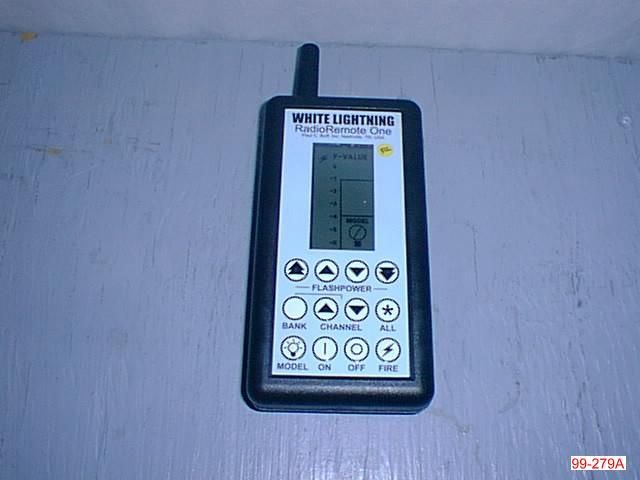
The channel ONand OFF buttons set each individual channel state.If a channel is set to OFF,it is taken out of the bracketing (ALL)mode,it is not firedby camera sync and all commands are ignored except ON. Backlit Liquid Crystal Display (LCD) indicates exact settings of flashpower, bank / channel information,as well as specific model lamp status. Bargraphindicator shows channel flashpower settings at a glance. Pressing a FLASHPOWERbut- ton raises or lowers flashpow- er.Increments in 1 f-stop (double-arrow)units or in 1/10 f-stop (single-arrow) units. Pressing and holding BANK while pressing up/down arrowCHANNELbuttons selects from Bank 1 to 16. Pressing the up/down arrow CHANNELbutton selects 1 of 16 possible channels. The MODELselect button scrolls through the three possible model lamp states - ON,OFF or TRACKING mode. The current MODEL status is indicated by the Model Lamp iconin the LCDwindow. WHITE LIGHTNING RadioRemote One Wireless Remote Control System (Includes Instructions for RadioRemote One Transmitter and RadioReciever One) 10 / 1999 Paul C.Buff,Inc./ WHITE LIGHTNING / 800-443-5542 2725 BransfordAve.• Nashville,TN 37204 • USA fax:615-383-0676 • website:http://www.white-lightning.com F-VALUEis a two-digit display showing channel flashpower in 1/10 f-stop units.Range is from +0.0 to -6.2 f-stops. BANK/CHANdisplay shows current channel.While pressing BANKbutton,display shows currently assigned bank. When using (ALL) mode,dis- play shows if a channel is over or under range by indicating lowest numbered channel out- of-range. ALLchannel mode indicator becomes active when pressing and holding the ALLbutton. Used for bracketing scenes while maintaining lighting ratios. The MODELlamp icon indi- cates one of three states - ON= blank,OFF= dark,and TRACKING= half-bulb. Pressing the ALLbutton once sends the current settings to all lights.Pressing and holding the ALL button together with anyFLASHPOWERbutton,rais- es or lowers all channels’ flash- power (unless a channel is out- of-range - see text) Pressing FIREtest flashes the channel number currently displayed in the CHAN window.Pressing ALL before,either once or holding,then pressing FIRE test flashes all lights in system. TRANSMITTER POWER ON/OFF switch controls either battery or DC power supply (if connected). CHANNELselect switch sets 1 of 16 receiver oper- ating channels in selected Bank. White Lightning remote jack con- nects here with RJ- 11 type modular type phone cable. Model lamp blinks when receiver is addressed letting you know system is working. DC POWER connector is located on top apron for easy access.Use onlyPaul C.Buff,Inc.approved DC power supplies. Auxiliary sync con- nector is located next to AC power connector.Used for flash units not equipped with White Lightning remote jack. LOW BATled blinks four (4) times on power up and when battery power has depleted to 1/3 level - about 100 hours.Blinks once each time a command is received from the transmitter. BANKselect switch sets system bank (1 of 16).All chan- nels are inclusive in this selected bank. Equipment Supplied: Each RadioRemote One Transmitter comes supplied with the following items: • Two "AA" batteries • Velcro strap • Peel-off Velcro adhesive mounting pad • Stereo mini-plug to 2-prong sync connector • Instruction manual Each RadioRemote One Receiver comes supplied with the following items: • DC power supply • Bank and Channel selection screwdriver• Velcro mounting strap • Peel-off Velcro adhesive mounting pad • 6 ft.modular telephone cable • Instruction manual © Copyright 1999 Paul C.Buff,Inc.,Nashville,TN,USA Ref # 112299RR1M R E C E I V E R Overview The RadioRemote One system provides full wireless remote control of all Paul C.Buff,Inc.White Lightning Ultra,UltraZap and X-Series flash units via the "To Light" jack.Most flash units from other manufacturers may be fired,but not adjusted,from the receiver's auxiliary sync jack via a suitable cable to fit the specific flash unit. C a u t i o n :The RR1 re c e i ver is designed for modern flash units with low current,low voltage (50V max) sync.Some older flash units have volt- ages as high as 400 volts at the sync terminals and could damage the unit. Setup In a typical lightning setup,the transmitter and all receivers should be assigned the same Bank number, with each receiver set to a different one of the 16 Channels.If there is more than one lighting setup in the same area,assigning a different Bank number to each lighting setup elimi- nates any interaction between the setups.Thus,as many as 16 photog- raphers can each operate up to 16 light units in the same area without i n t e r a c t i o n .It is important to remember that flash units with built in slave trippers will fire one another, re g a rdless of Bank and Channel assignments,if the slave function is not disabled.This is accomplished in White Lightning units by inserting an unconnected sync cord or a blank "1/4" Stereo Phone Plug" (available at Radio Shack stores) into the sync jack of the White Lightning unit. If you are operating in a studio environment you might choose to not disable the built in slaves.This will assure that if one receiver hap- pens to miss a fire command its light will fire anyhow via the flash received from the other flashes.This method will,however,not allow you to test fire individual light units from the RR1 transmitter. Camera Sync The transmitter should be con- nected to the camera sync jack via the cable supplied.Cameras with focal plane shutters should be set to 1/60" or slower shutter speed,while leaf shutter cameras may be set to 1/125" or slower.(An optional hot shoe adaptor may be required for cameras lacking a sync output jack). Operating Range Typical operating range should be from about 100' up to 400' or more and may be affected by a number of factors,including buildings,vegeta- tion,bodies of water and interfer- ence from other radio transmitters. Antennas should be kept vertical and the receivers should be mount-…
Text truncated - open the document above for the full version.
Block Diagram
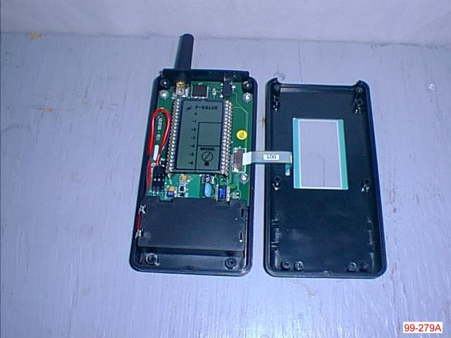
RISC Microcontroller 16.0 MHz LCD Driver LCD Display Membrane Switch Array EEPROM/Flash Memory HX2000 Transmitter Module 916.5MHz Antenna Camera Sync Input Switching Power Supply 3 Volt Battery I2C Figure 1 RR1TX Block Diagram
ID Label/Location Info
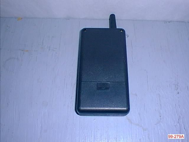
RadioRemoteOne Transmitter Label Quick Reference BANK + FLASH BANK + FLASH BANK + ON ALL then FIRE Press BANK Once Sync delay is 2.5 milliseconds See manual for details. FCC ID YYYRR1TX This device complies with part 15 of the FCC Rules. Operation is subject to the following two conditions: (1) this device may not cause harmful interference, and (2) this device must accept any interference received, including interference that may cause undesired operation. = Save Scene = Restore Scene = Factory Defaults = Fire All Lights = Backlight On Note: Label to be place on the rear of the RR1TX just above the battery door. RadioRemoteOne Receiver label Note: Label to be place on the rear of the RR1RX just above the battery door. FCC ID YYYRR1RX This device complies with part 15 of the FCC Rules. Operation is subject to the following two conditions: (1) this device may not cause harmful interference, and (2) this device must accept any interference received, including interference that may cause undesired operation.
ID Label/Location Info
RadioRemoteOne Transmitter Label Quick Reference BANK + FLASH BANK + FLASH BANK + ON ALL then FIRE Pr e s s BA NK On ce Sy nc de lay is 2 .5 millis e c on d s See manual f or details. FCC ID OUERR1TX T his devi ce com pl ies w ith par t 15 of th e FC C R ul es . Oper ati on i s su bj ec t t o t he fol low i ng tw o conditions: ( 1) thi s d evi ce m ay n ot c aus e harm ful i nt er fer e nce, and (2) t his device must ac cep t any in terfere nc e rec eived, i nclu din g i n ter fer enc e t hat m ay c aus e u ndesired operati on. = Save Scene = Re s tor e Sc ene = Factory Defaults = Fire A ll Lights = Bac klight On Note: Label to be place on the rear of the RR1TX just above the battery door.
Test Report
RF Emissions Test Report To Determine Compliance With: FCC, Part 15 Rules and Regulations Model numbers: RR1-TX November 8, 1999 Manufacturer:Paul C Buff 2725 Bransford Ave. Nashville, TN 37204 EMC Testing Laboratories, Inc. authorizes the above company to reproduce this report provided it is reproduced in its entirety EMC Testing Lab. (770) 781-9228 Test report no. 99-279A Page 2 of 1 1 7 7 Contents Section General Information .......................................................................1 Test Summary..................................................................................2 Standard Reference ........................................................................3 Test Method ..........................................................................4 Radiated Out of Band Emissions Measurements ...........................5 Fundamental Frequency Radiated Emissions Measurements .........6 Radiated emission measurements in accordance with 15.109 .........7 Configuration ............................................................................8 EMC Testing Lab. (770) 781-9228 Test report no. 99-279A Page 3 of 1 1 7 7 Section 1 General Information Manufacturer:Paul C Buff 2725 Bransford Ave. Nashville, TN 37204 Manufacturer representative:Mr. David Mundie Equipment covered by this report:Model no. RR1-TX Options covered by this report:None Equipment serial no.Prototype Test specifications:To determine compliance with: FCC, Part 15, Subpart C Rules and Regulations, Class B Test report number:99-279A Test commenced:November 6, 1999 Test completed:November 8, 1999 Test engineer:Kent Stewart Test Facility:The test facility used to perform these tests is on file with the FCC under file 31040/SIT, 1300F2 and located at: EMC Testing Laboratories, Inc. 2420 Oak Street West Cumming, GA. 30041-6456 EMC Testing Lab. (770) 781-9228 Test report no. 99-279A Page 4 of 1 1 7 7 Section 2 Test report summary sheet 1 of 2 Summary: TestsResults FCC, Part 15, Class B, Radiated emissions: Pass FCC, Part 15, Class B, Conducted emissions: N/A 1- The product(s) covered by this report was found to comply with the limits indicated in paragraph 15.109 Subpart B and 15.249, Part 15, Subpart C of the FCC Rules and Regulations. Note: The conducted emissions test was not performed since the EUT is battery operated with no means for connection to public mains. Product description: The product(s) covered by this report consisted of a model RR1-TX, battery operated light monitor remote control, intended for use with photography equipment. Model RR1-TX is an intentional pulsed radiator, which transmits at 916.5 MHz utilizing an average 50% duty cycle, (see manufacturers letter in section 9). Test configuration: The equipment under test was set-up and configured as specified by the manufacturer. 1- The EUT was connected to the following support peripherals. A) None 2- The EUT was connected to the following cables. A) None EMC Testing Lab. (770) 781-9228 Test report no. 99-279A Page 5 of 1 1 7 7 Test report summary sheet 2 of 2 Test operation: For all measurements, the equipment under test was and caused to function in a continuous mode of operation for maximum electrical activity as specified by the manufacturer. Specifically, the EUT was programmed to continuously send data when powered on. Modifications: The following modifications were required to comply with the indicated limits: 1- None Conclusion: With the above indicated modifications, the product(s) covered by this report has been tested and found to comply with the limits indicated in paragraph 15.249 of the FCC, Part 15, Subpart C Rules and Regulations and all subsequent limits indicated therein for a class B device. Tested by:Reviewed by: Kent StewartGene J. Bailey Laboratory ManagerEngineering Manager EMC Testing Laboratories, Inc.EMC Testing Laboratories, Inc. November 12, 1999November 12, 1999 EMC Testing Lab. (770) 781-9228 Test report no. 99-279A Page 6 of 1 1 7 7 Section 2 cont... This page intentionally left blank. (Reserved for future use) EMC Testing Lab. (770) 781-9228 Test report no. 99-279A Page 7 of 1 1 7 7 Section 3 STANDARD REFERENCE The following primary standards were used for this test: 1)ANSI C63.4-1992: Method of Measurements of Radio-Noise Emissions from Low- Voltage Electrical and Electronic Equipment in the 9 Khz to 40 Ghz. 2)US Code of Federal Regulations (CFR) 1998: Title 47, Part 15, Radio Frequency Devices, Subpart C, Intentional Radiators. EMC Testing Lab. (770) 781-9228 Test report no. 99-279A Page 8 of 1 1 7 7 Section 4 TEST METHOD INTRODUCTION: The product(s) covered by this report were subjected to electromagnetic interference emissions measurements to determine compliance with the FCC, Part 15 requirements. Radiated emissions were measured in accordance with Methods of Measurement of Radio-Noise Emissions from Low-Voltage Electrical and Electronic Equipment in the Range of 9 Khz to 40 Ghz, C63.4. MEASUREMENT CALCULATIONS: Radiated Emissions: For radiated emissions measurements, the signal attenuation due to impedance losses in the antenna and signal cable was significant and was added to the spectrum analyzer reading to give corrected signal strength reading. If a preamplifier was used, the signal gain was subtracted from the signal strength reading. Radiated emissions data was specified as microvolt per meter (μV/m) of radiated field strength. Radiated emissions (μV/m) = Analyzer reading (μV) plus antenna factor (dB) plus cable factor (dB) minus Amplifier gain (dB) RADIATED EMISSIONS MEASUREMENT: Radiated emissions measurements were performed at an open field test site. The receiving antenna was positioned 3 meters from the equipment under test as indicated below, along the center axis of the test site. Measurements were made with broadband antennas and if necessary, detected emissions were verified with dipole antennas. The dipole antenna was manually tuned to the signal frequency by adjusting the length of the…
Text truncated - open the document above for the full version.
Contact Information
Applicant
Brian Lennon(Technical Director)
Technical Contact
EMC Testing LaboratoriesGene J Bailey
[email protected]770-781-9228
2420 Oak Street West · Cumming, Georgia · United States
Non-Technical Contact
EMC Testing LaboratoriesGene J Bailey
[email protected]770-781-9228
Test Firm
EMC Testing Laboratories, Inc.Gene Bailey
Technical Specifications
| # | Rule Parts | Frequency Range | Power Output |
|---|---|---|---|
| 1 | 15C | 916.5 MHz - 916.5 MHz | - |
Other Applications from Paul C. Buff, Inc.
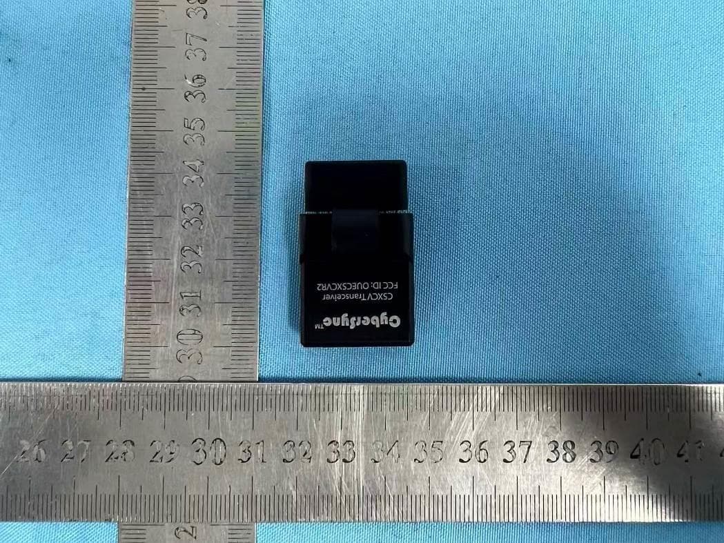
OUECSXCVR2
Dec 07, 2025CSXCV Transceiver
Equipment Class
JAB - Part 15 Class B Digital Device
OUECEL500
Apr 13, 2023Celestial
Equipment Class
JAB - Part 15 Class B Digital Device
OUECST3
Apr 28, 2022CST3
Equipment Class
DXX - Part 15 Low Power Communication Device Transmitter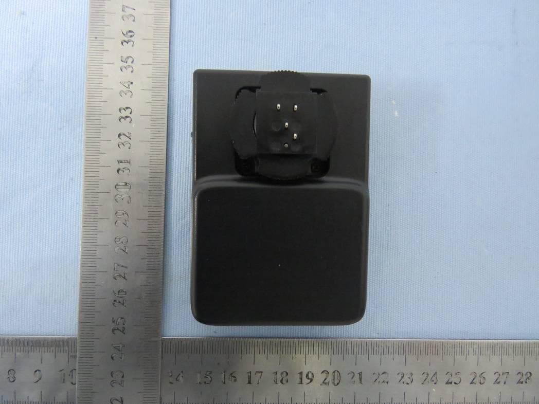
OUEPCBHUB
Mar 09, 2021HUB
Equipment Class
DXX - Part 15 Low Power Communication Device Transmitter
OUELINK800
Nov 22, 2020LINK800WS
Equipment Class
DXX - Part 15 Low Power Communication Device Transmitter