OUS420ALow Power Television
UBS-Axcera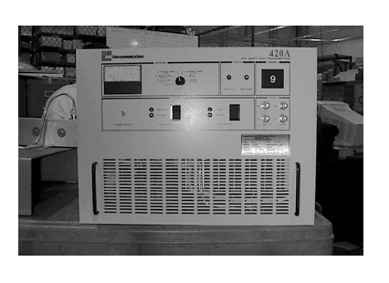
Click to zoom
Application Details
- Equipment Class
- TBC - Licensed Broadcast Station Transmitter
- Date of Grant
- Apr 02, 2000
- Application Purpose
- Original Equipment
- Date of Application
- Jan 06, 2000
- Equipment Note
- Low Power Television
- Frequency Range
- 174.00000000 - 216.00000000
- Company
- UBS-Axcera
- Country
- United States
Documents & Files
Document Text
Text extracted from the exhibit documents filed with the FCC. Open a document above to read the original.
Users Manual
100 Watt High Band VHF TransmitterChapter 1, Introduction 420A, Rev. 01-1 Chapter 1 Introduction This manual explains the installation, setup, alignment, and maintenance procedures for the 420A 100 Watt High Band VHF Transmitter. It is important that you read all of the instructions, especially the safety information in this chapter, before you begin to install or operate the unit. 1.1 Manual Overview This instruction manual is divided into four chapters and an appendix. Chapter 1, Introduction, contains information on safety, maintenance, return procedures, and warranties. The second chapter describes the transmitter and includes discussions on system control and status and remote control connections. Chapter 3 explains how to unpack, install, setup, and operate the transmitter. Chapter 4, Detailed Alignment Procedures, provides information on adjusting the system assemblies for optimal operation. The appendix contains assembly drawings for the system. 1.2 Safety The 100-watt VHF transmitters manufactured by the Broadcast Systems Division of ADC Telecommunications are designed for ease of use and repair while providing protection from electrical and mechanical hazards. Listed throughout the manual are notes, cautions, and warnings concerning possible safety hazards that may be encountered while operating or servicing the transmitter. Please review these warnings and familiarize yourself with the operation and servicing procedures before working on the transmitter. Read All Instructions – All of the operating and safety instructions should be read and understood before operating this equipment. Retain Manuals – The manuals for the transmitter should be retained at the transmitter site for future reference. We provide two sets of manuals for this purpose; one set can be left at the office while one set can be kept at the site. Heed Notes, Warnings, and Cautions – All of the notes, warnings, and cautions listed in this safety section and throughout the manual must be followed. Follow Instructions – All of the operating and use instructions for the transmitter should be followed. Cleaning – Unplug or otherwise disconnect power from the equipment before cleaning. Do not use liquid or aerosol cleaners. Use a damp cloth for cleaning. Ventilation – Openings in the cabinets and tray front panels are provided for ventilation. To ensure reliable operation, and to protect the unit from overheating, these openings must not be blocked. Servicing – Do not attempt to service this product yourself until becoming familiar with the equipment. If in doubt, refer all servicing questions to qualified ADC Telecommunications service personnel. Replacement Parts – When replacement parts are used, be sure that the parts have the same functional and performance characteristics as the original part. Unauthorized substitutions may result in fire, electric shock, or other hazards. Please contact the ADC Telecommunications Technical Service Department if you have any questions regarding service or replacement parts. 100 Watt High Band VHF TransmitterChapter 1, Introduction 420A, Rev. 01-2 1.3 Maintenance The 420A is designed with components that require little or no periodic maintenance except for the routine cleaning of the fans and the front panels of the trays. The amount and time interval between cleanings depends on the conditions within the transmitter room. While the electronics have been designed to function even if covered with dust, a heavy buildup of dust, dirt, or insects will hinder the effectiveness of the cooling of the components. This could lead to a thermal shutdown or premature failure of the affected trays. When the front panels of the trays become dust covered, the top covers should be removed and any accumulated foreign material removed. A vacuum cleaner, utilizing a small wand-type attachment, is an excellent way to suction out the dirt. Alcohol and other cleaning agents should not be used unless you are certain that the solvents will not damage components or the silk- screened markings on the trays and boards. Water-based cleaners can be used, but do not saturate the components. The fans and heatsinks should be cleaned of all dust or dirt to permit the free flow of air for cooling purposes. It is recommended that the operating parameters of the transmitter be recorded from the meters on the trays and the system metering control panel at least once a month. It is suggested that this data be retained in a rugged folder or envelope for the life of the equipment. Photocopies of the log sheet should be made for continued data entries. 1.4 Material Return Procedure To insure the efficient handling of equipment or components that are returned for repair, ADC Telecommunications requests that each returned item be accompanied by a Material Return Authorization Number (MRA#). An MRA# can be obtained from any ADC Telecommunications Field Service Engineer by calling the ADC Telecommunications Field Service Department, Broadcast Systems Division, at (724) 941-1500 or 1-800-215-2614. This procedure applies to all items sent to the Field Service Department regardless of whether the item was originally manufactured by ADC Telecommunications. Note: To prevent damage to the product during shipping, ADC Telecommunications will supply a shipping container to the customer at no cost. When equipment is sent to the field on loan, an MRA# is included with the unit. The MRA# is intended to be used for the return of the unit to ADC Telecommunications. In addition, all shipping material should be retained for the return of the unit to ADC Telecommunications. Replacement assemblies are also sent with an MRA# to allow for the proper routing of the exchanged hardware. Failure to close out these types of MRA#s will normally result in the customer being invoiced for the value of the loaner item or the exchange assembly. When shipping an item to ADC Telecommunications, please include the MRA# on the packing list and on the AD…
Text truncated - open the document above for the full version.
Users Manual
100 Watt High Band VHF Transmitter Chapter 2, System Description 420A, Rev. 02-1 Chapter 2 System Description The 420A is a complete 100 watt high band VHF solid-state internally diplexed television transmitter that operates at a nominal visual output power of 100 watts peak sync and an average aural output power of 10 watts at a 10 dB A/V ratio,10% sound. The 420A has been submitted for type acceptance to the FCC; the relevant FCC identifier for the 420A is _________________. 2.1 420A System Overview The 420A (1066428) consists of (A1) a 100-watt, high-band VHF exciter/amplifier tray (1066308) and (A2) a bandpass filter assembly. The exciter/modulator section of the 100- watt, high-band VHF exciter/amplifier tray operates using either baseband audio and video inputs. However, if the (optional) 4.5 MHz composite input kit (1273-1128) is purchased, the 4.5 MHz composite input or the baseband video and audio inputs are used to produce a diplexed, modulated, on-channel frequency visual + aural RF output. The switching between the 4.5 MHz generated by the baseband inputs or by the 4.5 MHz composite input is accomplished by a relay, on the sync tip clamp modulator board. The relay is controlled by a baseband select which connects to J18-6 and 7 on the rear of the tray. To operate the transmitter with the (optional) 4.5 MHz composite input kit using baseband inputs, the baseband video must be connected to J1 or J2, the baseband audio must be connected to the proper input jack, and a baseband select must be connected to J18-6 and 7. To operate the transmitter with the (optional) 4.5 MHz composite input kit using the 4.5 MHz composite input, the 4.5 MHz composite input must be connected to J1 or J2 and the baseband select must be removed from J18-6 and 7. The exciter/modulator section of the tray takes the baseband audio and video inputs, or the (optional) 4.5 MHz composite input, and produces a combined 45.75 MHz + 41.25 MHz IF output that connects to J32 on the ALC board. The combined IF output of the ALC board connects to the mixer/amplifier assembly where it is upconverted and filtered to the on- channel frequency visual + aural RF output. The RF is filtered and amplified in the amplifier section to the 100-watt output power level. The RF output is filtered in the bandpass filter assembly and fed to the antenna via the transmission line. The exciter and upconverter section of the tray operate when the circuit breaker CB1 is on, but the amplifier section only operates when the transmitter is in Operate. This occurs because the switching power supply that supplies the operating voltages to the amplifier section has an inhibit command applied to it, shutting it off as long as the transmitter is in Standby. 2.1.1 Exciter Section The baseband video and audio inputs to the transmitter connect to the rear panel of the tray. The baseband video or the (optional) 4.5 MHz composite input connects to jack (J2), which is a loop- through connected to jack (J1). By removing the termination jumper on the sync tip clamp/modulator board, jack (J1) can be used as a connection for the baseband video or the 4.5 MHz composite input to another transmitter. The baseband audio input connects to the terminal block (TB1) for balanced 100 Watt High Band VHF Transmitter Chapter 2, System Description 420A, Rev. 02-2 audio or to the BNC jack (J3) for composite audio, which is a loop-through connected to jack (J13). There are also connections for the remote monitoring and operation of the transmitter at the "D"-connector jacks (J10 and J11). The baseband audio connects to (A4) the aural IF synthesizer board (1265-1303), in the exciter section, which provides the amplification for each of the three possible audio inputs and the amplifier circuit that supplies the single audio output. The board has the 4.5 MHz VCO and the aural modulation circuitry that produces the modulated 4.5 MHz output. The board also contains a PLL circuit to maintain the precise 4.5 MHz separation between the aural (41.25 MHz) and visual (45.75 MHz) IF frequencies. The video input or 4.5 MHz composite input to the exciter section connects to (A5) the sync tip clamp/modulator board (1265-1302) that takes the video input and produces a sync tip clamped and modulated visual IF + aural IF output at the output jack J20. If the optional 4.5 MHz composite input is purchased, the input is directed out of the sync tip camp/modulator board to the (A24) composite 4.5 MHz filter board (1227- 1244) and the (A25) 4.5 MHz bandpass filter board (1265-1307). These two boards process the 4.5 MHz composite input and produce the video that connects back to the sync tip clamp/modulator board at J27. The clamp portion of the board maintains a constant peak of sync level of the video signal over varying average picture levels (APL). The modulator portion of the board contains the circuitry that generates an amplitude-modulated, vestigial-sideband IF signal output at 45.75 MHz. The 45.75 MHz is generated by (A7) the IF oven oscillator board (1191-1404) and connected (+5 dBm) to the sync tip clamp/modulator board. The combined visual IF + aural IF output (0 dBm) connects to J32 on (A8) the ALC board and then through relays to the rest of the ALC board. The ALC board gives the operator control over the output power level of the transmitter by adjusting the level of the combined IF signal. The IF connects out of the board at J3 and is directed to (A9) an IF phase corrector board (1227-1250). The IF signal is phase corrected as needed and fed back to the ALC board. 2.1.2 Upconverter Section The output of the ALC board (0 dBm) connects to (A11-A1) the filter/mixer board (1150-1102), in the (A11) mixer/amplifier enclosure (1065007), which takes the LO and heterodynes it with the combined IF. This signal is then fed to the high-band VHF filter/amplifier board, high output (1064150), that amplifies the RF signal and feeds it to the (A23) high-band amplifier heatsink assembly (106500…
Text truncated - open the document above for the full version.
Users Manual
100 Watt High Band VHF Transmitter Chapter 3, Installation and Setup Procedures 420A, Rev. 03-1 Chapter 3 Installation and Setup Procedures There are special considerations that need to be taken into account before the 420A transmitter can be installed. For example, if the installation is completed during cool weather, a heat-related problem may not surface for many months, suddenly appearing during the heat of summer. This section provides information that will assist in planning for the installation and set up of the transmitter. 3.1 Site Considerations The transmitter requires an AC input line of 115 or 230 VAC with a rating of 10 amps. Make sure that the proposed site for the transmitter has the voltage requirements that are needed. The 420A is designed and built to provide long life with a minimum of maintenance. The environment in which it is placed is important and certain precautions must be taken. The three greatest dangers to the transmitter are heat, dirt, and moisture. Heat is usually the greatest problem, followed by dirt, and then moisture. Overtemperature can cause heat-related problems such as thermal runaway and component failure. Each amplifier tray in the transmitter contains a thermal interlock protection circuit that will shut down that tray until the temperature drops to an acceptable level. A suitable environment for the transmitter can enhance its overall performance and reliability and maximize revenues by minimizing down time. A properly designed facility will have an adequate supply of cool, clean air, free of airborne particulates of any kind, and without excessive humidity. An ideal environment requires temperatures in the range of 40° F to 70° F throughout the year, reasonably low humidity, and a dust-free room. It should be noted that this is rarely if ever attainable in the real world. However, the closer your environment is to this design, the greater the operating capacity of the transmitter. Although the fans and blowers designed and built into the transmitter will remove the heat from within the cabinet, additional means are required for removing heat from the building. To achieve this, a few considerations should be taken into account. The first step is to determine the amount of heat to be removed. There are generally three sources of heat that must be considered. The first and most obvious is the heat from the 100-watt transmitter itself. This can be determined by subtracting the average power to the antenna (69.5 watts) from the input power (750 watts). This number in watts (680.5) is then multiplied by 3.41, which gives 2320, the BTUs to be removed every hour. The second source of heat is other equipment in the same room. This number is calculated in the same way as the equation for BTUs. The third source of heat is equally obvious but not as simple to calculate. This is the heat coming through the walls, roof, and windows on a hot summer day. Unless the underside is exposed, the floor is usually not a problem. Determining this number is usually best left up to a qualified HVAC technician. There are far too many variables to even estimate this number without detailed drawings of the site showing all construction details. The sum of these three sources is the total amount of heat that must be removed. There may be other sources of heat, such as personnel, and all should be taken into account. Now that the amount of heat that must be removed is known, the next step is to determine how to accomplish this. The 100 Watt High Band VHF Transmitter Chapter 3, Installation and Setup Procedures 420A, Rev. 03-2 options are air conditioning, ventilation, or a combination of the two. Air conditioning is always the preferred method and is the only way to create anything close to an ideal environment. Ventilation will work if the ambient air temperature is below 100° F, or about 38° C, and the humidity is kept at a reasonable level. In addition, the air must be adequately filtered to ensure that no airborne particulates of any kind will be carried into the transmitter. A combination of air conditioning for summer and ventilation during the cooler months is acceptable when the proper cooling cannot be obtained through the use of ventilation alone and using air conditioning throughout the year is not feasible. Caution: The operation of air conditioning and ventilation simultaneously is not recommended. This can cause condensation in transmitters. For tube type transmitters, this can be especially serious if the condensation forms in the tube cavity and creates damaging arcs. The following precautions should be observed regarding air conditioning systems: 1. Air conditioners have an ARI nominal cooling capacity rating. In selecting an air conditioner, do not assume that this number can be equated to the requirements of the site. Make certain that the contractor uses the actual conditions that are to be maintained at the site in determining the size of the unit. With the desired conditioned room temperature under 80° F, the unit must be derated, possibly by a substantial amount. 2. Do not have the air conditioner blowing directly onto the transmitter. Under certain conditions, condensation may occur on, or worse in, the transmitter. 3. Do not isolate the front of the transmitter from the back with the thought of air conditioning only the front of the unit. Cooling air is drawn in at the front of all transmitters and in the front and back of others. Any attempt to isolate the front of the transmitter from the rear of the unit will adversely affect the cooling air flow. 4. Interlocking the transmitter with the air conditioner is recommended to keep the transmitter from operating without the necessary cooling. 5. The periodic cleaning of all filters is a must. When using ventilation alone, the following general statements apply: 1. The blower, with attendant filters, should be on the inlet, thereby pressurizing the room and preventing the ingress of dirt. 2. The inlet …
Text truncated - open the document above for the full version.
Users Manual
100 Watt High Band VHF Transmitter Chapter 4, Detailed Alignment Procedures 420A, Rev. 04-1 Chapter 4 Detailed Alignment Procedures If this transmitter contains the (optional) 4.5 MHz composite input kit, the baseband video input is used when the baseband video is connected to J2 and a baseband select is connected to J18 pins 6 and 7 on the rear of the tray. Check that the RF output at J15 of the transmitter is terminated into a dummy load of at least 100 watts. While performing the alignment, refer to the Test Data Sheet for the transmitter and compare the final readings from the factory with the meter readings on the tray. They should be very similar. If a reading is more than 10% different, a problem with the tray may exist. Switch on the on/off AC circuit breaker on the rear of the tray. 4.1 Alignment of the 420A Transmitter 4.1.1 Baseband Section This tray has adjustments for video and audio modulation levels and other related parameters. Connect an NTSC composite video test signal input (1 Vpk-pk) or an (optional) 4.5 MHz composite input to the transmitter video input jack J2 on the rear of the tray. Note: J2 is a loop-through connected to J1. It can be used as a baseband video source if the jumper W1 on J3 of the sync tip clamp/modulator board is removed. Connect the baseband audio, if it is balanced audio (+10 dBm), to the terminal block (TB1) or connect the composite audio (stereo) (1 Vpk-pk) to the BNC jack (J13). Note: J13 is a loop-through connected to J3. It can be used as a composite audio source if the jumper W4 on J12 of the aural IF synthesizer board is removed. The baseband audio is not used with the (optional) 4.5 MHz composite input. Observe the front panel meter on the tray. In the video position, the meter indicates active video from ≅ 0.3V to 1.0V. With an input video of 1 Vpk-pk, the display should indicate 100 IRE units at white. If the reading is at not the proper level, the overall video level can be changed by adjusting the video level control (R15) on (A5) the sync tip clamp/modulator board (1265-1302). Switch the meter to the audio position that will indicate the audio deviation (modulation level) of the signal; the meter indicates from 0 to 100 kHz. The aural IF synthesizer board was factory set for ±25 kHz deviation with a balanced audio input of +10 dBm. If the reading is not the correct level, adjust the balanced audio gain pot R13 on the aural IF synthesizer board, as needed, to attain the ±25 kHz deviation. The aural IF synthesizer board was factory set for ±75 kHz deviation with a composite audio input of 1 Vpk-pk. If the reading is not correct, adjust the composite audio gain pot R17 on the aural IF synthesizer board, as needed, for the ±75 kHz deviation. 100 Watt High Band VHF Transmitter Chapter 4, Detailed Alignment Procedures 420A, Rev. 04-2 4.1.2 IF/Upconverter Section The upconverter section of the tray includes adjustments for automatic level control (ALC), linearity (amplitude pre- distortion), and incidental phase (phase change vs. level) pre-distortion for correction of the non-linearities of the RF amplifier section of the tray. The upconverter section also includes adjustments to the local oscillator chain tuning and the local oscillator center frequency tuning. Both of these alignments were completed at the factory and should not need to be adjusted at this time. Move the Operate/Standby switch located on the front panel of the tray to Standby. The set-up of the RF output includes an adjustment to the drive level of the amplifier section of the tray, the adjustment of the linearity, and the (optional) incidental phase predistortion which compensate for any nonlinear response of the amplifier section. Verify that all red LEDs on the ALC board are extinguished. The following list details the meaning of each LED when illuminated: • DS1 (Input fault) – Indicates that abnormally low or no IF is present at the input of the board • DS2 (ALC fault) – Indicates that the ALC circuit is unable to maintain the signal level requested by the ALC reference due to excessive attenuation in the linearity or ICPM corrector signal path or that jumper W3 on J6 is in the Manual ALC Gain position • DS3 (Video loss) - Indicates a loss of video at the input of the board • DS4 (Visual mute) - Indicates that a Visual Mute command is present (The visual mute is not used in this system.) • DS5 (Modulator Enable) - Indicates that the modulator output is selected Check that the jumper W3 on J6 of (A8) the ALC board (1265-1305) is in the Auto position and adjust the power gain pot (R1) on the front panel of the tray to obtain +0.85 VDC on the front panel meter in the ALC position. Move the jumper W3 on J6 to the Manual position and adjust R87 on the ALC board for +0.85 VDC on the front panel meter in the ALC position. Move the jumper back to Auto; this is the normal operating position. The detected IF signal level at J19-2 of the ALC board is connected to the transmitter control board. This signal supplies the voltage to the high-band mixer/amplifier board where it is used as an automatic gain control (AGC) for the RF output signal of the upconverter section in the amplifier section of the tray. 4.1.3 Amplifier Section of the Tray Note: Power is applied to the amplifier boards when the transmitter is switched to Operate. Switch the transmitter to Operate and verify that the visual power reading on the front panel meter is 100%. If not, adjust the front panel power adjust pot to achieve 100%. Switch the input video test source to select an NTSC 3.58 MHz modulated staircase or ramp test waveform. Set up the station demodulator and monitoring equipment to monitor the differential gain and phase of the RF output signal. If a synchronous demodulator having a quadrature video output is available, it can be used with an X-Y oscilloscope to display incidental carrier phase modulation (ICPM). As shipped, the exciter was preset to include linearity (gain vs. level) and incidenta…
Text truncated - open the document above for the full version.
Users Manual
100 Watt High Band VHF Transmitter Appendix A, Assembly Drawings and Parts Lists 420A, Rev. 0A-1 420A Transmitter 100W H. B. VHF Transmitter Block Diagram ........................................... 1066347 100W H. B. VHF Transmitter Interconnect .............................................. 1066348 100 Watt H.B. VHF Exciter/Amplifier Tray Block Diagram .................................................................................... 1065005 Assembly Drawing............................................................................... 1066430 Interconnect ....................................................................................... 1065006 Flip Plate Assembly Parts List................................................................ 1065009 VHF Bandpass Filter Assembly Assembly Drawing............................................................................... 1077192 Interconnect ....................................................................................... 1077196
Users Manual
100 Watt VHF Transmitter Appendix B, Subassembly Schematics 420A, Rev. 0B-1 Output Coupler Board ..................................................................................1088-3104 Channel Oscillator Board, Dual Oven .............................................................1145-3201 (Optional) VCXO Board, Dual Oven ..............................................................1145-3204 Filter/Mixer Board........................................................................................1150-3102 x4 Multiplier Board ......................................................................................1174-3112 IF Carrier Oven Oscillator Board, 45.75 MHz ..................................................1191-3404 High Band Amplifier Board ...........................................................................1218-3201 Delay Equalizer Board..................................................................................1227-3204 (Optional) Composite 4 MHz Filter Board .......................................................1227-3244 IF Phase Corrector Board .............................................................................1227-3250 Sync Tip Clamp/Modulator Board, System M/N...............................................1265-3302 Aural IF Synthesizer Board, 4.5 MHz .............................................................1265-3303 ALC Board ..................................................................................................1265-3305 (Optional) 4.5MHz Bandpass Filter Board .......................................................1265-3307 Visual/Aural Metering Board, System M/N ......................................................1265-3309 Transmitter Control Board ............................................................................... 1069366 +12V(4A)/-12V(1A) Power Supply Board .......................................................1265-3312 Overcurrent Protection Board .......................................................................1273-3130 High Band VHF Filter Amplifier Board, High Output ............................................ 1063392
Users Manual
1 1 2 2 3 3 4 4 5 5 6 6 7 7 8 8 9 9 10 10 11 11 12 12 13 13 14 14 15 15 16 16 17 17 AA BB CC DD EE FF GG HH II JJ KK RMT MAN IND. RMT AUTO IND. MAN AUTO AUTO/MAN RTN RTN MANUAL AUTO RMT VID FLT IND RTN -12V N.C. VID FLT RTN VIDEO FAULT VID FLT VID FLT RTN KEY KEY N.C. +12V KEY MOD SEL RTN MOD SEL RMT REC FLT IND. RTN LO=FAULT HI=FAULT OPERATE RTN STANDBY INTERLOCK RTN OVERTEMP OVER TEMP STANDBY OPERATE DISABLE RTN RTN KEY PS DISABLE RTN ENABLE +12V +12V +12V +12V RTN RTN RTN RTN RTN UNLOCK MUTE POWER RAISE POWER LOWER RTN GND N.C. KEY ENABLE ENABLE ENABLE ENABLE PIN ATTEN BIAS AGC REF W2 ALC ALC RTN ALC RTN RTN RTN ALC ALC RTN KEY N.C. VSWR CUTBACK RTN N.C. KEY +12V RTN -12V AUDIO RTN VIDEO RTN KEY RTN N.C. KEY METER (+) METER (-) EXCITER KEY RTN AUR VISUAL RTN RTN REFL RTN RTN RTN RTN REFL AURAL VISUAL EXCITER RTN RCVR ALC NOTES: 1) J1 IS A 25 POS "D" CONNECTOR. 2) J8 IS A 37 POS "D" CONNECTOR. 3) ALL FETS ARE BS170. 4) ALL CAPACITORS ARE uF UNLESS NOTED OTHERWISE. 5) ALL RESISTORS ARE 1/8W UNLESS NOTED OTHERWISE. OPERATE/ STANDBY LO = OPERATE POWER ADJ VSWR CUTBACK ALC FAULT ALC FAULT THRESOLD AUDIO CAL VIDEO CAL ALC CAL Q26 NOT USED IN ASSEMBLY RTN AMB TEMP DWB DWB 9/20/99 9/20/99 1069366A0 SCHEMATIC, XMTR CONTROL BD. (1068933) PJK 8/24/99 D1 OF 1 ADC Telecommunications REV ECO DATEAPV TITLE THIS PRINT IS THE PROPERTY OF ADC, IT SHALL NOT BE COPIED WITHOUT PERMISSION MATERIAL FINISH DWN CHK REL SCALESHEET REV REV ECO DATE APV DWG. NO. --- ----- ----- +12V+12V -12V +12V +12V +12V+12V -12V +12V +12V +12V +12V -12V +12V +12V +12V +12V +12V +12V +12V +12V +12V +12V +12v +12V +12V +12V +12V -12V -12V +12V +12V -12V +12V +12V -12V +12V -12V +12V -12V +12V +12V -12V +12V +12V -12V -12V +12V +12V -12V +12V -12V +12V -12V -12V +12V -12v +12v +12V +12V Q23 Q22 Q21 DS4 YELLOW DS3 GREEN R49 1.2K R48 1.2K CR3 1N914 CR4 1N914 C16 .1 S2 1 2 3 J8-6 6 J8-7 7 J8-32 32 J8-9 9 J8-8 8 J8-36 36 J8-25 25 J8-31 31 Q17 J1-24 24 J1-25 25 J1-2 2 J1-23 23 R29 10 C8 .01 R30 1.2K DS9 RED Q16 R31 10K J1-1 1 J7 1 2 3 4 5 J10 1 2 W1 J17 1 2 3 4 J8-10 10 J8-11 11 J8-34 34 R32 100 CR12 1N914 R33 1K C10 .01 CR6 1N914 R34 1M C12 .1 C37 .1 R35 10K CW 3 2 1 C11 .01 DS8 RED R89 1.2K R36 1.2K Q15 R37 10K C9 .01 R39 1K R38 1K U5B MC14001BCP 5 6 4 14 7 R62 .22 Q18 + C13 10 35V R41 100 R88 150K R42 470K C15 .1 C14 .01 R43 4.7K R44 10K U5A 1 2 3 14 7 U5D 12 13 11 14 7 U5C 8 9 10 14 7 R45 10K R77 2.2M R78 2.2M C34 .01 C35 .01 Q19 Q20 J8-21 21 CR2 1N914 CR1 1N914 S1 1 2 3 J8-22 22 J8-20 20 DS5 GREEN J8-24 24 R4 100 R5 1.2K C3 .1 J8-23 23 J8-1 1 J12 1 2 3 U4B MC14072BCP 9 10 11 12 13 14 7 R1 10K Q1 Q2 DS1 YELLOW DS2 GREEN R6 100 Q3 R7 1.2K C4 .1 R8 10K J1-4 4 J1-16 16 Q4 Q24 J18 1 2 3 4 C36 .1 J1-3 3 J8-19 19 R50 100/2W CR7 1N4007 J8-18 18 R51 100/2W CR8 1N4007 J8-16 16 R52 100/2W CR9 1N4007 J8-17 17 R53 100/2W CR10 1N4007 J8-15 15 J8-14 14 J8-13 …
Text truncated - open the document above for the full version.
Contact Information
Applicant
David Hewitt(Engineering Manager)
Non-Technical Contact
ADC TelecommunicationsHenry F Lipput
724-941-1500
Technical Specifications
| # | Rule Parts | Frequency Range | Power Output | Emission | Tolerance |
|---|---|---|---|---|---|
| 2 | 74G | 174 MHz - 216 MHz | 10 W | 250KF3E | 250 Hz |
Other Applications from UBS-Axcera

OUSCU0TD-5-UBS
Mar 27, 2014200W UHF Digital Transmitter
Equipment Class
TBC - Licensed Broadcast Station Transmitter
OUSCL1TC-4
Sep 17, 2013400-Watt, 1.6 GHz DVB-H Transmitter
Equipment Class
TNB - Licensed Non-Broadcast Station Transmitter
OUSCLV2TD-4
Aug 22, 2013Low Band VHF Digital Broadcast Transmitter
Equipment Class
TBC - Licensed Broadcast Station Transmitter
OUSCHV4TD
Jun 14, 20123000-Watt VHF Digital Transmitter
Equipment Class
TBC - Licensed Broadcast Station Transmitter
OUSCU0TD-5
Dec 14, 2011200 Watt UHF Digital Transmitter
Equipment Class
TBC - Licensed Broadcast Station Transmitter