OUS5543A8-Watt BRS/EBS Digital Frequency Agile Transmitter
UBS-Axcera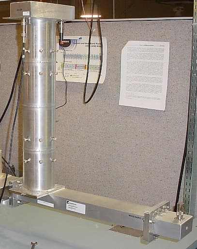
Click to zoom
Application Details
- Equipment Class
- TBC - Licensed Broadcast Station Transmitter
- Date of Grant
- Dec 27, 2007
- Application Purpose
- Original Equipment
- Date of Application
- Nov 13, 2007
- Equipment Note
- 8-Watt BRS/EBS Digital Frequency Agile Transmitter
- Frequency Range
- 2572.00000000 - 2614.00000000
- Company
- UBS-Axcera
- Country
- United States
Documents & Files
Document Text
Text extracted from the exhibit documents filed with the FCC. Open a document above to read the original.
Users Manual
OPERATION MANUAL 5543A DIGITAL AGILE TRANSMITTER AXCERA, LLC 103 FREEDOM DRIVE P.O. BOX 525 LAWRENCE, PA 15055-0525 USA (724) 873-8100 • FAX (724) 873-8105 www.axcera.com • [email protected] SYSTEM 5543A DIGITAL AGILE PAGE 1 INSTALLATION PROCEDURE UNPACKING Please inspect all material thoroughly upon arrival. Axcera certifies that upon leaving our facility the equipment was undamaged and in proper working order. The shipping container should be inspected for obvious damage indicative of rough handling. Remove the unit(s) from the shipping container and inspect for damage. Check for dents, and scratches, or a broken switch, meter or connector. Remove the top cover of the unit and again inspect for shipping damage. Extract all packing material from inside and around the unit. Check for loose hardware and connectors, retighten if needed. Any claims against in-transit damage should be directed to the carrier. Save all packing material in case it is needed in the future. INSTALLATION OF TRAY(S) Ì Units are shipped with chassis slides mounted to the each side. Included in the Installation Material Kit are two cabinet mount slide assemblies that will be mounted in the rack. Install the Tray slides into the cabinet. Refer to the "Cabinet Mounting Instructions Slides Drawing" which follows, for detailed instructions. Ì Slide the unit into the cabinet. If it does not slide in and out smoothly, some adjustment is necessary. Pull out the unit (only enough for clearance) and loosen the hardware holding the cable slides to the cabinet. Move the front of the Tray up or down or side to side to remove the rubbing. Retighten the hardware after the adjustment is complete. Ì Also included with the unit is a cable retractor assembly, which consists of two parts, a cabinet mount retractor and a tray mount retractor. n The cabinet mount retractor has a long aluminum channel hinged to a mounting piece with two bolts. This is mounted to the rear of the left hand, facing the front of the unit, cabinet mount slide assembly. n The retractor is a short aluminum channel hinged to a slide mount. This piece slides into a receptacle mounted to the rear panel of the unit. These cable retractors work together to move the wire harness and coaxial cables in and out with the movement of the unit to avoid pinched wires. Ì After the units(s) are physically in place, the process of interfacing them into the system begins by making connections to the back of the units. SYSTEM 5543A DIGITAL AGILE PAGE 2 CABINET MOUNTING INSTRUCTIONS FOR SLIDES DRAWING CONNECTIONS Once all equipment is in place, making connection to the back of the tray (s) is a relatively simple process. Each wire is clearly marked with a number corresponding to the tray where it connects. NUMBERING The numbering system used on wires that connect to the back of the trays is as follows: FIRST NUMBER - Channel designator SECOND NUMBER - Connector on back of tray EXAMPLE: A wire marked 2 10 would go to channel 2 in the group, connector J10 Finally, verify that AC power (J1) is connected to each unit. Once this is complete, proceed to the initial turn on procedures. NOTE: All Axcera products are designed for operation with either 115VAC or 208/230 VAC, 50/60 Hz input. Systems are shipped from the factory properly configured for the standard of the country of destination. SYSTEM 5543A DIGITAL AGILE PAGE 3 SYSTEM DESCRIPTION FREQUENCY GENERATOR TRAY The Frequency Generator tray is configured to control multiple VCXO’s. within the 4 Channel VCXO assembly. The selected VCXO output is sent to the VHF Buffer/Combiner Board where the RF signal is amplified. The output of the VHF Buffer/Combiner Board is multiplied by four and filtered, then processed by the PLL Board. Once again the signal is multiplied and filtered producing an L.O. output to the agile upconverter. A liquid crystal display on the front panel provides access to various menus through the use of five soft touch keys. 10-WATT AGILE UPCONVERTER/AMPLIFIER The 10-Watt Agile Upconverter/Amplifier accepts an input signal of +25 to +35 dBmV and is compatible with any QAM signal up to 256 and VSB up to 16. Operating frequency range is from 2572-2614 MHz. The signal is processed through the unit in a similar manner to that of an analog system with IF circuitry performing ALC, frequency response and delay correction as well as linearity correction. The RF signal is sampled, peak detected, and fed to a control amplifier before being connected to the output of the tray. INITIAL TURN ON 5543A DIGITAL AGILE PAGE 4 INITIAL TURN ON Prior to turning on the system, be sure all connections are in the correct place, and AC power is connected to the back of each tray. Next, follow the steps below: Ì Turn on each circuit breaker (CB1) located on the back of each unit beginning with the AC Distribution Panel. Ì Verify that each unit is in standby mode. Upon initial turn on, the following LED indicators should be on. FREQUENCY GENERATOR - Operate and fault LED should flash twice and then go off. UPCONVERTER.AMPLIFIER -PLL LOCKED -IF INPUT PRESENT -THERMAL INTERLOCK -EXTERNAL 10 MHz PRESENT (optional) Ì After verifying that each unit is in standby mode and that the initial turn on LED indicators are on, press the OPR softkey located on the front of the Frequency Generator Tray. The following additional indicators should light: FREQUENCY GENERATOR -OPERATE UPCONVERTER/AMPLIFIER -ENABLE -SWITCHING SUPPLIES Ì IN THE EVENT ANY RED LED’s ARE ON, RETURN THE UNIT TO STANDBY MODE AND CONTACT AXCERA SERVICE IMMEDIATELY. OPERATION 5543A DIGITAL AGILE PAGE 5 UNIT OPERATION Located on the front of the Frequency Generator Tray are soft-keys and a liquid crystal display. Four menu screens are available: status, mode, fault, and channel setup. Initially when the unit is turned on, a title screen appears which displays the company logo, address, and phone number. Next, the status screen appears as follows: The first line displays the status of the sys…
Text truncated - open the document above for the full version.
Cover Letter(s)
November 14, 2007 Federal Communications Commission 445 12th Street, SW Washington, DC 20554 RE: FCC ID:OUS5543A Gentlemen: Axcera is submitting this Equipment Authorization report for the 5543A, a 8-Watt, Digital Frequency Agile Transmitter, which operates within the Broadband Radio Service (BRS) and Educational Broadband Service (EBS) under Part 27. The FCC identifier selected for this product is OUS5543A. The enclosed application and test data report are intended to demonstrate compliance with FCC guidelines. Please contact me if you have any questions or if you need additional information. I can be reached by fax at (724) 873-8105 or phone at (724) 873-8100, extension 211. Sincerely, ______________________ David Principal Engineer
External Photos
Axcera-5543A FCC Equipment Authorization Report External Photos November 2007 2-1 2. EXTERNAL PHOTOS 2.1 Front view, complete Axcera-5543A Transmitter w/Comstream QAM Modulator, Model CM720M Axcera-5543A FCC Equipment Authorization Report External Photos November 2007 2-2 2.2 Rear view, complete Axcera-5543A Transmitter w/Comstream QAM Modulator, Model CM720M Axcera-5543A FCC Equipment Authorization Report External Photos November 2007 2-3 2.3 Side view, Channel Filter
ID Label/Location Info
Axcera-5543A FCC Equipment Authorization Report ID Label/Location Info November 2007 1-1 1. ID LABEL/LOCATION INFO 1.1 Rear Panel FCC Label 1.2 Rear Panel Manufacturer’s Label Axcera-5543A FCC Equipment Authorization Report ID Label/Location Info November 2007 1-2 1.3 Rear view, complete Axcera-5543A Transmitter with FCC Label and Manufacturer’s Label
Internal Photos
Axcera-5543A FCC Equipment Authorization Report Internal Photos November 2007 6-1 6. INTERNAL PHOTOS 6.1 Top view – Flip-up Plate (top side), Frequency Generator Tray Axcera-5543A FCC Equipment Authorization Report Internal Photos November 2007 6-2 6.2 Top view – Flip-up Plate (bottom side), Frequency Generator Tray Axcera-5543A FCC Equipment Authorization Report Internal Photos November 2007 6-3 6.3 Top view – Chassis, Frequency Generator Tray Axcera-5543A FCC Equipment Authorization Report Internal Photos November 2007 6-4 6.4 Top view – Flip-up Plate (top side), Upconverter/Amplifier Tray Axcera-5543A FCC Equipment Authorization Report Internal Photos November 2007 6-5 6.5 Top view – Flip-up Plate (bottom side), Upconverter/Amplifier Tray Axcera-5543A FCC Equipment Authorization Report Internal Photos November 2007 6-6 6.6 Top view – Chassis, Upconverter/Amplifier Tray Axcera-5543A FCC Equipment Authorization Report Internal Photos November 2007 6-7 6.7 Bottom view – Power Supply, Upconverter/Amplifier Tray
Operational Description
Axcera-5543A FCC Equipment Authorization Report Operational Description November 2007 8-1 8. OPERATIONAL DESCRIPTION - MODEL Axcera-5543A 8.1 General Description The 5543A transmitter is a complete 8-watt solid-state, digital frequency agile transmitter. It operates at a nominal output power of 8 watts (average). This transmitter can be used, as a back-up transmitter should a main transmitter fail and become inoperable. Functionally, it is comprised of a QAM modulator (Comstream CM720M) tray, a frequency generator tray, and upconverter/amplifier tray. The modulator receives a 28 Mbit/sec, serial bit stream, consisting of multiplexed MPEG-2 transport streams, translates the signal to a Quadrature Amplitude Modulated (QAM) format, converts the digital information to analog and modulates the signal to IF (44MHz). The modulator tray's IF output is then routed to the upconverter/amplifier tray for IF signal processing, upconversion to the BRS/EBS band, and then amplification. The frequency generator tray generates the variable second conversion local oscillator signal, which is fed to the upconverter/amplifier tray, using a number of highly stable VCXO's. The VCXO's are microprocessor selectable and controlled by an automatic frequency control (AFC) voltage in a PLL configuration. The upconverter/amplifier tray utilizes ALC/AGC circuitry for automatic level control of the IF signal and automatic gain control of the output signal. The upconverter/amplifier tray also employs Feed Forward distortion cancellation to insure error free signal transmission. All three trays are 19-inch rack mount assemblies and can be supplied with or without a cabinet. The unit is supplied complete with cables and cabinet slides. Axcera-5543A FCC Equipment Authorization Report Operational Description November 2007 8-2 8.2 Technical Specifications Type of Emission ....................................................................6M00D7W Frequency Range........................................................ 2572 to 2614 MHz Output Power Rating .......................................................8 watts average 8.3 Performance Specifications Operating Frequency Range .................................. 2572 MHz to 2614 MHz RF output - Nominal: Power .................................................................8 watts average Impedance .................................................................... 50 ohms Connector ....................................................................... Type N Modulation.............................................. QAM, MPEG-2 Transport Stream Phase Noise ...................... < or = 110 dBc (single sideband measurement) Frequency Response .................................................................± 0.5 dB Group Delay ....... 40 nsec peak-peak (Measured with 1 MHz delay aperture) Gain Linearity (AM-AM 2 ) ........................................................ 0.2 dB /dB Phase Linearity (AM-PM 2 ) ............................................................. 1°/dB IF Input Frequency............................................ 41-47 MHz or 32-40 MHz IF Input Impedance ............................................75 or 50 Ohms (specify) IF Input Level .......................+25 to +35 dBmV (-23 to –13 dBm) average Frequency Stability 3 .................................................± 500 Hz (standard) w/Precise Frequency Option..................................± 1 Hz (optional) Electrical Requirements Power Line Voltage........................................................ 110 volts, 60 Hz 220 volts, 50/60 Hz Power Consumption .............................................................. 1245 watts Environmental Maximum Altitude ................................................................ 12,000 feet Operational Temperature Range ...........................................0°C to +45°C Axcera-5543A FCC Equipment Authorization Report Operational Description November 2007 8-3 Mechanical Dimensions: Width ..........................................................................19 inches Depth ..........................................................................21 inches Height..................................................................... 15.75 inches Weight ............................................................................ 130 lbs 2 Specified at 6dB above digital average power. 3 When interfaced with 5060 10 MHz system reference or GPS precise reference. Axcera-5543A FCC Equipment Authorization Report Operational Description November 2007 8-4 8.4. System Overview The 5543A transmitter is made up of the trays listed in Table 8-1. Table 8-1. 5543A Major Trays and Assemblies MAJOR ASSEMBLY DESIGNATOR TRAY/ASSEMBLY NAME A1 QAM Modulator Tray A2 Frequency Generator Tray A3 Upconverter/Amplifier Tray 8.4.1 QAM Modulator Tray The CM720M modulator tray generates a 64 QAM digital IF output which is used to drive the upconverter/amplifier tray. External, multiplexed 28 MBPS data is applied to the rear of the modulator tray. The digital data is received using an IC chip set known as TAXI ® (Transparent Asynchronous Transmitter/Receiver Interface) on the Digital Data Input Card. TAXI is a registered trademark of Advanced Micro Devices (AMD). The TAXI receiver operates in 10 bits-per-byte mode (8 data bits, 1 even parity bit, 1 active low-frame sync bit). The TAXI receiver reference clock (5 MHz) is fed to the modulator. The digital bit stream of data from the Digital Data Card is fed to the Quadrature Amplitude Modulator (QAM) digital modulator on the Modulator Card. The data/clock signal is continuously monitored for the following: 1. Clock out of spec (more/less than 100 ppm of spec) 2. Loss of clock 3. Parity errors 4. Frame sync errors 5. Sync acquisition errors 6. TAXI decoding violations The system is normally frequency locked to the input clock. If the input clock is not present, the system switches over to internal timing to preserve the outpu…
Text truncated - open the document above for the full version.
Parts List/Tune Up Info
Axcera-5543A FCC Equipment Authorization Report Parts List/Tune-up Info November 2007 7-1 7. PARTS LIST/TUNE-UP INFO 7.1 Parts List The transmitter, can be subdivided as follows: QAM Modulator Tray Frequency Generator Tray Upconverter/Amplifier Tray 7.2 Tune-up Information In the following procedure, the complete transmitter is adjusted for optimum performance, beginning with the start up procedure of the Frequency Generator, followed by the Agile Upconverter and Broadband Amplifier, adjusting each circuit for its specified performance while observing the appropriate output parameters of the board or subassembly being adjusted. Because of the broadband nature of most of the amplifier stages, this is a straightforward procedure, easily accomplished if base-band, IF, and RF test equipment is available. In this procedure, the input signals are first connected and each circuit is adjusted in sequence by connecting the test equipment to the specified point. Equipment required: 1. Spectrum Analyzer 2. Multi-meter 3. Frequency Counter 4. 10 MHz Source Note: Agile must be placed into standby to change channels. To place agile in standby press the button under "STBY" on the LCD. 7.2.1 Modulator Tray Follow the step listed below to bring the CM720M modulator online. 1. Turn on the tray by connecting the AC power cable the unit and observing the front panel LEDs. The front panel lights flash through a consistent sequence when the unit is first powered on. When power-up is complete, the four seven-segment LEDs will illuminate, and the Fault LEDs will not illuminate. 2. Verify that the power-up message is displayed on the front panel LCD. If necessary, adjust the LCD contrast by pressing the increase/decrease buttons on the front panel. 3. Set the time/date. 4. Set the transmit power to -40 dBm to -50 dBm. 5. Confirm that transmit power is enabled. 6. Use the front panel to verify that the AQM mode is at the desired setting. 7. Use the front panel to verify that the scrambler, Reed-Solomon encoder, Axcera-5543A FCC Equipment Authorization Report Parts List/Tune-up Info November 2007 7-2 interleaver, and differential encoder are all enabled. At this point the CM720M modulator has been powered up and the output spectrum may be observed. Using a spectrum analyzer verify the proper shape and center frequency (44 MHz) of the spectrum at the IF output port (J5). Verify that the power level corresponds to that set in step 4 above. The modulator circuitry requires no user adjustments. 7.2.2 Frequency Generator Tray (Automatic Mode Operation) 7.2.2.1 4 Channel VCXO Board (1527-1403) Each 4 Channel VCXO Board contains four identical circuits grouped by channels. The components for each channel within the group begin with the same number (example: C103 and L101 belong to oscillator A1 and C203 and L201 belong to oscillator A2). During this procedure the component number will begin with an "x". The operator must know in which oscillator section the desired oscillator is located. 1. Turn the rear panel circuit breaker to the "ON" position. 2. Remove the external 10 MHz reference from rear panel of the tray (J2). 3. Verify that the ribbon cable is connected from J8 of the PLL board to J9 of the Frequency Generator Control Board. 4. Set Frequency Generator Control SW1 - SW8 to the off position. 5. Set the jumper on J13 of the Frequency Generator Control Board to Automatic. 6. Set the jumper on J12 of the PLL Board to the operate position. 7. Set the jumper on J11 of the PLL Board to the operate position. 8. Adjust R39 for -3.0 VDC at TP4. 9. Set the jumper on J11 of the PLL Board to the normal position. 10. Select the desired channel with the front panel keys. 11. Remove the cover from the desired 4 Channel VCXO Module. Do not remove the RF Shield. All adjustments must be made with the shield on. 12. Monitor sample output jack of the board (J4) or module output jack (J1) with a spectrum analyzer set to the appropriate frequency and a span of 1 MHz. 13. Monitor the front panel sample with a frequency counter. 14. A display should be visible on the analyzer. IF not, slowly adjust Cx06 until the circuit begins to oscillate. 15. Peak the signal at J4 by adjusting Cx17, Lx01, Lx03. 16. Set the frequency of oscillation by adjusting Cx03. 17. The level at J4 should be approximately -10 dBm. The level at J1 should be +6 dBm. Verify that the level is adjustable with R123 and set the peak to the appropriate value. 18. Repeat steps 10-16 for all remaining oscillators. Try to set all output levels equal. 7.2.2.2 VHF Combiner Buffer Board (A9) 1527-1407 1. Select the lowest channel using the front panel push buttons. 2. Verify that the input is +6 dBm. 3. Reconnect J1. Connect the spectrum analyzer to J10. Adjust R16 for an output of +6 dBm. 4. With the analyzer connected to J10, repeat step 3 for at least one channel in each group. Axcera-5543A FCC Equipment Authorization Report Parts List/Tune-up Info November 2007 7-3 5. Reconnect J10. 7.2.2.3 Broadband X4 Multiplier Board (A13-A1) 1527-1404 1. Select a middle band channel using the front panel keys. 2. Connect the spectrum analyzer to the output of the X4 Multiplier (J2). Set the frequency of the analyzer to the selected crystal X4. Set the span of the analyzer so the third and fifth harmonics are visible. 3. Peak the output with C4, C6, c10 and C12. The fourth harmonic should be approximately +4 dBm. Try to maximize the fourth harmonic while minimizing the third and fifth harmonics. 4. Reconnect J2. 7.2.2.4 PLL Board (A1) 1527-1402 1. Connect the 10 MHz reference to J2 on the rear panel. 2. Select the lowest channel. 3. After several seconds the PLL should lock. IF the PLL does not lock go to step 4. 4. Monitor U3 pin 28 with an oscilloscope. 5. Adjust R27 to narrow the pulse displayed on the oscilloscope (pulse amplitude will remain the same). Allow several second for the PLL to lock. 6. Connect the analyzer to J3. Set the analyzer frequency to the selected crystal X4. Ve…
Text truncated - open the document above for the full version.
Test Report
Axcera – 5543A Equipment Authorization Report Test Report November 2007 4 - 1 4. TEST REPORT 4.1 RF Power Measurements Figure 4-1 shows the test equipment setup for the RF power measurements. Figure 4-1. Test Equipment Setup for RF Power Measurements The output power of the 5543A was adjusted to obtain 8 watts average RF output as observed on the power meter. With the power level properly set to 8 watts average, all required tests were performed and recorded in the following sections. Device Under Test 5543A Digital Transmitter QAM Modulator Agile Upconverter/ Amplifier Channel Filter HP 8595E Spectrum Analyzer HP 435B RF Power Meter Narda 3003-10 10 dB Directional Coupler Narda 3003-30 30 dB Directional Coupler 6 dB Attenuator 50 Ohm Termination Frequency Generator Axcera – 5543A Equipment Authorization Report Test Report November 2007 4 - 2 4.2 Modulation Characteristics The modulator tray incorporates a modulation technique known as QAM, Quadrature Amplitude Modulation, which uses two carriers, each of the same frequency, but 90° apart in phase. This means that one carrier trails the other by one fourth of a cycle. Each is then phase and amplitude modulated by a portion of the digital input signal. The two modulated signals are then combined and transmitted as a single waveform. The spectrum of a QAM signal is noise-like in appearance and has a relatively stable average power and a widely varying peak-envelope-power (PEP). The power is normally referred to in average power. QAM, used in conjunction with digital compression, provides a high bandwidth efficiency allowing a data rate of 30 MBPS in a 6 MHz channel bandwidth. Figure 4-2. Typical QAM Demodulation Test Setup Device Under Test 5543A Digital Transmitter QAM Modulator Agile Upconverter/ Amplifier Channel Filter Narda 3003-30 30 dB Directional Coupler 50 Ohm Termination HP 89441A Vector Signal Analyzer 44 MHz I R L Frequency Generator Axcera – 5543A Equipment Authorization Report Test Report November 2007 4 - 3 4.3 Occupied Bandwidth Using the test setup in Figure 4-4, with the transmitter operating at maximum power, photographs of the transmitter occupied bandwidth spectrum were taken and are shown in Figure 4-5. Figure 4-4. Test Setup for Occupied Bandwidth Spectrum Analysis Figure 4-5. Channel Occupied Bandwidth Device Under Test 5543A Digital Transmitter QAM Modulator Agile Upconverter /Amplifier Channel Filter HP 8564E Spectrum Analyzer HP 435B RF Power Meter Narda 3003-10 10 dB Directional Coupler Narda 3003-30 30 dB Directional Coupler 6 dB Attenuator 50 Ohm Termination Frequency Generator Axcera – 5543A Equipment Authorization Report Test Report November 2007 4 - 4 4.4 Conducted Spurious Emissions Using the test setup shown in section 4.1, the spectrum outside of the specified channel was observed and the data was taken on all products above the -63 dB noise floor of the spectrum analyzer. Spurious Emissions were observed on the analyzer at a 1.330 GHz span (see spectrum plots on the following page). With the average in band signal set as the reference, the spurious emissions were observed. The measured data is shown in the table below for 8 watts (average) output power. This data is shown in Table 4-1 and is presented as graphs in Figure 4-9. Table 4-1. Products Above the -63 dB Noise Floor of the Spectrum Analyzer FREQUENCY (MHz) SOURCE PEAK LEVEL OBSERVED (dB) 2599.00 Center of Channel 0 dB (Reference) 44.00 IF Frequency None Observed 2060.00 Local Oscillator 1 (LO1) None Observed 583.00 Local Oscillator 2 (LO2) None Observed 5198.00 2 nd Harmonic None Observed 7797.00 3 rd Harmonic None Observed 10396.00 4 th Harmonic None Observed 12995.00 5 th Harmonic None Observed 15594.00 6 th Harmonic None Observed 18193.00 7 th Harmonic None Observed 20792.00 8 th Harmonic None Observed 23391.00 9 th Harmonic None Observed 25990.00 10 th Harmonic None Observed Figure 4-7. Products Above the -63 dB Noise Floor of the Spectrum Analyzer (1.330 GHz Span) Axcera – 5543A Equipment Authorization Report Test Report November 2007 4 - 5 Figure 4-8. Conducted Spurious Emissions (before channel filter) Figure 4-9. Conducted Spurious Emissions (Filter response of channel filter) Axcera – 5543A Equipment Authorization Report Test Report November 2007 4 - 6 Part 27.53 of the Rules states: 27.53 (l)(3) Prior to transition and thereafter solely within the MBS, and notwithstanding paragraph (l)(2) of this section, the maximum out-of- band power of a digital transmitter operating on a single 6 MHz channel with an EIRP in excess of -9 dBW employing digital modulation for the primary purpose of transmitting video programming shall be attenuated at the 6 MHz channel edges at least 25 dB relative to the licensed average 6 MHz channel power level, then attenuated along a linear slope to at least 40 dB at 250 kHz beyond the nearest channel edge, then attenuated along a linear slope from that level to at least 60 dB at 3 MHz above the upper and below the lower licensed channel edges, and attenuated at least 60 dB at all other frequencies. 27.53 (l)(6) Measurement procedure. Compliance with these rules is based on the use of measurement instrumentation employing a resolution bandwidth of 1 MHz or greater. However, in the 1 MHz bands immediately outside and adjacent to the frequency block a resolution bandwidth of at least one percent of the emission bandwidth of the fundamental emission of the transmitter may be employed. A narrower resolution bandwidth is permitted in all cases to improve measurement accuracy provided the measured power is integrated over the full required measurement bandwidth (i.e. 1 MHz or 1 percent of emission bandwidth, as specified). The emission bandwidth is defined as the width of the signal between two points, one below the carrier center frequency and one above the carrier center frequency, outside of which all emissions are attenuated at least 26 dB below the transmitter power. Mask data was measured for the filter with resu…
Text truncated - open the document above for the full version.
Test Report
Axcera-5543A FCC Equipment Authorization Report Schematics November 2007 3-1 3. SCHEMATICS The schematics for the Axcera-5543A system are provided as separate PDF files.
Test Report
Axcera-5543A FCC Equipment Authorization Report Users Manual November 2007 5-1 5. USER'S MANUAL The user's manual for the Axcera-5543A system is provided as separate PDF files.
Test Report
Axcera-5543A FCC Equipment Authorization Report Table of Contents November 2007 TABLE OF CONTENTS CHAPTER 1 ID LABEL/LOCATION INFO 1.1 Rear Panel FCC Label ........................................................................... 1-1 1.2 Rear Panel Manufacturer's Label ............................................................ 1-1 1.3 Rear view, complete Axcera-5543A Transmitter w/FCC and Manuf. Label ... 1-2 CHAPTER 2 EXTERNAL PHOTOS 2.1 Front view, complete Axcera-5543A Transmitter w/ QAM Modulator........... 2-1 2.2 Rear view, complete Axcera-5543A Transmitter w/ QAM Modulator............ 2-2 2.3 Side view, Channel Filter ...................................................................... 2-3 CHAPTER 3 SCHEMATICS CHAPTER 4 TEST REPORT 4.1 RF Power Measurements ...................................................................... 4-1 4.2 Modulation Characteristics .................................................................... 4-2 4.3 Occupied Bandwidth ............................................................................ 4-3 4.4 Conducted Spurious Emissions .............................................................. 4-4 4.5 Radiated Emissions.............................................................................4-15 4.6 Frequency Stability .............................................................................4-17 4.7 Test Equipment ..................................................................................4-20 CHAPTER 5 USER'S MANUAL CHAPTER 6 INTERNAL PHOTOS 6.1 Top view, Flip-up Plate (top side), Frequency Generator Tray .................... 6-1 6.2 Top view, Flip-up Plate (bottom side), Frequency Generator Tray .............. 6-2 6.3 Top view, Chassis, Frequency Generator Tray ......................................... 6-3 6.4 Top view, Flip-up Plate (top side), Upconverter/Amplifier Tray................... 6-4 6.5 Top view, Flip-up Plate (bottom side), Upconverter/Amplifier Tray ............ 6-5 6.6 Top view, Chassis, Upconverter/Amplifier Tray ....................................... 6-6 6.7 Bottom view, Power Supply, Upconverter/Amplifier Tray .......................... 6-7 CHAPTER 7 PARTS LIST/TUNE-UP INFO 7.1 Parts List ........................................................................................... 7-1 7.2 Tune-up Information ........................................................................... 7-1 7.2.1 QAM Modulator Tray ................................................................... 7-1 7.2.2 Frequency Generator Tray (Automatic Mode Operation) .................. 7-2 7.2.2.1 4 Channel VCXO Board....................................................... 7-2 7.2.2.2 VHF Combiner Board.......................................................... 7-2 7.2.2.3 Broadband X4 Multiplier Board ............................................ 7-3 7.2.2.4 PLL Board......................................................................... 7-3 7.2.2.5 UHF I/P X4 Multiplier Board ................................................ 7-3 7.2.2.6 Filter Assembly …
Text truncated - open the document above for the full version.
Contact Information
Applicant
David Hewitt(Engineering Manager)
Technical Contact
AxceraDavid W. Brooking
[email protected]724-873-8100
103 Freedom Drive · Lawrence, Pennsylvania · United States
Non-Technical Contact
AxceraJames C. Mounts
[email protected]724-873-8100
Technical Specifications
| # | Rule Parts | Frequency Range | Power Output | Emission | Tolerance |
|---|---|---|---|---|---|
| 1 | 27 | 2.57 GHz - 2.61 GHz | 8 W | 6M00D7W | 1000.0000000000 Hz |
Other Applications from UBS-Axcera

OUSCU0TD-5-UBS
Mar 27, 2014200W UHF Digital Transmitter
Equipment Class
TBC - Licensed Broadcast Station Transmitter
OUSCL1TC-4
Sep 17, 2013400-Watt, 1.6 GHz DVB-H Transmitter
Equipment Class
TNB - Licensed Non-Broadcast Station Transmitter
OUSCLV2TD-4
Aug 22, 2013Low Band VHF Digital Broadcast Transmitter
Equipment Class
TBC - Licensed Broadcast Station Transmitter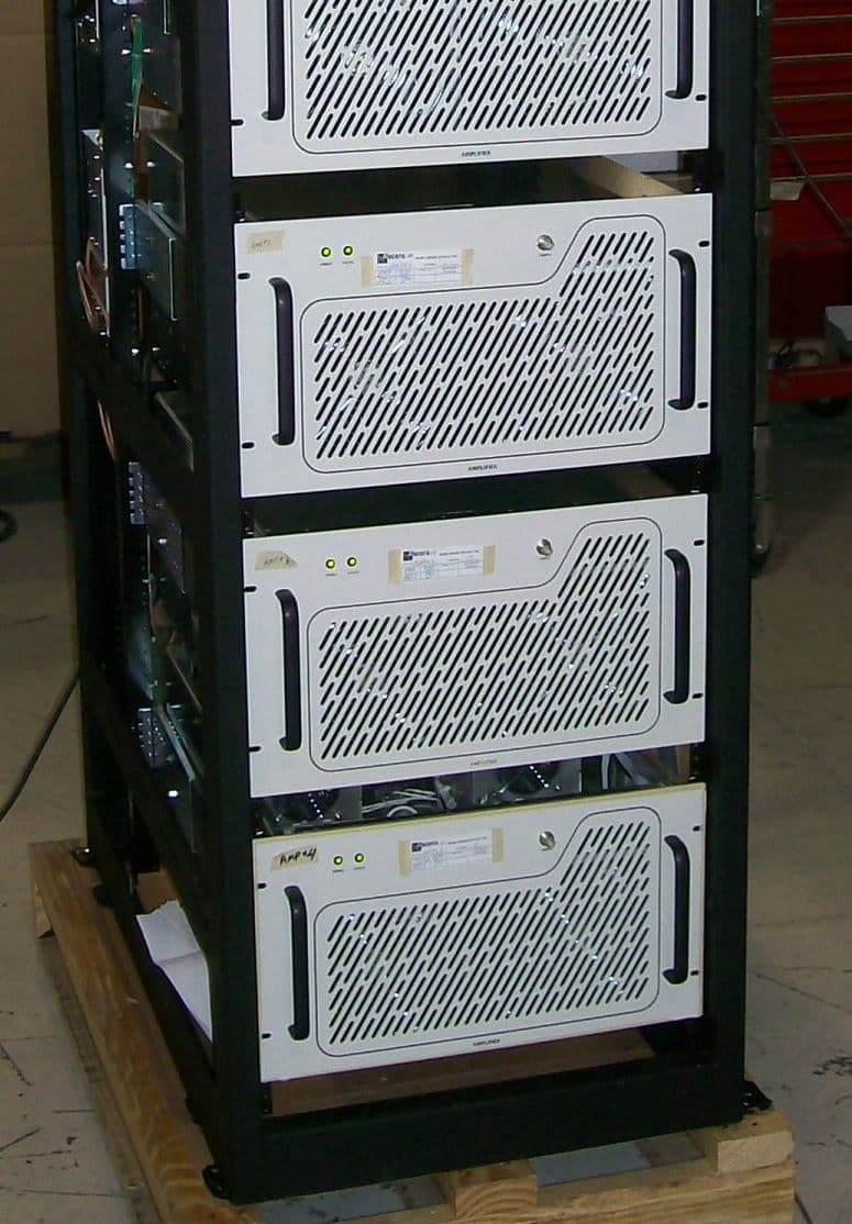
OUSCHV4TD
Jun 14, 20123000-Watt VHF Digital Transmitter
Equipment Class
TBC - Licensed Broadcast Station Transmitter
OUSCU0TD-5
Dec 14, 2011200 Watt UHF Digital Transmitter
Equipment Class
TBC - Licensed Broadcast Station Transmitter