OUSLL5ATC5-Watt, 1.6 GHz DVB-H Transmitter
UBS-Axcera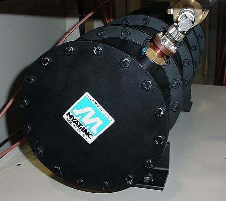
Click to zoom
Application Details
- Equipment Class
- TNB - Licensed Non-Broadcast Station Transmitter
- Date of Grant
- Oct 25, 2005
- Application Purpose
- Original Equipment
- Date of Application
- Sep 26, 2005
- Equipment Note
- 5-Watt, 1.6 GHz DVB-H Transmitter
- Frequency Range
- 1670.00000000 - 1675.00000000
- Company
- UBS-Axcera
- Country
- United States
Documents & Files
Document Text
Text extracted from the exhibit documents filed with the FCC. Open a document above to read the original.
Users Manual
ProTelevision Technologies A/S Marielundvej 16 DK-2730 Herlev Denmark PT 5780 DVB-T Modulator (ASIC) Instruction Manual Trade Mark of the DVB Digital Video Broadcasting Project PROTELEVISION technologies An ISO 9001 Certified Company PT 5780 DVB-T Modulator, Instruction Manual: Total number of pages: 95 Copyright 2003 ProTelevision Technologies A/S, Denmark All Rights Reserved Printed in Denmark 2003-08-25 Revision: 3.11 Publication number: 9499 493 12611 PT 5780 DVB-T Modulator ProTelevision Technologies Contents Instruction Manual Revision 3.11 i Contents 1 SAFETY..................................................................................................................1-1 1.1 INTRODUCTION........................................................................................................1-1 1.2 SAFETY PRECAUTIONS.............................................................................................1-1 1.3 CAUTION AND WARNING STATEMENTS........................................................................1-1 1.4 IMPAIRED SAFETY PROTECTION.................................................................................1-2 1.4.1 Technical Specifications..............................................................................1-2 1.4.2 Equipment Ratings......................................................................................1-3 1.5 ELECTROSTATIC SENSITIVE DEVICES..........................................................................1-3 1.6 SYMBOLS...............................................................................................................1-4 2 INTRODUCTION AND APPLICATIONS...........................................................2-1 2.1 APPLICATIONS.........................................................................................................2-1 2.1.1 Block Diagram (PT 5780 features)................................................................2-3 2.2 TRANSMISSION MODES SUPPORTED...........................................................................2-3 2.3 TRANSPORT STREAM INPUTS.....................................................................................2-4 2.4 ALARM CIRCUITS.....................................................................................................2-6 2.5 OPERATION............................................................................................................2-6 2.6 FREQUENCY REFERENCES........................................................................................2-6 2.7 TEST FACILITIES......................................................................................................2-7 3 INSTALLATION.....................................................................................................3-1 3.1 INITIAL INSPECTION..................................................................................................3-1 3.2 SAFETY INSTRUCTION..............................................................................................3-1 3.2.1 Earthing......................................................................................................3-1 3.3 MAINS VOLTAGE CORD AND FUSES............................................................................3-1 3.4 RACK MOUNTING.....................................................................................................3-2 3.5 CLEANING..............................................................................................................3-2 3.6 CONFIGURATION......................................................................................................3-3 3.6.1 Wiring schemes for RS 232 (handshake not implemented)............................3-3 3.6.2 Alarms........................................................................................................3-3 3.6.3 Mute...........................................................................................................3-4 3.6.4 Reset.........................................................................................................3-4 3.7 ACCESS TO AND REPLACEMENT OF PARTS..................................................................3-4 3.7.1 Safety.........................................................................................................3-4 3.7.2 Access to the Units......................................................................................3-4 4 OPERATING INSTRUCTIONS...........................................................................4-1 4.1 FRONT PANEL.........................................................................................................4-1 4.1.1 Front Panel Indicators..................................................................................4-1 4.1.2 Front Panel Controls (The menu system)......................................................4-1 4.1.3 Front Panel Display.....................................................................................4-3 4.2 REAR PANEL...........................................................................................................4-3 4.2.1 Rear Panel Connections..............................................................................4-3 4.3 MENU SYSTEM – DESCRIPTION AND OPERATION..........................................................4-5 4.3.1 Power Up...................................................................................................4-5 4.3.2 Operating Menu System Chart.....................................................................4-6 4.3.3 Status Menu System...................................................................................4-6 4.3.3.1 Description of Status Display Windows...........................................4-7 PT 5780 DVB-T Modulator ProTelevision Technologies Contents Instruction Manual Revision 3.11 ii 4.3.4 Configuration Menu System.......................................................................4-11 4.3.4.1 Top-level configuration menu access....…
Text truncated - open the document above for the full version.
Users Manual
INSTRUCTION MANUAL (Preliminary) INNOVATOR LX SERIES 1.67 GHz 5W DVB-H TRANSMITTER AXCERA, LLC 103 FREEDOM DRIVE P.O. BOX 525 LAWRENCE, PA 15055-0525 USA (724) 873-8100 • FAX (724) 873-8105 www.axcera.com • [email protected] 1.67 GHz 5 Watt Single Output Transmitter Chapter 1, Introduction LL5ATC, Rev. 0 1-1 Chapter 1 Introduction 1.1 Manual Overview This manual provides descriptions of the transmitter and associated equipment along with the set up and operating procedures. It is important that you read all of the instructions, especially the safety information in this chapter, before you begin operating the unit. This instruction manual is divided into five chapters and supporting appendices. Chapter 1, Introduction, contains information on the assembly numbering system used in the manual, safety, contact information, return procedures, and warranties. Chapter 2, System Description, includes overview of entire transmitter system. Chapter 3, Circuit Descriptions, contains circuit level descriptions for boards and board level components in the transmitter. Chapter 4, Transmitter Tuning Procedure, provides information on adjusting the system for optimal operation. Appendix A contains system specifications. Appendix B contains Site Drawings. Appendix C contains a list of Modules and Site ID. Appendix D Site Acceptance Document. 1.2 Assembly Designators Axcera has assigned assembly numbers, Ax designations such as A1, where x=1,2,3...etc, to all assemblies, modules, and boards in the system. These designations are referenced in the text of this manual and shown on the drawings provided in the appendices. The cables that connect between the boards within a tray or assembly and that connect between the trays, racks and cabinets are labeled using Brady markers. Figure 1-1 is an example of a Brady marked cable. There may be as few as two or as many as four Markers on any one cable. These Brady markers are read starting furthest from the connector. If there are four Brady Markers, this marker is the transmitter number such as transmitter 1 or Transmitter 2. The next or the furthest Brady Marker is the rack or cabinet number on an interconnect cable or the board number within a tray. The next number on an interconnect cable is the Tray location or number. The Brady marker closest to the connector is the Jack or Connector number on an interconnect cable or the jack or connector number on the board within a tray. Figure 1-1 Brady Marker Identification Drawing 1.67 GHz 5 Watt Single Output Transmitter Chapter 1, Introduction LL5ATC, Rev. 0 1-2 1.3 Safety The 1.67 GHz transmitter systems manufactured by Axcera are designed to be easy to use and repair while providing protection from electrical and mechanical hazards. Please review the following warnings and familiarize yourself with the operation and servicing procedures before working on the transmitter system. Read All safety Instructions – All of the safety instructions should be read and understood before operating this equipment. Retain Manuals – The manuals for the transmitter should be retained at the transmitter site for future reference. Axcera provides two sets of manuals for this purpose; one set can be left at the office while one set can be kept at the site. Heed all Notes, Warnings, and Cautions – All of the notes, warnings, and cautions listed in this safety section and throughout the manual must be followed. Follow Operating Instructions – All of the operating and use instructions for the transmitter should be followed. Cleaning – Unplug or otherwise disconnect all power from the equipment before cleaning. Do not use liquid or aerosol cleaners. Use a damp cloth for cleaning. Ventilation – Openings in the cabinet and module front panels are provided for ventilation. To ensure the reliable operation of the driver/transmitter, and to protect the unit from overheating, these openings must not be blocked. Servicing – Do not attempt to service this product yourself until becoming familiar with the equipment. If in doubt, refer all servicing questions to qualified Axcera service personnel. Replacement Parts – When replacement parts are used, be sure that the parts have the same functional and performance characteristics as the original part. Unauthorized substitutions may result in fire, electric shock, or other hazards. Please contact the Axcera Technical Service Department if you have any questions regarding service or replacement parts. 1.4 Contact Information The Axcera Field Service Department can be contacted by phone at (724) 873- 8100 or by fax at (724) 873-8105. Before calling Axcera, please be prepared to supply the Axcera technician with answers to the following questions. This will save time and help ensure the most direct resolution to the problem. 1. What are the Customers’ Name and call letters? 2. What are the model number and type of transmitter? 3. How long has the transmitter been on the air? (Approximately when was the transmitter installed.) 4. What are the symptoms being exhibited by the transmitter? Include the current control/power supply LCD readings and the status of LEDs on the front panels of the modules. If possible, include the control/power supply LCD readings before the problem occurred. 1.5 Material Return Procedure To insure the efficient handling of equipment or components that have been returned for repair, Axcera requests that each returned item be accompanied by a Material Return Authorization Number (MRA#). The MRA# can be obtained from any Axcera Field Service Engineer by contacting the Axcera Field Service Department at (724) 873-8100 or by fax at (724) 873-8105. This procedure applies to all items sent to the Field 1.67 GHz 5 Watt Single Output Transmitter Chapter 1, Introduction LL5ATC, Rev. 0 1-3 Service Department regardless of whether the item was originally manufactured by Axcera. When equipment is sent to the field on loan, an MRA# is included with the unit. The MRA# is intended to be used when th…
Text truncated - open the document above for the full version.
External Photos
Axcera-LL5ATC FCC Type Acceptance Report External Photos July 2005 2-1 2. EXTERNAL PHOTOS 2.1 Front view, complete LL5ATC Transmitter w/Pro-Television Modulator, Model PT-5780 2.2 Rear view, complete Axcera-LL5ATC Transmitter, w/Pro-Television Modulator, Model PT-5780 Axcera-LL5ATC FCC Type Acceptance Report External Photos July 2005 2-2 2.3 Rear view, Bandpass Filter Axcera-LL5ATC FCC Type Acceptance Report External Photos July 2005 2-3 2.4 Front view, Pro-Television DVB-T Modulator, Model PT-5780 2.5 Rear view, Pro-Television DVB-T Modulator, Model PT-5780
ID Label/Location Info
Axcera-LL5ATC FCC Type Acceptance Report ID Label/Location Info July 2005 1-1 1. ID LABEL/LOCATION INFO 1.1 Rear Panel FCC Label 1.2 Rear Panel Manufacturer’s Label Axcera-LL5ATC FCC Type Acceptance Report ID Label/Location Info July 2005 1-2 1.3 Rear view, complete Axcera-LL5ATC Transmitter with FCC Label and Manufacturer’s Label
Internal Photos
Axcera-LL5ATC FCC Type Acceptance Report Internal Photos July 2005 6-1 6. INTERNAL PHOTOS 6.1 Front view – Chassis Assembly (Driver) 6.2 Side view - Metering Assembly (Driver) Axcera-LL5ATC FCC Type Acceptance Report Internal Photos July 2005 6-2 6.3 Side view - Upconverter Assembly (Driver) 6.4 Side view - Control / Power Supply Assembly (Driver) Axcera-LL5ATC FCC Type Acceptance Report Internal Photos July 2005 6-3 6.5 Side view - Power Amplifier Assembly (Driver)
Operational Description
Axcera-LL5ATC FCC Type Acceptance Report Operational Description July 2005 8-1 8. OPERATIONAL DESCRIPTION - MODEL Axcera-LL5ATC 8.1 General Description The LL5ATC is a complete 5-watt solid-state, DVB-H transmitter. It operates at a nominal output power of 5 watts (average). 8.2 Technical Specifications Type of Emission ....................................................................5M00W7D Frequency Range.................................................1670 MHz to 1675 MHz Output Power Rating .......................................................5 watts average 8.3 Performance Specifications Operating Frequency Range .................................. 1670 MHz to 1675 MHz RF output - Nominal: Power .................................................................5 watts average Impedance .................................................................... 50 ohms Connector ............................................................................ ”N” Standard ....................................................................................DVB-H Modulation..........................................................QPSK, 16 QAM, 64 QAM IFFT Length .......................................................................... 2K, 4K, 8K Protection Interval .................................................1/4, 1/8, 1/16 & 1/32 Code Rate ........................................................ 1/2, 2/3, 3/4, 5/6, & 7/8 Frequency Stability .................................................................... 1 x 10 -6 w/Precise Frequency Option............................................. 1 x 10 -10 Regulation of RF Output Power .......................................................... 3% Shoulder Attenuation ..................................................... -35 dB or better Phase Noise .........................................................<-85 dBc/Hz @ 100 Hz Inputs .............................................................. Serial data inputs (ASI), Parallel Data Input (SPI), High Priority, LVDS Electrical Requirements Power Line Voltage................................................... 230 volts, 50/60 Hz Power Consumption ................................................................ 425 watts Environmental Maximum Altitude ..................................................................8,500 feet Operational Temperature Range ......................................... -5°C to +50°C Axcera-LL5ATC FCC Type Acceptance Report Operational Description July 2005 8-2 Mechanical Dimensions: Width ..........................................................................22 inches Depth ..........................................................................34 inches Height..........................................................................55 inches Weight ............................................................................ 300 lbs Axcera-LL5ATC FCC Type Acceptance Report Operational Description July 2005 8-3 8.4. System Overview The LL5ATC (1306313) is made up of the trays listed in Table 8-1. Table 8-1. LL5ATC Major Trays and Assemblies MAJOR ASSEMBLY DESIGNATOR TRAY/ASSEMBLY NAME DRAWING NUMBER A1 DVB-T Modulator Model PT-5780 A2 Driver Assembly 1305021 8.4.1 DVB-T Modulator Tray/Driver Tray The LL5ATC is a complete DVB-H transmitter capable of operating at an output power of 5 watts (average). Functionally, the LL5ATC is comprised of a modulator (Pro-Television, Model 5780) and driver tray. The 36 MHz IF signal from the modulator is applied to the input of the driver/amplifier which provides spectral shaping of the IF signal in accordance with Occupied Bandwidth requirements of the Rules and Regulations. The modulator receives a serial bit stream, consisting of multiplexed MPEG-2 transport streams, translates the signal to a Quadrature Amplitude Modulated (QAM) format, converts the digital information to analog, and modulates the signal to IF (36 MHz). The modulator tray’s IF output is routed to the driver/amplifier tray for IF signal processing, upconversion to the 1670-1675 MHz band, and final amplification. The driver/amplifier tray utilizes ALC circuitry for automatic level control of the output signal to maintain a constant power level. Both modulator and driver/amplifier trays are 19-inch rack mount assemblies and can be supplied with or without a cabinet. Both trays are supplied complete with cables and cabinet slides. The output of the DVB-T Modulator Tray is connected to the Driver Tray (driver). 8.4.1.1 Metering Module (Driver) This assembly has circuitry that is used to measure the average power of up to four RF inputs. Each RF input is split on the Metering Board (1304922), with some of the signal being applied to an average power detector, and the rest of the signal sent to the front panel sample to allow the operator to monitor the RF signal with his own test equipment. The output of each detector is sent to the transmitter's system control via the Backplane that the assembly plugs into. 8.4.1.2 L.O. / Upconverter Module (Driver) This assembly converts either one or two separate 36 MHz IF signals to either one or two RF outputs at a frequency of 1670-1675 MHz. It contains an Upconverter Control board (1304780), an LO Generator board (1304940) and either one or two Upconverter boards (1304929). The description below is for one half of the upconverter. The IF and upconverter paths can be duplicated to provide two outputs when needed. The second IF path is always present, but not used in single output upconverters. A second Upconverter board is added for dual output transmitters. An IF Signal centered at 36 MHz at a level of 0 dBm average is applied to the Upconverter Control board. A sample is applied to a peak detector, which checks for the Axcera-LL5ATC FCC Type Acceptance Report Operational Description July 2005 8-4 presence of an IF input. If the input is not present, an alarm is generated and displayed on the module's front panel, and is also n…
Text truncated - open the document above for the full version.
Parts List/Tune Up Info
Axcera-LL5ATC FCC Type Acceptance Report Parts List/Tune-up Info July 2005 7-1 7. PARTS LIST/TUNE-UP INFO 7.1 Parts List The transmitter, can be subdivided as follows: DVB-T Modulator Tray (See modulator manual for tune-up info) Driver Tray: Metering Module L.O. / Upconverter Module Control & Monitoring / Power Supply Module • Power Amplifier Module 7.2 Tune-up Information The LL5ATC transmitter was aligned at the factory and should not require additional alignments to achieve normal operation. 7.2.1 Setting up Manual Gain Turn the Manual Gain Pot on the front panel of the Upconverter full CCW. Switch the Auto/Manual Gain Switch to the left (Manual) Gradually turn the manual gain pot clockwise while monitoring the output power on a power meter connected to the output of the transmitter is 100%. 7.2.2 Power Calibration Connect a Power meter to the output sample of the transmitter. Note the Insertion loss from the output to the sample port. Enter that offset into the Power meter's Offset Rel function, and set the reference frequency to 1670 MHz. Navigate to the Transmitter Setup Menu on the System Controller and enter that menu. Scroll down until the A Output Power Adjust screen is reached. Use the Up/down Arrows to adjust power to desired output power. Scroll down to the A Output Power Cal screen. Adjust Power Calibration until meter reads 100%. 7.2.3 Setting up AGC Step 1: Navigate to the Transmitter Setup Menu on the System Controller and enter that menu. Scroll down until the A Output Power Adjust screen is reached. Use the Up/down Arrows to adjust power to 100%. (Power Calibration must have been done first) Step 2: Scroll down further to Inner Loop A Gain menu is reached. Increase the Inner Loop Gain while watching the output power. Keep increasing until the output power begins to drop. Note the setting on Inner Loop gain, and reduce the setting by 10%. Example: The Inner Loop Gain setting where power begins to move is 210. Reduce the setting by 21 to 189. Axcera-LL5ATC FCC Type Acceptance Report Parts List/Tune-up Info July 2005 7-2 NOTE: If adjusting the Inner Loop gain causes the power to rise immediately, then the AGC has been running on Inner Loop Gain, not Outer Loop Gain. Go back to step 1, reduce the power to 50%, then go to step 2 and reduce the Inner Loop A Gain until the power stops rising or you have reached 110%, whichever comes first. If you reach 110%, go. Repeat as many times as you need to until the Inner Loop does not affect power. Once the power stops rising when Inner Loop Gain Continue to lower the Inner Loop gain further by 20%, then go back to step 1 a final time. Bring the power back up to 100% and go to step 2 one final time. 7.2.4 Overdrive Go to the Transmitter Setup Menu, and scroll down to the A Output Power Adjust screen. Turn the Output power up to 10%. Then scroll down to the A Overdrive screen and lower the Overdrive setting until power just starts to drop. Go back to the A Output Power Adjust screen and reduce the power to 100%. 7.2.5 Reflected Power Calibration Connect a Power meter to the Reflected sample of the transmitter. Note the Insertion loss from the output to the sample port. Enter that offset into the Power meter's Offset Rel function, and set the reference frequency to 1670 MHz. Navigate to the Transmitter Setup Menu on the System Controller and enter that menu. Scroll down until the A Output Power Adjust screen is reached. Use the Up/down Arrows to adjust power to 20% of the desired output power. Swap the forward and reflected power cables on the transmitter's output coupler. Scroll down to the A Output Power Cal screen. Adjust Power Calibration until meter reads 20%. Return cables to their correct position. Go back to the A Output Power Adjust screen and return Output power to 100%. 7.2.6 Bandpass Filter Assembly The Bandpass Filter Assembly is tuned to reject unwanted distortion products generated when the signals are diplexed and also during the amplification process. The Bandpass Filter is factory tuned to the proper bandwidth and should not need tuned. If you think tuning is needed consult Axcera Field Support Department before beginning the adjustment. 7.2.7 Linear and Non-linear Pre-correction set-up Refer to the Pro-television manual for this procedure. The Transmitter is ready for normal operation. This completes the detailed alignment procedures for the LL Series transmitter.
Schematics
Axcera-LL5ATC FCC Type Acceptance Report Schematics July 2005 3-1 3. SCHEMATICS The schematics for the Axcera-LL5ATC system are provided as separate PDF files.
Schematics
5 5 4 4 3 3 2 2 1 1 DD CC BB AA UC_IF_INPUT_A SYSTEM_10_MHz_INPUT System_+12Vdc_C5 UC_IF_INPUT_B UC_INTERLOCK RMT_RF_SYSTEM_INTERLOCK B System_Serial+ SYSTEM_FORWARD_POWER_A SYSTEM_FORWARD_POWER_A SYSTEM_10_MHz_INPUT RMT_AUX_I/O_1 System_-12Vdc_C1 UC_IF_INPUT_A System_-12Vdc_C1 RMT_RF_SYSTEM_INTERLOCK A UC_MUTE_B_CMD System_+12Vdc_C6 UC_INTERLOCK System_+12Vdc_C6 System_-12Vdc_C1 System_Serial- SYSTEM_10_MHz_OUTPUT SYSTEM_10_MHz_OUTPUT System_-12Vdc_C1 UC_AGC_2_REF_B_XMTR UC_AGC_1_REF_A_XMTR System_+12Vdc_C5 System_Serial+ System_+12Vdc_C6 SYSTEM_REFLECTED_POWER_A UC_AGC_2_REF_B_XMTR RF_METERING_INTERLOCK RMT_AUX_I/O_2 UC_AGC_1_REF_B_XMTR System_-12Vdc_C1 System_+12Vdc_C5 SYSTEM_REFLECTED_POWER_B System_Serial- RMT_AUX_I/O_2 System_-12Vdc_C1 UC_AGC_2_REF_A_XMTR System_+12Vdc_C4 System_+12Vdc_C6 UC_MUTE_A_CMD System_-12Vdc_C1 System_+12Vdc_C4 RMT_SET_TO_OPERATE_CMD System_Serial- UC_AGC_1_REF_B_XMTR System_Serial+ UC_IF_INPUT_B System_+12Vdc_C5 RMT_TRANSMITTER_STATE UC_AGC_1_REF_A_XMTR UC_AGC_2_REF_A_XMTR SYSTEM_FORWARD_POWER_B UC_MUTE_A_CMD SYSTEM_REFLECTED_POWER_B System_+12Vdc_C4 System_-12Vdc_C1 System_-12Vdc_C1 System_+12Vdc_C5 RMT_TRANSMITTER_STATE SYSTEM_FORWARD_POWER_B SYSTEM_REFLECTED_POWER_A UC_MUTE_B_CMD RMT_RF_SYSTEM_INTERLOCK A RMT_SET_TO_STANDBY_CMD RMT_SET_TO_OPERATE_CMD RMT_RF_SYSTEM_INTERLOCK B RMT_INTERLOCK RMT_INTERLOCK RMT_INTERLOCK_ISOLATED_RTN RMT_AUX_I/O_1 RMT_INTERLOCK_ISOLATED_RTN RMT_SET_TO_STANDBY_CMD System_+12Vdc_C3 System_+12Vdc_C3 System_+12Vdc_C3 System_+12Vdc_C3 System_+12Vdc_C3 System_+12Vdc_C3 System_+12Vdc_C3 RF_METERING_INTERLOCK UC_AGC_1_REF_B_XMTR System_Serial- System_Serial+ AMP_B_INTERLOCK System_+12Vdc_C3 SCADA_232_B_IN SCADA_232_B_OUT SCADA_232_A_OUT SCADA_485- SCADA_232_B_IN SCADA_485- SCADA_485- SCADA_232_B_OUT SCADA_232_A_IN UC_AGC_2_REF_A_XMTR System_Serial+ System_Serial- UC_AGC_2_REF_B_XMTR SCADA_485+ System_-12Vdc_C2 System_-12Vdc_C2 SCADA_485+ System_-12Vdc_C2 System_-12Vdc_C2 SCADA_485+ R MT_AUX_I/O_[1..2] System_-12Vdc_C2 AMP_B_INTERLOCK SCADA_485+ SCADA_485- SCADA_485+ SCADA_485- SCADA_232_A_IN SCADA_232_A_OUT Axcera REV ECO DATEAPV TITLE THIS PRINT IS THE PROPERTY OF AXCERA, IT SHALL NOT BE COPIED WITHOUT PERMISSION MATERIAL FINISH DWN CHK REL SCALESHEET REV REV ECO DATE APV DWG. NO. --- ----- ----- 1304893 A0 SCH, BACKPLANE BOARD, 1670 (1304891) DB10/11/04 D1 OF 1 10/13/04 DB 10/13/04DB Upconverter SCADA (Input / Loop-Thru) EXTERNAL 10 MHz INPUT IF INPUT A KEY SYSTEM 10 MHz OUTPUT Auto_Test_1 Auto_Test_2 Control KEY RTN Metering Module IF INPUT B RTN +12V -12V INTERLOCK SERIAL + SERIAL - UC AGC #1 REF DRIVER POWER AMP B INTERFACE SCADA (Input / Loop-Thru) System RS-485 Serial RELATED PART NUMBERS: ASSY: 1304891 PCB: 1304898 SCH: 1304893 Leave hole for Cable Leave hole for Cable Leave hole for Cable Leave hole for Cable Leave hole for Cable Leave hole for Cable J41 16A 16B 16C 17A 17B 17C 13A 13C 15A 15C 14B 19B 18A 18C 20A 20C 15B 13B 18B 19A 19C 20B 14A 14C 1A 1C 2B3A 3C 4A 4C5B 6A 6C 7A 7C 9A 9C 8B 10A 10C 12A 12C 11B 22B 25B 28B 31B 21A 21C 23A 23C 24A 24C 26A 26C 27A 27C 29A 29C 30A 30C 32A 32C TB30 1 2 3 4 5 6 7 8 9 10 11 12 13 14 15 16 17 18 C6 12pF GND GND J35 95123-2881 1 2 3 4 5 6 7 8 9 10 C7 12pF J44B 1B 2B 3B 4B 5B 6B 7B 8B 9B 10B 11B 12B 13B 14B 15B 16B 17B 18B 19B 20B 21B 22B 23B 24B 25B 26B 27B 28B 29B 30B 31B 32B C10 12pF C3 12pF C8 12pF C4 12pF C9 12pF J44A 1A 2A 3A 4A 5A 6A 7A 8A 9A 10A 11A 12A 13A 14A 15A 16A 17A 18A 19A 20A 21A 22A 23A 24A 25A 26A 27A 28A 29A 30A 31A 32A J21BNC J11BNC C1 .001 C11 12pF J42 16A 16B 16C 17A 17B 17C 13A 13C 15A 15C 14B 19B 18A 18C 20A 20C 15B 13B 18B 19A 19C 20B 14A 14C 1A 1C 2B3A 3C 4A 4C5B 6A 6C 7A 7C 9A 9C 8B 10A 10C 12A 12C 11B 22B 25B 28B 31B 21A 21C 23A 23C 24A 24C 26A 26C 27A 27C 29A 29C 30A 30C 32A 32C L1 .27uH J10BNC J44C 1C 2C 3C 4C 5C 6C 7C 8C 9C 10C 11C 12C 13C 14C 15C 16C 17C 18C 19C 20C 21C 22C 23C 24C 25C 26C 27C 28C 29C 30C 31C 32C GND GND J36 95123-2881 1 2 3 4 5 6 7 8 9 10 J22BNC C5 12pF C2 12pF J46 1 2 3 4 5 6 7 8 9 10 GND GND J37 95123-2881 1 2 3 4 5 6 7 8 9 10 5 5 4 4 3 3 2 2 1 1 DD CC BB AA +5Vanalog +5Vanalog +5Vanalog +5Vanalog +5Vanalog +5Vanalog +5Vanalog +5Vanalog +12V +5Vanalog +12V Fwd A Metering Refl A Metering Fwd B Metering Refl B Metering Fwd B Metering Refl B Metering Fwd A Metering Refl A Metering Axcera REV ECO DATEAPV TITLE THIS PRINT IS THE PROPERTY OF AXCERA, IT SHALL NOT BE COPIED WITHOUT PERMISSION MATERIAL FINISH DWN CHK REL SCALESHEET REV REV ECO DATE APV DWG. NO. --- ----- ----- 1304923 A0 SCH, LL METERING BOARD (1304922) DB 10/15/04 D1 OF 1 10/18/04 DB 10/18/04 DB (TOP SIDE) FWD A METERING FWD A CAL. FWD A SAMPLE (FP) REFL A CAL (FP) (TOP SIDE) REFL A METERING FWD B CAL FWD B SAMPLE (FP) (TOP SIDE) FWD B METERING REFL B CAL REFL B SAMPLE (FP) (TOP SIDE) REFL B METERING REFL A SAMPLE FORWARD SAMPLE A REFLECTED SAMPLE A FORWARD SAMPLE B REFLECTED SAMPLE B SYSTEM FWD POWER A SYSTEM RFLD POWER A SYSTEM FWD POWER B SYSTEMRFLD POWER B +12V +12V +12V -12V -12V -12V RTN RTN RTN RTN RTN RTN SYSTEM SERIAL + SYSTEM SERIAL - METERING INTERLOCK TP4 U7 AD8361ARM VPOS 1 IREF 2 RFIN 3 PWDN 4 COMM 5 FLTR 6 VRMS 7 SREF 8 C32 100pF R25 10K CW 3 2 1 + C5 10 35V L4 .47uH C3 .01 C29 .01 R14 100 C1 100pF R16 2.2K R6 2.2K R8 200 C19 100pF R33 150 R39 200 R24 100 R18 200 R26 2.2K J2 SMA R17 150 C25 100pF C27 100pF R32 75 C12 100pF L6 150 nH R28 200 TP2 R27 150 U4 AD8361ARM VPOS 1 IREF 2 RFIN 3 PWDN 4 COMM 5 FLTR 6 VRMS 7 SREF 8 C20 100pF + - U6B LM258D 5 6 7 4 8 TP3 C16 .01 U5 AD8361ARM VPOS 1 IREF 2 RFIN 3 PWDN 4 COMM 5 FLTR 6 VRMS 7 SREF 8 C28 .01 C26 100pF R9 200 R4 100 U2 AD8361ARM VPOS 1 IREF 2 RFIN 3 PWDN 4 COMM 5 FLTR 6 VRMS 7 SREF 8 R13 150 R19 200 C23 .01 J3 SMA C2 .01 + - U3A LM258D 3 2 1 4 8 R40 75 R1 2.2K C24 .01 C13 100pF R23 150 C11 100pF R29 200 R12 75 L2 150 nH R31 2.2K C4 .01 C10 100pF + C17 47 20V R10 75 C21 100pF R5 10K CW 3 2 1 TP1 R22 75 C9 100pF C6 .1 R7 150 L5 150 nH + - U3B LM258D 5 6 7 4 8 R35 10K CW 3 2 1 C15 .01 J4 SMA C8 100pF + - U6A LM…
Text truncated - open the document above for the full version.
Test Report
FCC TYPE ACCEPTANCE REPORT LL5ATC 5 WATT DVB-H TRANSM…
Text truncated - open the document above for the full version.
Contact Information
Applicant
David Hewitt(Engineering Manager)
Technical Contact
AxceraDavid W Brooking
[email protected]724-873-8100
103 Freedom Drive · Lawrence, Pennsylvania · United States
Non-Technical Contact
AxceraJames C Mounts
[email protected]724-873-8100
Technical Specifications
| # | Rule Parts | Frequency Range | Power Output | Emission | Tolerance |
|---|---|---|---|---|---|
| 1 | 27 | 1.67 GHz - 1.68 GHz | 5 W | 5M00W7D | 1672.5000000000 Hz |
Other Applications from UBS-Axcera

OUSCU0TD-5-UBS
Mar 27, 2014200W UHF Digital Transmitter
Equipment Class
TBC - Licensed Broadcast Station Transmitter
OUSCL1TC-4
Sep 17, 2013400-Watt, 1.6 GHz DVB-H Transmitter
Equipment Class
TNB - Licensed Non-Broadcast Station Transmitter
OUSCLV2TD-4
Aug 22, 2013Low Band VHF Digital Broadcast Transmitter
Equipment Class
TBC - Licensed Broadcast Station Transmitter
OUSCHV4TD
Jun 14, 20123000-Watt VHF Digital Transmitter
Equipment Class
TBC - Licensed Broadcast Station Transmitter
OUSCU0TD-5
Dec 14, 2011200 Watt UHF Digital Transmitter
Equipment Class
TBC - Licensed Broadcast Station Transmitter