OUV900L8TXMachine Remote Control TX
Magnetek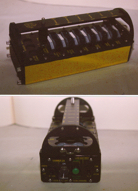
Click to zoom
Application Details
- Equipment Class
- DXX - Part 15 Low Power Communication Device Transmitter
- Date of Grant
- Feb 10, 2000
- Application Purpose
- Original Equipment
- Date of Application
- Jan 19, 2000
- Equipment Note
- Machine Remote Control TX
- Frequency Range
- 903.30000000 - 921.30000000
- Company
- Magnetek
- Country
- United States
Documents & Files
Document Text
Text extracted from the exhibit documents filed with the FCC. Open a document above to read the original.
Test Report
NATIONAL CERTIFICATION LABORATORY 8370 Court Avenue, Suite B-1 Ellicott City MD 21043 (410) 461-5548 FCC REPORT OF RADIO INTERFERENCE for Enrange #5 Four Coins Drive Canonsburg, PA 15317 FCC ID: OUV900L8TX January 13, 2000 TABLE OF CONTENTS Application Form 731 Label Format 1.0 Introduction 1.1 Summary 2.0 Description of Equipment Under Test (EUT) 3.0Test Configuration 4.0 Conducted Emissions Scheme 5.0 Radiated Emissions Scheme TABLES Table 1.Support Equipment Table 2.Measurement Equipment EXHIBITS Exhibit 1.EUT Photographs Exhibit 2. User Manual Exhibit 3.Schematics NCL PROJ.# ENRANGE0529-TX FCC ID #: OUV900L8TX 2 1.0 Introduction This report has been prepared on behalf of Enrange to support the attached Application for Certification of a Part 15 intentional Radiator. The Equipment Under Test was the EnrangeLAG360TX Radio Transmitter . Radio-Noise Emissions tests were performed according toANSI C63.4-1992 "Methods of Measurement of RFI from Low-Voltage Electronic Equipment in the Range of 9 KHz - 40 GHz" . The measuring equipment conforms to ANSI C63.2 Specifications for Electromagnetic Noise and Field Strength Instrumentation. Testing was performed at National Certification Laboratory in Ellicott City, MD. Site description and site attenuation data have been placed on file with the FCC's Sampling and Measurements Branch. FCC acceptance was granted on May 26, 1993. 1.1 Summary The EnrangeLAG360TX Radio Transmittercomplies with the Part 15.249 Radio Limits for operation within the band 902-928 MHz of an Intentional Radiator. 2.0 Description of Equipment Under Test (EUT) The EUT Features: FEATURES FREQUENCY LED Indicators 903.3-921.3 MHz RF Module Design PCM Encoding Batttery Powered Only Solenoid Switching Function For Hydraulic Equipment Internal Whip Antenna FCC ID #: OUV900L8TX 2 3.0 Test Configuration The EUT was setup on the test table in a manner which follows the general guidelines of ANSI C63.4, Section 6 "General Operating Conditions and Configurations" . The EUT was configured in 3 orthogonal positions to determine the maximum RF level at each emission frequency. The data tables give the EUT postion designation that produces worst-case field strength, in an X, Y, Z system. This is described below: 4.0 Conducted Emissions Scheme The EUT is powered by battery only. FCC ID #: OUV900L8TX 3 5.0 Radiated Emissions Scheme The EUT was initially scanned in the frequency range 30 to 9213 MHz indoors, at a distance of 1 meter to determine its emissions profile. The EUT was then placed on an 80 cm high 1 X 1.5 meter non-conductive motorized turntable for radiated testing on the 3- meter open area test site. The emissions from the EUT are measured continuously at every azimuth by rotating the turntable. Waveguide horn and log periodic broadband antennas are mounted on an antenna mast to determine the height of maximum emissions. The height of the antenna is varied between 1 and 4 meters. Cables are varied in position to produce maximum emissions. Both the horizontal and vertical field components are measured. The output from the antenna is connected to the input of the spectrum analyzer. The detector function is set toPEAKas required. The resolution bandwidth of the spectrum analyzer system is set at 120 kHz, for measurements in the range 30 MHz – 960 MHz, and 1 MHz for measurements in the range of 960 MHz – 9 GHz, with all post-detector filtering no less than 10 times the resolution bandwidth. All emissions within 20 dB of the limit are recorded in the data tables. To convert the spectrum analyzer reading into a quantified E-field level to allow comparison with the FCC limits, it is necessary to account for various calibration factors. These factors include cable loss (CL) and antenna factors (AF). The AF/CL in dB/m is algebraically added to the Spectrum Analyzer Voltage in db μ Vto obtain the Radiated Electric Field in dB μ V/m. This level is then compared with the FCC limit. Example: Spectrum Analyzer Volt: VdBuV Composite Factor: AF/CLdB/m Electric Field: EdB μ V/m = VdB μ V + AF/CLdB/m Linear Conversion: EuV/m = Antilog (EdB μ V/m/20) FCC ID #: OUV900L8TX 4 FCC RADIATED EMISSIONS DATA CLIENT:ENRANGE EUT:LAG360TX TUNING FREQ:921.30 MHZ 3-METER TEST PEAK AVG FREQPOL SPEC A AF/CLAMPE-FIELDE-FIELDLIMITMRGN MHzdBuVdB/mGAINdBuV/muV/muV/mdB 921.30 H 61.024.0085.017782.850000.0-9.0 1842.60 H 51.027.0-3048.0251.2500.0-6.0 2763.90 V 43.031.0-3044.0158.5500.0-10.0 3685.20 H 42.033.0-3045.0177.8500.0-9.0 4606.50 V 43.034.0-3047.0223.9500.0-7.0 5527.80 V 40.035.0-3045.0177.8500.0-9.0 6449.10 V 42.036.0-3048.0251.2500.0-6.0 7370.40 H 38.037.0-3045.0177.8500.0-9.0 8291.70 H 35.037.0-3042.0125.9500.0-12.0 9213.00 V 36.038.0-3044.0158.5500.0-10.0 TEST ENGINEER __________________________DATE___________ STEVE DAYHOFF FCC ID #: OUV900L8TX 5 FCC RADIATED EMISSIONS DATA CLIENT:ENRANGE EUT:LAG360TX TUNING FREQ:912.30 MHZ 3-METER TEST PEAK AVG FREQPOL SPEC A AF/CLAMPE-FIELDE-FIELDLIMITMRGN MHzdBuVdB/mGAINdBuV/muV/muV/mdB 912.30 H 62.024.0086.019952.650000.0-8.0 1824.60 H 50.027.0-3047.0223.9500.0-7.0 2736.90 V 45.031.0-3046.0199.5500.0-8.0 3649.20 H 41.033.0-3044.0158.5500.0-10.0 4561.50 V 44.034.0-3048.0251.2500.0-6.0 5473.80 V 39.035.0-3044.0158.5500.0-10.0 6386.10 V 40.036.0-3046.0199.5500.0-8.0 7298.40 H 37.037.0-3044.0158.5500.0-10.0 8210.70 H 34.037.0-3041.0112.2500.0-13.0 9123.00 V 35.038.0-3043.0141.3500.0-11.0 TEST ENGINEER __________________________DATE___________ STEVE DAYHOFF FCC ID #: OUV900L8TX 6 FCC RADIATED EMISSIONS DATA CLIENT:ENRANGE EUT:LAG360TX TUNING FREQ:903.30 MHZ 3-METER TEST PEAK AVG FREQPOL SPEC A AF/CLAMPE-FIELDE-FIELDLIMITMRGN MHzdBuVdB/mGAINdBuV/muV/muV/mdB 903.30 H 62.024.0086.019952.650000.0-8.0 1806.60 H 52.027.0-3049.0281.8500.0-5.0 2709.90 V 45.031.0-3046.0199.5500.0-8.0 3613.20 H 43.033.0-3046.0199.5500.0-8.0 4516.50 V 43.034.0-3047.0223.9500.0-7.0 5419.80 V 38.035.0-3043.0141.3500.0-11.0 6323.10 V 40.036.0-3046.0199.5500.0-8.0 7226.40 H 37.037.0-3044.0158.5500.0-10.0 8129…
Text truncated - open the document above for the full version.
Contact Information
Applicant
Chris Dulin(Radio Product and Development Manager)
Technical Contact
National Certification LabSteve l Dayhoff
[email protected]410 461 5548
8370 Court Ave., Suite B-1 · Ellicott City, Maryland · United States
Non-Technical Contact
National Certification LabSteven L Dayhoff
[email protected]410 461 5548
Test Firm
National Certification LaboratoryBrian Haghtalab
Technical Specifications
| # | Rule Parts | Frequency Range | Power Output |
|---|---|---|---|
| 1 | 15C | 903.3 MHz - 921.3 MHz | - |
Other Applications from Magnetek
OUV01GTRF
Jun 13, 2001TR120 Remote TX
Equipment Class
DXX - Part 15 Low Power Communication Device Transmitter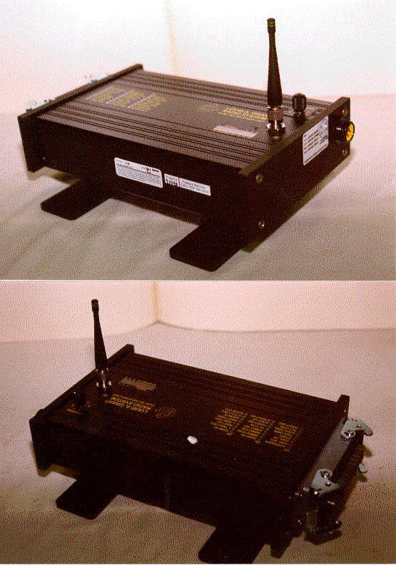
OUV900L8RX
Jan 27, 2000Control Receiver
Equipment Class
CYY - Communications Receiver used w/Pt 15 Transmitter