OV9-WIRE1900MHz TRANSMITTER FOR WIRELESS IR REPEATER SYSTEM
Spyder Controls Corp.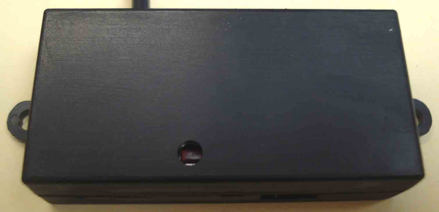
Click to zoom
Application Details
- Equipment Class
- DXT - Part 15 Low Power Transceiver, Rx Verified
- Date of Grant
- Aug 15, 2012
- Application Purpose
- Original Equipment
- Date of Application
- Aug 15, 2012
- Equipment Note
- 900MHz TRANSMITTER FOR WIRELESS IR REPEATER SYSTEM
- Frequency Range
- 903.40000000 - 923.80000000
- Company
- Spyder Controls Corp.
- Country
- Canada
Documents & Files
Document Text
Text extracted from the exhibit documents filed with the FCC. Open a document above to read the original.
Users Manual
Spyder Controls Corporation Defining Innovation and Reliability in System Control USER MANUAL FOR: ‘WIRE1’ WIRELESS INFRA-RED (IR) REPEATER SYSTEM DVD & SAT RF to IR IR to RF IR to RF IR to RF DESCRIPTION:The wireless IR Repeater system allows Infra-Red (IR) signals from Audio / Video (A/V) remote controls to be received in one location and wirelessly transmitted to another location, where the IR signal is then re-emitted. The system uses proven Radio Frequency (RF) technology that is used in numerous automotive security / alarm systems, ensuring reliable operation. BENEFITS: -COST EFFECTIVE - -WIRE REDUCTION - -SIMPLIFIED INSTALLATION - -NO CROSSTALK ISSUES - Similar or less cost than conventional ’wired’ IR Repeater systems Wiring and connector blocks between the IR Receivers and the IR Emitters is completely eliminated With over 50% of the wiring and connections removed completely A built-in signal filtering system eliminates IR crosstalk where multiple IR receivers are located in the same area Rev 1.1 07/06/2012page 1Specifications subject to change without notice Spyder Controls Corporation Defining Innovation and Reliability in System Control User Manual WIRE1 User Manual Rev 1.1 JULY 31, 2012page 1Specifications subject to change without notice RF Characteristics: - ISM band: - Base frequency: - Channel spacing: - Over-the-air data rate: - TX power: - Number of channels: 900MHz; 903MHz; 199.951172MHz; 249.756 Kbs; 0 dBm; 52. Operational Voltage Range:5to16VDC DESCRIPTION:The wireless IR Repeater system allows Infra-Red (IR) signals from Audio / Video (A/V) remote controls to be received in one location and wirelessly transmitted to another location, where the IR signal is then re-emitted. The system uses proven Radio Frequency (RF) technology that is used in numerous automotive security / alarm systems, ensuring reliable operation. FCC Statement: Industry Canada Statement: This device complies with part 15 of the FCC Rules. Operation is subject to the following two conditions: (1) This device may not cause harmful interference, and (2) this device must accept any interference received, including interference that may cause undesired operation. Changes or modifications not expressly approved by the party responsible for compliance could void the user's authority to operate the equipment. This device complies with Industry Canada licence-exempt RSS standard(s). Operation is subject to the following two conditions: (1) this device may not cause interference, and (2) this device must accept any interference, including interference that may cause undesired operation of the device. Cet appareil est conforme la norme d'Industrie Canada exempts de license RSS (s). Son fonctionnement est soumis aux deux conditions suivantes: (1) cet appareil ne peut pas provoquer d'interférences, et (2) cet appareil doit accepter toute interférence, y compris les interférences qui peuvent causer un mauvais fonctionnement de la appareil. This Class B digital apparatus complies with Canadian ICES-003. Cet appareil numérique de la classe B est conforme à la norme NMB-003 du Canada. _______________________________________________________________ MODEL: WIRE1 FCC ID: OV9-WIRE1 IC: 10245A-WIRE1 Spyder Controls Corporation Defining Innovation and Reliability in System Control WIRe Repeater (Receiver) LED Indicator IR Receiver Ground 12v* 0.5" 2.0" 2.18" 120.00° Programming Button Receiver Angle LED Indicator IR Receiver USB cable 0.5" 2.0" 2.18" Programming Button Receiver Angle 120.00° User Manual Rev 1.1 JULY 31, 2012page 2Specifications subject to change without notice Spyder Controls Corporation Defining Innovation and Reliability in System Control wIRe Repeater (Emitter) Emitter LEDs 12v Ground 0.5" 2.0" LED Indicator Emitter Angle Programming Button 120.00° Connector User Manual Rev 1.1 JULY 31, 2012page 3Specifications subject to change without notice Spyder Controls Corporation Defining Innovation and Reliability in System Control WIRE Channel Settings ActionWIRE ResponseIndicator Quick press* (once) 1. Enter the Transmit Learning Codes (TLC) state 2. Transmit "learn" packets 2 times per second LED flashes slow (1 time per second 1/4s ON, 3/4s OFF) Long press* 1. Increment RF channel 2. Returns to TLC state LED is ON for 1 sec Quick press (once) 1. Exit from TLC mode 2. Entering Main Operation mode LED stops flashing 2 Quick presses 1. Enter Listening Mode 2. Device ‘listens’ for an RF signal**. 3. Once an RF signal is received, the device learns (memorizes) that channel. 4. Device will automatically exit Listening Mode and resume normal operation. LED flashes FAST (2 times per second, 1/4s ON, 1/4s OFF) 2 Quick presses (while in Listening Mode) 1. Manually exit from Listening Mode 2. Revert to the channel it was on before this learning cycle started LED stops flashing Note: When in Listening Mode, a WIRE will only act on learn packets that contain its traffic-type byte. **The wIRe devices operate on 52 unique channels. When a wIRe device enters Learning Mode, it begins with the existing channel stored in memory and ‘listens’ for a matching RF signal for 1 second. If no matching signal is received within 1 second, the wIRe device increments up to the next channel and listens for 1 second and so on until a matching RF signal is received. It can take up to 52 seconds for a wIRe device to find a matching signal and learn / memorize it. * Long button press would be one that was for about 1 second. * Quick button press would be one that was for less than ½ second. User Manual Rev 1.1 JULY 31, 2012page 4Specifications subject to change without notice
ID Label/Location Info
Device Label and Location DEVICE LABELING REQUIREMENTS (FCC §2.925, §15.19 & IC RSS-GEN)
Test Report
Test Report Serial No.: 071712OV9-T1187-E15C Report Issue Date: Aug. 13, 2012 Measurement Date(s): July 30-31, 2012 Report Revision No.: Revision 1.0 FCC Rule Part(s): 47 CFR §2; §15.249 FCC Test Firm Reg. No.: Accredited IC Standard(s): RSS-210 RSS-Gen IC Test Site No.: IC 3874A-1 Test Lab Certificate No. 2470.01 Applicant: Spyder Controls Corp. FCC ID: OV9-WIRE1 IC: 10245A-WIRE1 DUT Model: WIRE1 DUT Type: 900MHz Transmitter Transmitter Freq. Range:903.4 - 923.8 MHz 2012 Celltech Labs Inc. This document is not to be reproduced in whole or in part without the prior written permission of Celltech Labs Inc. Page 1 of 16 DECLARATION OF COMPLIANCE RF MEASUREMENT REPORT FCC & IC Name CELLTECH LABS INCORPORATED Test Lab Information Address 21-364 Lougheed Road, Kelowna, British Columbia V1X 7R8 Canada FCC Accredited (ISO 17025 - A2LA Test Lab Certificate No. 2470.01) Test Lab Registration No.(s) IC 3874A-1 Name SPYDER CONTROLS CORPORATION Applicant Information Address 5210E Wolf Creek DR. Lacombe, Alberta, Canada, T4L 2G6 FCC 47 CFR Part 2, 15.249, 15.205, 15.209 IC RSS-210 Issue 8; RSS-Gen Issue 3 Standard(s) & Procedure(s) ANSI C63.4-2003 FCC DXT - Part 15 Low Power Transceiver, Rx Verified Device Classification(s) IC Low-power Licence-exempt Radiocommunication Device (Category 1) Application Type FCC/IC New Certification FCC ID: OV9-WIRE1 Device Identifier(s) IC: 10245A-WIRE1 Device Under Test (DUT) 900MHz Transmitter for Wireless IR Repeater System Device Model(s) Tested WIRE1 Measurement Date(s) July 30-31, 2012 Test Sample Receipt Date July 30, 2012 Test Sample Serial No.(s) None (Identical Prototype) Transmit Frequency Band 902 - 928 MHz (ISM) Transmitter Operating Freq. 903.4 - 923.8 MHz Modulation Type(s) FSK Duty Cycle Measured 7.5 % (4.15ms on-time / 55ms off-time) Antenna Type(s) Tested Surface-mount Ceramic Chip Antenna Gain Specification -1.0 dBi Power Source(s) Tested 9.0 V Alkaline Cell This wireless device has demonstrated compliance with the applicable technical standards as indicated in the measurement report and was tested in accordance with the measurement procedures specified in FCC 47 CFR Rule Part 2 and Rule Part 15.249; Industry Canada RSS-210 Issue 8 and RSS-Gen Issue 3; and ANSI C63.4-2003. I attest to the accuracy of data. All measurements were performed by me or were made under my supervision and are correct to the best of my knowledge and belief. I assume full responsibility for the completeness of these measurements and vouch for the qualifications of all persons taking them. The results and statements contained in this report pertain only to the device(s) evaluated. This report shall not be reproduced partially or in full without the prior written approval of Celltech Labs Inc. Test Report Approved By Sean Johnston Lab Manager Celltech Labs Inc. Test Report Serial No.: 071712OV9-T1187-E15C Report Issue Date: Aug. 13, 2012 Measurement Date(s): July 30-31, 2012 Report Revision No.: Revision 1.0 FCC Rule Part(s): 47 CFR §2; §15.249 FCC Test Firm Reg. No.: Accredited IC Standard(s): RSS-210 RSS-Gen IC Test Site No.: IC 3874A-1 Test Lab Certificate No. 2470.01 Applicant: Spyder Controls Corp. FCC ID: OV9-WIRE1 IC: 10245A-WIRE1 DUT Model: WIRE1 DUT Type: 900MHz Transmitter Transmitter Freq. Range:903.4 - 923.8 MHz 2012 Celltech Labs Inc. This document is not to be reproduced in whole or in part without the prior written permission of Celltech Labs Inc. Page 2 of 16 TABLE OF CONTENTS 1.0 SCOPE.......................................................................................................................................................... 5 2.0 REFERENCES .............................................................................................................................................. 5 2.1 Normative References ................................................................................................................................... 5 3.0 PASS/FAIL CRITERIA ................................................................................................................................... 5 4.0 FACILITIES AND ACCREDITATIONS........................................................................................................... 6 5.0 GENERAL INFORMATION............................................................................................................................ 6 5.1 Applicant Information ..................................................................................................................................... 6 5.2 DUT Description ............................................................................................................................................ 6 5.3 Mode(s) of Operation Tested......................................................................................................................... 6 5.4 Modification(s) ............................................................................................................................................... 6 Appendix A Field Strength of the Fundamental and Spurious Emissions........................................................ 7 Appendix B Occupied Bandwidth..................................................................................................................12 Appendix C Compliance with Part 15.215(c) & IC RSS-Gen §7.2.6...............................................................14 FIGURES Figure A.6-1 - Setup Drawing – Field Strength of the Fundamental & Radiated TX Spurious Emissions............... 8 Figure B.4-1 - Setup Drawing – Occupied Bandwidth......................................................................................... 12 Test Report Serial No.: 071712OV9-T1187-E15C Report Issue Date: Aug. 13, 2012 Measurement Date(s): July 30-31, 2012 Report Revision No.: Revision 1.0 FCC Rule Part(s): 47 CFR §2; §15.249 FCC Test Firm Reg. No.: Accredited IC Standard(s): RSS-210 RSS-Gen IC Test Site No.: IC 3874A-1 Test L…
Text truncated - open the document above for the full version.
Test Setup Photos
Test Report Serial No.: 071712OV9-T1187-E15C Report Issue Date: Aug. 13, 2012 Measurement Date(s): July 30-31, 2012 Report Revision No.: Revision 1.0 FCC Rule Part(s): 47 CFR §2; §15.249 FCC Test Firm Reg. No.: Accredited IC Standard(s): RSS-210 RSS-Gen IC Test Site No.: IC 3874A-1 Test Lab Certificate No. 2470.01 Applicant: Spyder Controls Corp. FCC ID: OV9-WIRE1 IC: 10245A-WIRE1 DUT Model: WIRE1 DUT Type: 900MHz Transmitter Transmitter Freq. Range:903.4 - 923.8 MHz 2012 Celltech Labs Inc. This document is not to be reproduced in whole or in part without the prior written permission of Celltech Labs Inc. Page 11 of 16 A.8 SETUP PHOTOGRAPHS DUT Orientation X
Contact Information
Applicant
Curtis Letniak(President)
Test Firm
Celltech Labs. IncBen Hewson
Technical Specifications
| # | Rule Parts | Frequency Range | Power Output |
|---|---|---|---|
| 1 | 15C | 903.4 MHz - 923.8 MHz | - |
Other Applications from Spyder Controls Corp.
OV9BSSPWZCR6
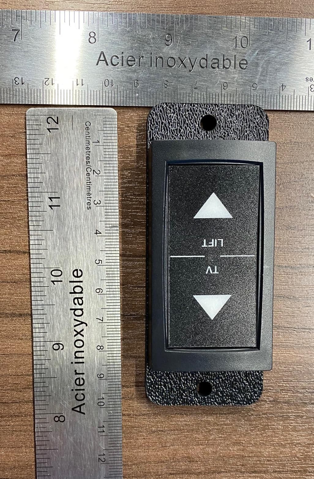
Jan 07, 2021Two Position switch for periodic TX applications
Equipment Class
DSC - Part 15 Security/Remote Control Transmitter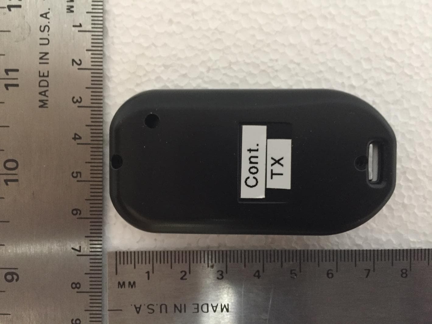
OV9BSSPWZIPA
Dec 17, 2020RF Fob for periodic TX applications
Equipment Class
DSC - Part 15 Security/Remote Control Transmitter