OVNAC7OEM card reader use to control access with NFC
STid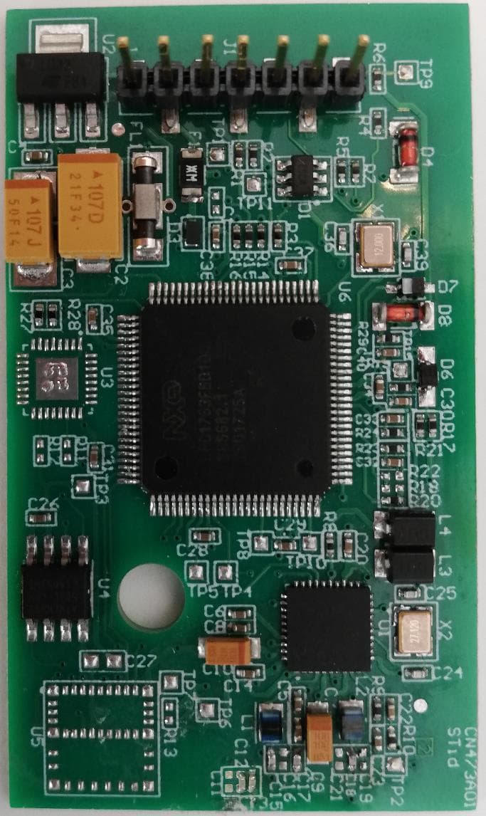
Click to zoom
Application Details
- Equipment Class
- DXX - Part 15 Low Power Communication Device Transmitter
- Date of Grant
- May 14, 2020
- Application Purpose
- Original Equipment
- Date of Application
- May 14, 2020
- Equipment Note
- OEM card reader use to control access with NFC
- Frequency Range
- 13.56000000 - 13.56000000
- Company
- STid
- Country
- France
Documents & Files
Document Text
Text extracted from the exhibit documents filed with the FCC. Open a document above to read the original.
Users Manual
OEM Module MS2 13.56 MHz MS2S 13.56 MHz & Blue Installation instructions Module OEM MS2 13,56 MHz MS2S 13,56 MHz & Blue Notice d’installation Módulo OEM MS2 13.56 MHz MS2S 13.56 MHz & Blue Procedimiento de instalación conforme con NOM-024 -SCFI-2013 © STid - 20 PA des Pradeaux FR13850 Gréasque – NI1140A02- Page 1 sur 6 - Ed. 04/05/2020 STid reserves the right to make change without notice, for the purpose of product improvement. Products / Connection Power supply characteristics Use an AC/DC power supply type LPS, Limited Power Source (as per IEC EN UL 60950-1 Ed2) or type ES1, PS1 (according to IEC EN UL 62368-1) for the main supply. Main power supply: Range: +4.5 Vdc to +9 Vdc Typical: 5 Vdc Max. consumption at 5 Vdc: MS2: 180mA MS2S: 190mA Regulated output: 3.3 Vdc Characteristics Communication: Asynchronous RS232 serial link with TTL levels / TTL (Wiegand / Clock and Data). Connector output: HE14 male 7 pins. Pull-up resistors: For Data signals, pull-up resistors are connected internally to 3.3 Volts. Protection: Tropicalized electronic board. Precautions for installation ▪ The supply voltage at the reader’s connector should be between +4.5 Vdc and +9 Vdc. ▪ We recommend using a filtered and regulated power supply. ▪ As far as possible, keep the reader away from computer or power source cables. They can generate electrical interference, depending on their radiation level and the proximity of the reader. ▪ Maximum distance between reader and the controller board: 500 mm. ▪ Recommended distance between two readers: parallel plane: 11.8 in – same plane: 15.8 in – perpendicular plane: 11.8 in. ▪ Recommended distance between two Blue readers: 78.74 inch either plan. ▪ Readers installed on a metal surface causes a very strong reduction in reading distance. ▪ Connect the wires or the connector of the reader BEFORE powering on. ▪ The signals are of the RS232-TTL form, do not connect the reader directly to a RS232 serial port. ▪ Operating temperature: -22°F to 158°F / -30°C to +70°C Read only readers (R31 & S31) Read / Write readers (W31) LED The operating mode can be programmed by a configuration card. The operating mode can be controlled by the SSCP commands. Switch input The initial status of the input “Switch” is memorized when the power supply is turned on. If the status becomes different from the initial status, the reader is wrenched ▪ and the wrenching signal will be emitted on the “Data/ D1” line. ▪ This function is configurable via a configuration card (SCB). The initial status of the input “Switch” is memorized when the power supply is turned on. If the status becomes different from the initial status, the reader is wrenched and the reader will perform the operations configured with the SSCP protocol. Reader configuration Readers are configurable with the SCB configuration card or virtual configuration card created with SECard. ▪ - If the SCB is compatible with the firmware: the LED lights green for 1 s. ▪ - If the SCB is not compatible with the firmware: the LED lights red for 1 s. ▪ - If the SCB key is different from the reader ‘s key: no reaction. ▪ Caution: set your reader with your own company key. Blue-NFC settings can be configured by SCB RW configuration badge created with SECard v3.3 minimum or by the SSCP commands. Caution: set your reader with your own company key. Powering-up the readers 1. Initialization: activation of the white LED for 10 s. 2. Indication of the reader type: activation of the LED according to the color code: Cyan = +5, Magenta = +1. 3. Indication of the firmware version: activation of the LED according to the color code: Red = +10, Orange = +5, Green = +1. 4. Waiting firmware update: the orange LED flashes for 5 s. 5. Activation of the default LED (fixed blue if no customer specific configuration). 1. Activation of the white LED for 1 s. MS2S-A Type Pin Wiegand Clock & Data RS232-TTL 7 Not Connected 6 Switch 5 Clock Clock Rx 4 D1 Data Tx 3 D0 Code NC 2 +Vcc (+4.5 Vdc to +9 Vdc) 1 0 Vdc MS2-A US FR ES 7 6 5 4 3 2 1 7 6 5 4 3 2 1 OEM Module MS2 13.56 MHz MS2S 13.56 MHz & Blue Installation instructions Module OEM MS2 13,56 MHz MS2S 13,56 MHz & Blue Notice d’installation Módulo OEM MS2 13.56 MHz MS2S 13.56 MHz & Blue Procedimiento de instalación conforme con NOM-024 -SCFI-2013 © STid - 20 PA des Pradeaux FR13850 Gréasque – NI1140A02- Page 2 sur 6 - Ed. 04/05/2020 STid reserves the right to make change without notice, for the purpose of product improvement. RS232-TTL communication Dimensions (in inch) General tolerance following ISO NFT 58-000 standard. FCC integration requirement 1- The module is limited to OEM installation ONLY. 2- The OEM integrator is responsible for ensuring the end user has no manual instructions to remove or install module. 3- The module is limited to installation in mobile or fixed application. 4- The separate approval is required for all other operating configurations, including portable configuration with respect to Part 2.1093 and different antenna configurations. 5- Labeling instructions of finished (host) product. Note that this label must include both this module’s ID and the included module’s ID. Declaration of compliance STid declares that the MS2-A/MS2S-A reader is compliant to the essential requirements of the Directives RED 2014/53/EU and RoHs 2011/65/EU. A copy of our declaration is available on request from [email protected]. MS2/MS2S reader complies with Part 15 of the FCC rules. Operation is subject to the following two conditions: 1) This device may not cause harmful interference. 2) This device must accept any interference received, including interference that may cause undesired operation. Note: The manufacturer is not responsible for any radio or TV interference caused by unauthorized modifications to this equipment. Such modifications could void the user’s authority to operate the equipment. This device complies with the safety requirements for RF exposure in accordance with §1.1307(b), 2.1091 and 2.1093 of the F…
Text truncated - open the document above for the full version.
Cover Letter(s)
Agence Paris – IdF : Immeuble Le Trysalis 416 avenue de la Division Leclerc – 92290 Chatenay-Malabry, France Tél. : +33 (0)1.43.50.11.43 - Fax : +33 (0)1.43.50.27.37 Siège Social : 20 Parc d’Activités des Pradeaux, 13850 GREASQUE - France Tél. : +33 (0)4.42.12.60.60 - Fax : +33 (0)4.42.12.60.61 Email : [email protected] - Web : http://www.stid.com S.A.S. au capital de 1 000 000 € - RCS Marseille 408 472 751 Siret 408 472 751 00044 – NAF 7112B - N° TVA 96 408 472 751 Federal Communications Commission Authorization and Evaluation Division The 24 TH of March 2020 in Gréasque Subject: Confidentiality Request regarding application for certification of FCC ID: OVNAC7 Applicant: STid Product: MS2-A Model: ARC-AC7 To Whom It May Concern: Pursuant to Sections 0.457 and 0.459 of the Commission’s Rules, we hereby request confidential treatment of information accompanying this application as outlined below: Exhibit Type File Name Block Diagram Schematics Operational Description Parts List (ARC-AC7) BlkDia.pdf” (ARC-AC7) Schematics.pdf” (ARC-AC7) OpDes.pdf” (ARC-AC7) PartsList.pdf The above materials contain trade secrets and proprietary information not customarily released to the public. The public disclosure of these materials may be harmful to the applicant and provide unjustified benefits to its competitors. The applicant understands that pursuant to Section 0.457 of the Rules, disclosure of this application and all accompanying documentation will not be made before the date of the Grant for this application. If you have any queries, please do not hesitate to contact us. Regards, Sylvain Poitrat Technical Director
Cover Letter(s)
Agence Paris – IdF : Immeuble Le Trysalis 416 avenue de la Division Leclerc – 92290 Chatenay-Malabry, France Tél. : +33 (0)1.43.50.11.43 - Fax : +33 (0)1.43.50.27.37 Siège Social : 20 PA des Pradeaux, 13850 GREASQUE - France Tél. : +33 (0)4.42.12.60.60 - Fax : +33 (0)4.42.12.60.61 Email : [email protected] - Web : http://www.stid.com S.A.S. au capital de 1 000 000 € - RCS Marseille 408 472 751 Siret 408 472 751 00044 – NAF 7112B - N° TVA 96 408 472 751 May 4, 2020 in Gréasque Subject: RADIO Certification of MS2 Applicant: Sylvain Poitrat FCC ID : OVNAC7 IC : 10520A-MS2 PMN : MS2-A HVIN : ARC-AC7 To Whom It May Concern: We would like to submit the above product for Certification concerning FCC/IC rules using the Limited Modular Approval (LMA) procedure. Please review all required documents enclosed. This application is a card reader use to control access with NFC. It is an OEM module and it must be installed by the customers in his application. Compliance for RF exposure requirement was demonstrated in this test report. If you have any queries, please do not hesitate to contact us. Regards, Sylvain Poitrat Technical Director
Cover Letter(s)
STid 20 PA des Pradeaux 13850 GREASQUE Subject.: Acknowledgment of FCC Modular approval requirements March 24, 2020 FCC ID: OVNAC7 To Whom It May Concern: The MS2 module is a card reader use to control access with NFC. It is an OEM module and it must be installed by the customers in their application. Modular Approval Requirement Yes No (i) The radio elements of the modular transmitter must have their own shielding. The physical crystal and tuning capacitors may be located external to the shielded radio elements. X (*) (ii) The modular transmitter must have buffered modulation/data inputs (if such inputs are provided) to ensure that the module will comply with part 15 requirements under conditions of excessive data rates or over- modulation. X (iii) The modular transmitter must have its own power supply regulation. X (iv) The modular transmitter must comply with the antenna and transmission system requirements of §§ 15.203, 15.204(b) and 15.204(c). The antenna must either be permanently attached or employ a ‘‘unique’’ antenna coupler (at all connections between the module and the antenna, including the cable). The ‘‘professional installation’’ provision of § 15.203 is not applicable to modules but can apply to limited modular approvals under paragraph (b) of this section. X (**) (v) The modular transmitter must be tested in a stand-alone configuration X (vi) The modular transmitter must be equipped with either a permanently affixed label or must be capable of electronically displaying its FCC identification number. X (vii) The modular transmitter must comply with any specific rules or operating requirements that ordinarily apply to a complete transmitter and the manufacturer must provide adequate instructions along with the module to explain any such requirements. A copy of these instructions must be included in the application for equipment authorization. X (viii) The modular transmitter must comply with any applicable RF exposure requirements in its final configuration. X (***) X (*) integrator shall measure the radiation of the product and check that it meets the current standards. X (**) antenna is integrated on the product. X (***) integrator shall perform tests to make sure that the product complies with any applicable RF exposure requirements. Sylvain Poitrat Technical Director
Cover Letter(s)
Attn: TIMCO Engineering Inc. 849 N.W. State Road 45 P.O. Box 370 Newberry, Florida 32669 Authority to Act as Agent On our behalf, I appoint M. Olivier HEYER from Emitech Montpellier – 145 rue du Massacan – 34741 VENDARGUES CEDEX FRANCE, to act as our agent in the preparation of this application for equipment certification. I certify that submitted documents properly describe the device or system for which equipment certification is sought. I also certify that each unit manufactured, imported or marketed, as defined in the Federal Communications Commission’s regulations will have affixed to it a label identical to that submitted for approval with this application. For instances where our authorized agent signs the application for certification on our behalf, I acknowledge that all responsibility for complying with the terms and conditions for certification, as specified by FCC, still resides with STID, 20 Parc d’activités des Pradeaux -13850 GREASQUE, France This authorization is valid until further written notice from STID. The 20th of November 2019 By Sylvain Poitrat Technical Director
External Photos
ExtPho 29/04/2020 1/1 Author : Benoît BERLAND Motherboard front back 35mm 60mm HF part side 12mm 5.02m m
ID Label/Location Info
LabelLoc 24/03/2019 1/1 Author : Benoît BERLAND FCC information is located on the back of the product
ID Label/Location Info
ET053I04.xlsx LD ET 24/03/2020 Rédigé par H.VANDEVOORDE 24/03/2020 Référence I04 ETIQUETTE SECURITE ELEC GAMME MS2 (PF) Approuvé par Nom Date Visa 24/03/2020 B.BERLAND 053 Vérifié par J.SILVE Produit Désigné Réf.Ed.Var. Exemple : ARC-AC7 5V-180mA 5mm Symboles : CEI 60417 / N°5031 Directive RED 2014/53/UE Directive Rohs 2011/65/UE 12,7mm 25,4mm IC : 10520A-MS2 FCC ID:OVNAC7 L'étiquette fait partie de la liste des composants critiques UL et doit respecter la description technique suivante : Adhesive, suitable for plastic material and rated 80°C. With ribbon R7960 and BBP12 or BBP11 printers Ex : Brady B-423-B ou équivalent MS2-A 24/03/2020Ce document est la propriété de STId, et ne peut être reproduit ni communiqué sans autorisation préalable écrite.Page 1/1
Internal Photos
ExtPho 29/04/2020 1/1 Author : Benoît BERLAND Motherboard front back 35mm 60mm HF part side 12mm 5.02m m
Test Report
Siège Social : Emitech - 3, avenue des Coudriers - Z.A. de l’Observatoire - 78180 MONTIGNY LE BX - France Siret : 344 545 645 00022 - Tél. : 33 (0)1 30 57 55 55 - Fax : 33 (0)1 30 43 74 48 - E-mail : [email protected] - URL : www.emitech.fr SAS au capital de 1 560 000 € - R.C.S. VERSAILLES 344 545 645 - APE 7112B RR410-20-100109-1A Ed.0 Duplication of this test report is only permitted for an integral photographic facsimile. It includes the number of pages referenced here above. This document is the result of testing a specimen or a sample of the product submitted. It does not imply an assessment of the conformity of the whole manufactured products of the tested sample. LISTE DES SITES ACCREDITES ET PORTEES DISPONIBLES SUR WWW.COFRAC.FR ACCREDITATIONS N° 1-0107, 1-0826, 1-0827, 1-1925, 1-2069,1-2070, 1-2206, 1-2376 & 1-6086 Test report issued under the responsibility of: EMITECH MONTPELLIER laboratory MRA US-EU Designation Number: FR0006 (FCC#: 954701) Canadian CAB Identifier: FR0003 (ISED#: 4379C) RADIO TEST REPORT FCC Part 15 FCC Part 15.225 RSS-210_Issue 10: 2019 RSS/CNR-Gen, Issue 5: 2019 Company ......................................... : STid Address............................................. : 20 PA des Pradeaux - Boulevard S. Allende 13850 GREASQUE - FRANCE Test item description. .................... : RFID Reader Module Trade Mark. ...................................... : STid FCC ID. ............................................. : OVNAC7 IC. ..................................................... : 10520A-MS2 Manufacturer. ................................... : STid Model/Type reference. ...................... : ARC-AC7 / MS2-A Ratings.............................................. : 4.5Vdc to 9 Vdc Testing Laboratory ......................... : EMITECH MONTPELLIER laboratory Address............................................. : 145 rue de Massacan 34740 VENDARGUES FRANCE Report Reference No. ..................... : RR410-20-100109-1A Test procedure. ................................ : FCC IC Certification Diffusion. ........................................... : Mr BERLAND Applicant’s name. ............................. : STid Date of issue. .................................... : May 13, 2020 Total number of pages. ..................... : 36 Revision. ........................................... : 0 Modified page(s). .............................. : Creation Compiled by. ..................................... : Olivier AELBRECHT Approved by (+ signature). ............... : David MONTAULON (Technical Manager) RR410-20-100109-1A Ed.0 Page 2 on 36 REPORT INDEX: 1. GENERAL INFORMATIONS .......................................................................................................................... 3 2. REFERENCE DOCUMENT(S) ........................................................................................................................ 4 3. EQUIPMENT TECHNICAL DESCRIPTION .................................................................................................... 5 3.1. TEST CONDITIONS ................................................................................................................................... 5 3.2. EUT MARKING PLATE .............................................................................................................................. 5 3.3. EUT GENERAL VIEW ................................................................................................................................ 6 3.4. EUT MECHANICAL AND ELECTRICAL DESIGN ............................................................................................. 6 3.5. EUT INPUT/OUTPUT PORTS ...................................................................................................................... 7 3.6. SUPPORTING EQUIPMENT USED DURING TEST .......................................................................................... 7 3.7. EUT RADIO SPECIFICATIONS .................................................................................................................... 8 4. RESULT SUMMARY ....................................................................................................................................... 9 5. MEASUREMENT UNCERTAINTY ................................................................................................................ 10 6. TEST CONDITIONS AND RESULTS ........................................................................................................... 11 6.1. CONDUCTED VOLTAGE EMISSION (MEASUREMENT)................................................................................... 11 6.2. OCCUPIED BANDWIDTH, 20 DB BANDWIDTH & 6DB BANDWIDTH ............................................................... 14 6.3. RADIATED SPURIOUS EMISSIONS ............................................................................................................. 19 6.4. FIELD STRENGTH IN THE BAND 13.553-13.567MHZ ................................................................................. 29 6.5. FIELD STRENGTH OUTSIDE THE BAND 13.110-14.010MHZ ....................................................................... 33 6.6. MEASUREMENT OF FREQUENCY STABILITY .............................................................................................. 35 REVISION HISTORY: Revision Date Modified pages Modifications 0 May 13, 2020 / Creation RR410-20-100109-1A Ed.0 Page 3 on 36 1. GENERAL INFORMATIONS This document submits the results of Radio tests performed on the equipment RFID Reader Module MS2- A (denominated hereafter E.U.T.: equipment under test) according to document(s) listed in §2 of this test report. TESTING PROCEDURE AND TESTING LOCATION: Testing Location ......................................... : EMITECH MONTPELLIER laboratory & Open Area Test Site in SALINELLES (30) Address......................................................... : 145 rue de Massacan 34740 VENDARGUES FRANCE Test procedure. ...............…
Text truncated - open the document above for the full version.
Test Setup Photos
RR410-20-100109-1A Ed.0 Page 12 on 36 TEST SETUP PHOTO(S) CONDUCTED EMISSION (MEASUREMENT) - TABULATED RESULTS AC POWER SOURCE / RF ON 50OHMS LOAD EMI4568 Terminal Test Frequency (MHz) Meter Reading dB (μV) Detector (Pk/QP/Av) Gain/Loss Factor (dB) Level dB (μV) Avg Limit dB (μV) Margin (dB) Neutral 2.558 22.88 Pk 10.45 33.33 46 -12.67 Neutral 6.443 21.06 Pk 10.49 31.55 50 -18.45 Neutral 15.951 20.9 Pk 10.44 31.34 50 -18.66 Neutral 29.492 33.01 Pk 10.43 43.44 50 -6.56 Phase 1.853 23.63 Pk 10.43 34.06 46 -11.94 Phase 3.090 23.21 Pk 10.46 33.67 46 -12.33 Phase 15.655 21.03 Pk 10.45 31.48 50 -18.52 Phase 29.492 29.54 Pk 10.43 39.97 50 -10.03 Supplementary information: N/A RR410-20-100109-1A Ed.0 Page 23 on 36 TEST SETUP PHOTO(S) - FOR FREQ < 30MHZ (FINAL MEASUREMENT) TEST SETUP PHOTO(S) - FOR 30MHZ < FREQ < 200MHZ RR410-20-100109-1A Ed.0 Page 24 on 36 TEST SETUP PHOTO(S) - FOR 200MHZ < FREQ < 1GHZ RR410-20-100109-1A Ed.0 Page 21 on 36 TEST SETUP PHOTO(S) – EUT POSITIONS RR410-20-100109-1A Ed.0 Page 22 on 36 TEST SETUP PHOTO(S) – EUT POSITIONS TEST SETUP PHOTO(S) - FOR FREQ < 30MHZ (PRE MEASUREMENT) RR410-20-100109-1A Ed.0 Page 32 on 36 TEST SETUP PHOTO(S) RR410-20-100109-1A Ed.0 Page 30 on 36 FIELD STRENGTH IN THE BAND 13.553-13.567MHZ - TABULATED RESULTS TEST CONDITION ANTENNA POS. AZIM. FREQUENCY LEVEL AT 10m (dBμA/m) LIMIT AT 10m (dBμA/m) RESULT TAB. Position 1 0° 13.56 MHz 0.944 51.58 EMI4472 Position 1 45° 13.56 MHz -3.556 51.58 EMI4521 Position 1 90° 13.56 MHz -14.756 51.58 EMI4522 Position 2 0° 13.56 MHz -16.056 51.58 EMI4523 Position 2 45° 13.56 MHz -18.156 51.58 EMI4524 Position 2 90° 13.56 MHz -15.756 51.58 EMI4525 Position 3 0° 13.56 MHz -0.456 51.58 EMI4526 Position 3 45° 13.56 MHz -4.756 51.58 EMI4527 Position 3 90° 13.56 MHz -13.856 51.58 EMI4528 Maximun level at 10m is 0.94dBμA/m for a limit at 51.58 dBμA/m. Using an extrapolation factor of 40dB/dec and a conversion factor of -51.5dB, level at 30m is 33.36 dBμV/m for a limit at 84 dBμV/m. EUT MODIFICATIONS OPERATOR TEST DATE RESULT TAB. N/A OAT 19/03/2020 - TEST SETUP PHOTO(S) – EUT POSITION 1 RR410-20-100109-1A Ed.0 Page 31 on 36 TEST SETUP PHOTO(S) – EUT POSITION 2 TEST SETUP PHOTO(S) – EUT POSITION 3
Contact Information
Applicant
POITRAT Sylvain(Technical Director)
Test Firm
EMITECH MontpellierOlivier HEYER
Technical Specifications
| # | Rule Parts | Frequency Range | Power Output |
|---|---|---|---|
| 1 | 15C | 13.56 MHz - 13.56 MHz | - |
Other Applications from STid
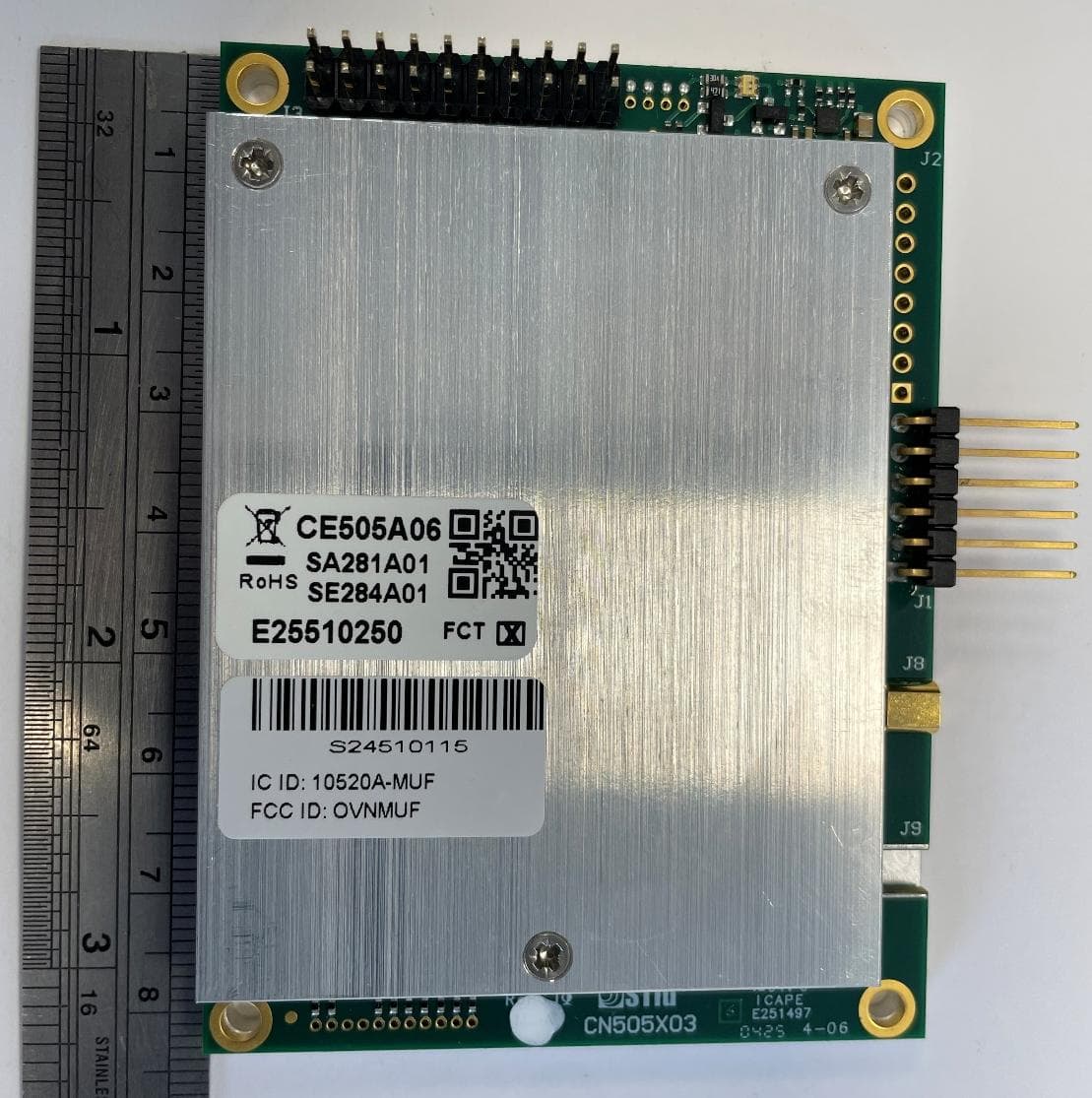
OVNMUF
May 07, 2026RFID radio module
Equipment Class
DSS - Part 15 Spread Spectrum Transmitter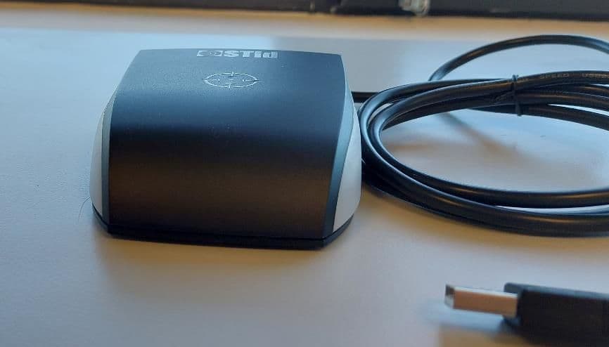
OVNAC9
Mar 26, 2023RFID communication between reader (i.e., ARC W55) and passive tag by using an UHF Carrier (902MHz to 928MHz)
Equipment Class
DSS - Part 15 Spread Spectrum Transmitter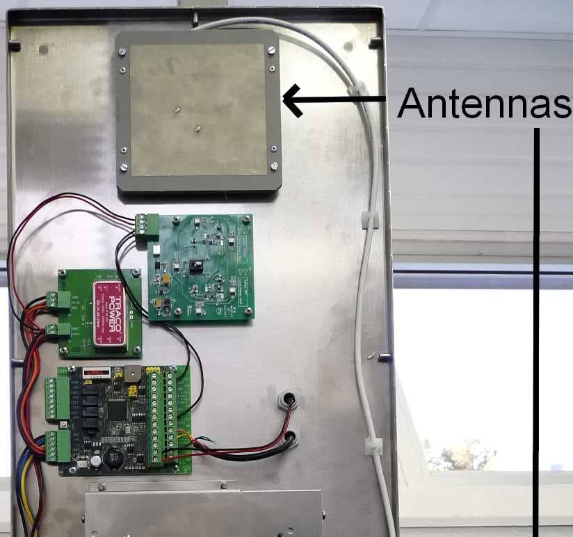
OVNURF
Feb 14, 2013TAG READER
Equipment Class
DSS - Part 15 Spread Spectrum Transmitter