OVNURFTAG READER
STid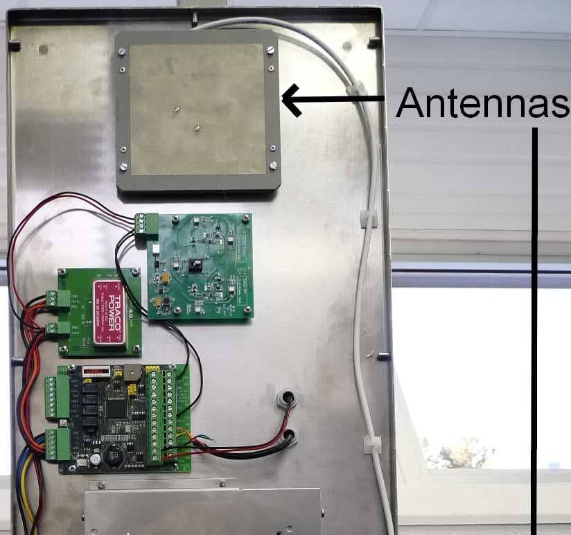
Click to zoom
Application Details
- Equipment Class
- DSS - Part 15 Spread Spectrum Transmitter
- Date of Grant
- Feb 14, 2013
- Application Purpose
- Original Equipment
- Date of Application
- Feb 14, 2013
- Equipment Note
- TAG READER
- Frequency Range
- 902.75000000 - 927.25000000
- Company
- STid
- Country
- France
Documents & Files
Document Text
Text extracted from the exhibit documents filed with the FCC. Open a document above to read the original.
Users Manual
Notice d’installation / Installation procedure Lecteur UHF / UHF Reader: GAT © STid 2012 – NI1081B02 - Ed. 16/01/2013 Références des produits Versions monobloc GAT -R41-E-U04-xx/2 (ETSI) Modèle TTL (Clock&Data / Wiegand) GAT -R42-E-U04-xx/2 (ETSI) Modèle RS232 GAT -R43-E-U04-xx/2 (ETSI) Modèle RS485 GAT -R51-E-U04-xx/2 (FCC) Modèle TTL (Clock&Data / Wiegand) GAT -R52-E-U04-xx/2 (FCC) Modèle RS232 GAT -R53-E-U04-xx/2 (FCC) Modèle RS485 Versions portique GAT -R41-F-U04-xx/2 (ETSI) Modèle TTL (Clock&Data / Wiegand) GAT -R42-F-U04-xx/2 (ETSI) Modèle RS232 GAT -R43-F-U04-xx/2 (ETSI) Modèle RS485 GAT -R51-F-U04-xx/2 (FCC) Modèle TTL (Clock&Data / Wiegand) GAT -R52-F-U04-xx/2 (FCC) Modèle RS232 GAT -R53-F-U04-xx/2 (FCC) Modèle RS485 Caractéristiques Alimentation : +9 Vdc à +36 Vdc (+12 Vdc Typique) Consommation : 2.5 A sous +12 Vdc Communication: RS485 (L+ & L-) RS232 (TD & RD) TTL (Wiegand / Clock & Data) Raccordement : Bornier à vis 2 points & Bornier à vis 8 points Pas de 5,08 mm Température de fonctionnement : -20 °C / +55°C -4,00 °F / +131,00°F Indice de protection : IP66 / Ik07 Puce lue : EPC1 Gen2 (ISO 18000-6C) 96 bits max. Relais: 1 A max sous 30 Vdc. Type de câble préconisé Utiliser du câble multiconducteur blindé par tresse, reliée à la masse du concentrateur. Déport max RS485 : 1000 m. à 9600 bauds (SYT2 6/10 ° conseillé) Déport max RS232 : 15 m. (SYT2 6/10 ° conseillé) Wiegand / Clock & Data: Communication Pour plus d’informations concernant le dialogue avec le lecteur, veuillez consulter la spécification du protocole. Vue générale Les différents composants et les connexions du lecteur sont ci-dessous. Pour plus d’informations, se reporter au chapitre Détails. Products references One antenna variants GAT -R41-E-U04-xx/2 (ETSI) TTL Model (Clock&Data / Wiegand) GAT -R42-E-U04-xx/2 (ETSI) RS232 Model GAT -R43-E-U04-xx/2 (ETSI) RS485 Model GAT -R51-E-U04-xx/2 (FCC) TTL Model (Clock&Data / Wiegand) GAT -R52-E-U04-xx/2 (FCC) RS232 Model GAT -R53-E-U04-xx/2 (FCC) RS485 Model Gate variants GAT -R41-F-U04-xx/2 (ETSI) TTL Model (Clock&Data / Wiegand) GAT -R42-F-U04-xx/2 (ETSI) RS232 Model GAT -R43-F-U04-xx/2 (ETSI) RS485 Model GAT -R51-F-U04-xx/2 (FCC) TTL Model (Clock&Data / Wiegand) GAT -R52-F-U04-xx/2 (FCC) RS232 Model GAT -R53-F-U04-xx/2 (FCC) RS485 Model Characteristics Power supply: +9 Vdc up to +36 Vdc (+12 Vdc Typical) Consumption: 2.5 A Under +12 Vdc Communication: RS485 (L+ & L-) RS232 (TD & RD) TTL (Wiegand / Clock & Data) Pin out: Connector 2 points & Connector 8 points Thread 5.08 mm / 0.2000 in Temperature: -20 °C / +55°C -4.00 °F / +131.00°F Protection: IP66 / Ik07 Chip: EPC1 Gen2 (ISO 18000-6C) 96 bits max. Relay: 1 A max under 30 Vdc. Recommended cables Use a multi-conductor cable, pair shielded. Max length RS485: 1000 m / 3 280.84 ft at 9600 bps (SYT2 AWG24 Recommended) Max length RS232: 15 m / 49.21 ft. (SYT2 AWG24 recommended) Wiegand / Clock & Data: Communication More details about reader’s communication are available in the protocol specification Overview The different components and the connexions are represented below. For more details, please refer to the Details chapter. 0 Alimentation 1 GND 2 GND 3 GND 4 IN1 5 L+/TD/Data/D0 Voie 1 6 L-/RD/Clock/D1 Voie 1 7 NC 8 NC 9 NC 10 NC 11 NC 12 NC 13 NC 14 NC 15 NC 16 NC 17 NC 18 NC 19 NC 20 NC 21 NC 22 NC 23 NC 24 NC 25 NC 26 NC 27 NC 28 NC 29 NC 30 NC 31 NC 32 NC 33 NC A Vis de fixation TORX M3x12 B Coupleur UHF C Carte alimentation D Carte Interface E Antenne F LED de visualisation G Information visuelle communication Coupleur UHF H Information visuelle communication Host I Buzzer J Bornier de connexion K Presse-étoupes L Résistance de fin de lignes M Switch SW1 N Commutateur de filtrage O Voie IN 1-4 P Relais 1-4 A Screws TORX M3x12 B UHF Coupler C Power supply board D Interface board E Antenna F Led of visualization G Indication for communication with the UHF coupler H Indication for communication with the Host I Buzzer J Connector K Stuffing box L End of line resistor M Switch SW1 N Filtering Switch O Lane IN 1-4 P Relay 1-4 1 paire 6/10° - 30 m max 1 paire 9/10° - 50 m max 2 paires 6/10° - 60 m max 2 paires 9/10° - 100 m max 3 paires 6/10° - 100 m max 1 pair AWG24 - 98,43 ft / 30 m max 1 pair AWG35 - 164,04 ft / 50 m max 2 pairs AWG24 - 196,85 ft / 60 m max 2 pairs AWG35 - 328,08 ft / 100 m max 3 pairs AWG24 -328,08 ft / 100 m max 0 Power Supply 1 GND 2 GND 3 GND 4 IN1 5 L+/TD/Data/D0 Voie 1 6 L-/RD/Clock/D1 Voie 1 7 NC 8 NC 9 NC 10 NC 11 NC 12 NC 13 NC 14 NC 15 NC 16 NC 17 NC 18 NC 19 NC 20 NC 21 NC 22 NC 23 NC 24 NC 25 NC 26 NC 27 NC 28 NC 29 NC 30 NC 31 NC 32 NC 33 NC Notice d’installation / Installation procedure Lecteur UHF / UHF Reader: GAT © STid 2012 – NI1081B02 - Ed. 16/01/2013 Fonctionnement Initialisation du lecteur de 12 secondes à la mise sous tension. Tous les paramètres sont pris à ce moment (voir §Configuration de la carte interface) La led verte de visualisation reste allumée. A la fin de l’initialisation, le lecteur recherchera un tag de configuration sur l’antenne pendant 4 secondes. Clignotement de la led de visualisation pendant 4 secondes. Si un badge de configuration est présenté sur l’antenne principale, la led clignote rapidement 6 fois signalant ainsi la prise en compte du badge. Le lecteur peut gérer une anticollision à hauteur de 4 tags. Si plusieurs tags sont présents dans le même champ, un délai d’environ 200 ms sépare l’envoi de chaque identifiant. Pour une Le cycle de scan, variant suivant le nombre de tags présents, est au plus rapide de 100 ms. Un tag lu provoque un clignotement de la led verte de visualisation, un bip sonore du buzzer ainsi que l’activation du Relais 1 pendant 200 ms. Chaque antenne principale (maître et esclave), est composée de deux antennes (repérées E) situées sous le capot (soit un total de 2 pour la version monobloc ou 4 pour la version portique). Ces antennes E fonctionnent en multiplexage et…
Text truncated - open the document above for the full version.
Cover Letter(s)
Agence Paris – IdF : Expansion 10 000 Siège Social : 20 parc d’activité des Pradeaux, 28 rue de la redoute – 92260 Fontenay Aux Roses, France Bld Salvador Allende ‐ 13850 GREASQUE ‐ France Tél. : +33 (0)1.43.50.11.43 ‐ Fax : +33 (0)1.43.50.27.37 Tél. : +33 (0)4.42.12.60.60 ‐ Fax : +33 (0)4.42.12.60.61 E‐M@il : [email protected] ‐ Web : http://www.stid.com S.A. au capital de 152 449 € ‐ RCS Marseille B 408 472 751 Siret 408 472 751 00044 ‐ APE 742C ‐ N° TVA 96 408 472 751 1/2 Federal Communications Commission Authorization and Evaluation Division Gréasque (France), 20th january 2013 Subject: Acknowledgment of Modular approval requirements Applicant: STid Product: URF Model: W52 FCC ID: OVNURF IC ID: 10520A‐URF To whom it may concern, The UHF RFID Module W52 manufactured by STID is only provided to be included in GAT‐R5X‐X range of products (hosts). The GAT hands‐free reader can identify a moving person in a 2 or 4 m wide corridor by reading a UHF tag. Single or dual‐antenna configurations are possible, depending on the area to be covered. GAT System can be installed indoors or outdoors. Two versions are available to ensure the highest level of performance, whatever the configuration of buildings: a single‐unit version (2 built‐in antennas) or a gate version (2 x 2 antennas). For each configuration, there is only one RF module. It is named URF The system can use several standard communication interfaces (TTL, RS232 and RS485). GAT‐R5X‐X system is identified in several models: • GAT‐R52‐E: RS232 model, single‐unit. • GAT‐R51‐E: TTL Model (Clock&Data / Wiegand) model, single‐unit. • GAT‐R53‐E: RS485 model, single‐unit. • GAT‐R52‐F: RS232 model, gate version. • GAT‐R51‐F: TTL Model (Clock&Data / Wiegand) model, gate version. • GAT‐R53‐F: RS485 model, gate version. The gate version includes a single unit with another unit (linked by an RF cable connected to URF module) which includes only two deported antennas. Agence Paris – IdF : Expansion 10 000 Siège Social : 20 parc d’activité des Pradeaux, 28 rue de la redoute – 92260 Fontenay Aux Roses, France Bld Salvador Allende ‐ 13850 GREASQUE ‐ France Tél. : +33 (0)1.43.50.11.43 ‐ Fax : +33 (0)1.43.50.27.37 Tél. : +33 (0)4.42.12.60.60 ‐ Fax : +33 (0)4.42.12.60.61 E‐M@il : [email protected] ‐ Web : http://www.stid.com S.A. au capital de 152 449 € ‐ RCS Marseille B 408 472 751 Siret 408 472 751 00044 ‐ APE 742C ‐ N° TVA 96 408 472 751 2/2 Modular approval requirement Yes No i) The radio elements must have the radio frequency circuitry shielded. Physical components and tuning capacitor(s) may be located external to the shield, but must be on the module assembly; X ii) The module must have buffered modulation/data inputs to ensure that the device will comply with Part 15 requirements with any type of input signal; X iii) The module must contain power supply regulation on the module; X iv) The module must contain a permanently attached antenna, or contain a unique antenna connector, and be marketed and operated only with specific antenna(s), per Sections 15.203,15.204(b), 15.204(c), 15.212(a), 2.929(b); X v) The module must demonstrate compliance in a stand‐alone configuration; X vi) The module must be labelled with its permanently affixed FCC ID label, or use an electronic display (See KDB Publication 784748 about labelling requirements); X vii) The module must comply with all specific rules applicable to the transmitter. The grantee must provide comprehensive instructions to explain compliance requirements; X viii) The module must comply with RF exposure requirements. For any transmitters intended for use in portable devices, SAR compliance must be demonstrated to be independent of the host device. See KDB Publication 447498 as a guide to determine if a transmitter can be tested without being limited to a host device. If SAR compliance can only be demonstrated in specific host types or platforms, then the module type must be “limited.” X iv). Even if RF connectors of URF module are SMA connector, this radio module is included with antenna into a specific casing with power supply board and interface board. In addition, GAT reader are always sold to and installed by professional installers. v) URF module can only be used in one of the above GAT configurations for US and Canadian markets. If you have any queries, please do not hesitate to contact us. Regards, January 20th 2012 Sylvain POITRAT Technical Director STid
Cover Letter(s)
Agence Paris – IdF : Expansion 10 000 Siège Social : 20 parc d’activité des Pradeaux, 28 rue de la redoute – 92260 Fontenay Aux Roses, France Bld Salvador Allende ‐ 13850 GREASQUE ‐ France Tél. : +33 (0)1.43.50.11.43 ‐ Fax : +33 (0)1.43.50.27.37 Tél. : +33 (0)4.42.12.60.60 ‐ Fax : +33 (0)4.42.12.60.61 E‐M@il : [email protected] ‐ Web : http://www.stid.com S.A. au capital de 152 449 € ‐ RCS Marseille B 408 472 751 Siret 408 472 751 00044 ‐ APE 742C ‐ N° TVA 96 408 472 751 Federal Communications Commission Authorization and Evaluation Division Gréasque (France), 20th january 2013 Subject: Confidentiality Request regarding application for certification of FCC ID: OVNURF Applicant: STid Product: URF Model: W52 To Whom It May Concern: Pursuant to Sections 0.457 and 0.459 of the Commission’s Rules, we hereby request confidential treatment of information accompanying this application as outlined below: Exhibit Type Block Diagram Schematics Operational Description Parts List File Name W52 BlkDia.pdf” W52 Schem.pdf” W52 Opdes.pdf” W52 PartsLst.pdf The above materials contain trade secrets and proprietary information not customarily released to the public. The public disclosure of these materials may be harmful to the applicant and provide unjustified benefits to its competitors. The applicant understands that pursuant to Section 0.457 of the Rules, disclosure of this application and all accompanying documentation will not be made before the date of the Grant for this application. If you have any queries, please do not hesitate to contact us. Regards, January 20th 2012 Sylvain POITRAT Technical Director STid
Cover Letter(s)
Agence Paris – IdF : Expansion 10 000 Siège Social : 20 parc d’activité des Pradeaux, 28 rue de la redoute – 92260 Fontenay Aux Roses, France Bld Salvador Allende ‐ 13850 GREASQUE ‐ France Tél. : +33 (0)1.43.50.11.43 ‐ Fax : +33 (0)1.43.50.27.37 Tél. : +33 (0)4.42.12.60.60 ‐ Fax : +33 (0)4.42.12.60.61 E‐M@il : [email protected] ‐ Web : http://www.stid.com S.A. au capital de 152 449 € ‐ RCS Marseille B 408 472 751 Siret 408 472 751 00044 ‐ APE 742C ‐ N° TVA 96 408 472 751 Federal Communications Commission Authorization and Evaluation Division Gréasque (France), 20th january 2013 Subject: Product sold and installation Applicant: STid Product: URF Model: W52 FCC ID: OVNURF IC ID: 10520A‐URF To whom it may concern, I, undersigned, Sylvain POITRAT, Technical Director, declares that products range READERS GAT‐R5X‐X that contains UHF module W52 is: ‐ exclusively sold to professional installers and dealers that have the necessary knowledge configure and install the device in accordance to the FCC part 15 Radio part 15.247. ‐ exclusively installed by professional installer and dealers that have the necessary knowledge configure and install the device in accordance to the FCC part 15 Radio part 15.247. and declares that the intended use of this device is for industrial or commercial use. If you have any queries, please do not hesitate to contact us. Regards, January 20th 2012 Sylvain POITRAT Technical Director STid
External Photos
URFW52 ExtPHO.pdf Author: N.Sogoyan Date: July 2012 URFW52 ExtPHO.pdf Author: N.Sogoyan Date: July 2012
Internal Photos
Internal view RFID board without EMI Shield (RF blocks are colore d) RFID board With EMI Shield (RF blocks are colored) RFID board solder side (RF blocks are colored). No EMI shield is mounted
RF Exposure Info
R041-12-102605-2A - DM / CHB EVALUATION OF HUMAN EXPOSURE TO ELECTROMAGNETIC FIELDS According to the standard(s): EN 50364:2010 Equipment under test: UHF HANDSFREE COMPACT READER GAT-R5X-X Company: STID Diffusion: Mr POITRAT (Company: STID) Number of pages: 12 including 1 annex Ed. Date Modified page(s) Written by Name Visa Technical verification Quality approval Name Visa 0 12-Dec-12 Creation David MONTAULON Regis GONZALEZ Duplication of this report is only permitted for an integral photographic facsimile. It includes the number of pages referenced above. This document is the result of testing a specimen or a sample of the product submitted. It does not imply an assessment of the conformity of the whole production of the item tested. R041-12-102605-2A Ed.0 PAGE : 2 NAME OF THE EQUIPMENT UNDER TEST (E.U.T.) : UHF HANDSFREE COMPACT READER GAT-R5X-X Serial number : / P/N : FCC ID: OVNURF IC ID:10520A - URF Software version : / MANUFACTURER’S NAME : STID APPLICANT’S ADDRESS: Company : STID Address : 283 ZA LES PRADEAUX - Boulevard Salvador Allende 13850 GREASQUE FRANCE Person(s) present during the tests : / Responsible : Mr POITRAT DATE(S) OF TESTS : November, the 28 th of 2012 TESTS LOCATION(S) : Emitech Grand Sud Laboratory in VENDARGUES (34) - FRANCE TESTS SUPERVISOR(S) : None TESTS OPERATOR(S) : David MONTAULON R041-12-102605-2A Ed.0 PAGE : 3 CONTENTS 1. INTRODUCTION ................................................................................................................................ 4 2. REFERENCE DOCUMENT(S) ........................................................................................................... 4 3. EQUIPMENT UNDER TEST CONFIGURATION ............................................................................... 4 4. EQUIPMENT UNDER TEST CONFIGURATION ............................................................................... 4 5. EQUIPMENT UNDER TEST CONFIGURATION SCHEME ............................................................... 6 6. SUMMARY OF TEST RESULTS ....................................................................................................... 7 7. SPACIALLY AVERAGE MEASUREMENT ....................................................................................... 8 ANNEX: RESULTS BOARD(S) AND PHOTOGRAPH(S) ......................................................................... 9 R041-12-102605-2A Ed.0 PAGE : 4 1. INTRODUCTION This report presents the results of the measurements performed on UHF HANDSFREE COMPACT READER GAT-R5X-X in order to verify the compliance of this product with the European standard EN 50364:2001 which requirements are derived from the European recommendation 99/519/EC 2. REFERENCE DOCUMENT(S) EN 50364:2001 Limitation of human exposure to electromagnetic fields from devices operating in the frequency range 0Hz to 10GHz, used in Electronic Article Surveillance (EAS), Radio Frequency Identification (RFID) and similar applications. EN 50357:2001 Evaluation of human exposure to electromagnetic fields from devices used in Electronic Article Surveillance (EAS), Radio Frequency Identification (RFID) and similar applications. Recommendation Limitation of exposure of the general public to electromagnetic fields. 99/519/EC of 12 July 1999 3. EQUIPMENT UNDER TEST CONFIGURATION Cycle and operating mode during emission tests: Permanent emission mode without modulation. Equipment modifications applied during tests: No 4. EQUIPMENT UNDER TEST CONFIGURATION Equipment under test (E.U.T.) description : The GAT hands-free reader can identify a moving person in a 2 or 4 m wide corridor by reading a UHF tag. Single or dual-antenna configurations are possible, depending on the area to be covered. Can be installed indoors or outdoors. Optional passage sensor (counter, direction and detection). Two versions are available to ensure the highest level of performance, whatever the configuration of buildings: A single-unit version (2 built-in antennas) or a gate version (2 x 2 antennas). The single-unit version covers an identification range of up to two metres*. The gate version extends the reader’s coverage to four metres*. For each configuration, there is only one RF module. It is named URF The system can use several standard communication interfaces (TTL, RS232 and RS485). R041-12-102605-2A Ed.0 PAGE : 5 GAT-R5X-X system is identified in several models: GAT-R52-E: RS232 model, single-unit. GAT-R51-E: TTL Model (Clock&Data / Wiegand) model, single-unit. GAT-R53-E: RS485 model, single-unit. GAT-R52-F: RS232 model, gate version. GAT-R51-F: TTL Model (Clock&Data / Wiegand) model, gate version. GAT-R53-F: RS485 model, gate version. The gate version includes a single unit with another unit (linked by an RF cable connected to URF module) which includes only two deported antennas. For the purpose of the valuation, only GAT-R52-E was tested in accordance to reference standard. Concerning near field exposition, all other configurations can be considered as similar. FCC ID: OVNURF IC ID: 10520A - URF Frequency range: 902MHz – 928MHz Number of channels: 50 Tested frequencies: 902.78MHz (CH1), 915.75MHz (CH24), 927.27MHz (CH50) RF max conducted output power: 1W Power supply: +9 Vdc up to +36 Vdc (+12 Vdc Typical) Consumption: 2.5 A Under +12 Vdc Dimensions 80 x 30 x 5 cm (without fixation) Operating temperatures: - 20°C to + 55°C - Inside / outside use Mounting: Free-standing or wall-mounted Antennas: Brand: LAIRD Integrated antennas with maximum gain declared at 6dBi Cycle and operating mode during emission tests : Hoping emission mode on channel 0, 25 or 50 Equipment modifications applied during tests : No R041-12-102605-2A Ed.0 PAGE : 6 5. EQUIPMENT UNDER TEST CONFIGURATION SCHEME Single unit version: UHF HANDSFREE COMPACT READER GAT-R5X-E 12Vdc main power supply RS232, RS485 or TTL output E.U.T. URF R041-12-102605-2A Ed.0 PAGE : 7 6. SUMMARY OF TEST RESULTS Tests designation Results satisfying? Comments Specially average measurement YES…
Text truncated - open the document above for the full version.
Test Report
R041-12-102605-1A - DM / CHB Ö This test report cancels and replaces the report R041-12-102605-1A Ed.0 RADIO TEST REPORT According to the standard(s): FCC Part 15 Radio part 15.247 RSS 210_Issue 8 : 2010 Equipment under test: UHF HANDSFREE COMPACT READER GAT-R5X-X FCC ID: OVNURF IC ID:10520A - URF Company: STID Diffusion: Mr POITRAT (Company: STID) Number of pages: 63 including 1 annex Ed. Date Modified page(s) Written by Name Visa Technical verification Quality approval Name Visa 1 15-Jan-13 4, 9, 14, 18, 21, 54 and 55 David MONTAULON Olivier HEYER Duplication of this report is only permitted for an integral photographic facsimile. It includes the number of pages referenced above. This document is the result of testing a specimen or a sample of the product submitted. It does not imply an assessment of the conformity of the whole production of the item tested. R041-12-102605-1A Ed.1 PAGE : 2 NAME OF THE EQUIPMENT UNDER TEST (E.U.T.) : UHF HANDSFREE COMPACT READER GAT-R5X-X Serial number : / P/N : FCC ID: OVNURF IC ID:10520A - URF Software version : MANUFACTURER’S NAME : STID APPLICANT’S ADDRESS: Company : STID Address : 283 ZA Les Pradeaux - Boulevard Salvador Allende – 13850 GREASQUE FRANCE Person(s) present during the tests : Mr SEGOYAN Responsible : Mr POITRAT DATE(S) OF TESTS : From June 30 th to august 3 rd of 2012 TESTS LOCATION(S) : Emitech Grand Sud laboratory in Vendargues – FRANCE Open Area Test Site in Salinelles FCC Registration number: 8127-19 IC Filling number : 4379C-1 TESTS SUPERVISOR(S) : None TESTS OPERATOR(S) : David MONTAULON R041-12-102605-1A Ed.1 PAGE : 3 CONTENTS 1. INTRODUCTION ................................................................................................................................ 4 2. REFERENCE DOCUMENT(S) ........................................................................................................... 4 3. EQUIPMENT UNDER TEST CONFIGURATION ............................................................................... 5 4. EQUIPMENT UNDER TEST CONFIGURATION SCHEME ............................................................... 7 5. SUMMARY OF TEST RESULTS ....................................................................................................... 8 6. FREQUENCY HOPPING AND DIGITALLY MODULATED ............................................................... 9 7. MAXIMUM PEAK CONDUCTED POWER ........................................................................................ 14 8. INTENTIONAL RADIATOR .............................................................................................................. 18 9. UNWANTED EMISSIONS OUTSIDE OF §15.247 FREQUENCY BANDS ....................................... 21 10. MEASUREMENT OF FREQUENCY STABILITY §15.215 (C) AND RSS-GEN ................................ 55 ANNEX: PHOTOGRAPH(S) ..................................................................................................................... 56 R041-12-102605-1A Ed.1 PAGE : 4 1. INTRODUCTION This document submits the results of Radio tests performed on the equipment UHF HANDSFREE COMPACT READER GAT-R5X-X (denominated hereafter E.U.T.: equipment under test) according to document(s) listed below. 2. REFERENCE DOCUMENT(S) FCC part 15 Code of federal regulations. Title 47- Telecommunication Chapter 1- Federal Communication Commission. Part 15- Radio frequency devices Subpart B- Unintentional Radiators. Limits and methods of measurement of radio disturbance. Characteristic of information technology equipment. FCC part 15.247 Operation within the bands 902–928 MHz, 2400–2483.5 MHz, and 5725–5850MHz. (frequency hopping and digitally modulated) FCC Public Notice DA 00-705 Filing and Measurement Guidelines for Frequency Hopping Spread Spectrum Systems ANSI C 63.4:2003 American National Standard for Methods of measurement of Radio- Noise from low-voltage Electrical and Electronic Equipment in the Range of 9 kHz to 40 GHz RSS 210 Issue 8, December 2010 Low-power Licence-exempt Radio communication Devices (All Frequency Bands): Category I Equipment RSS Gen Issue 3, December 2010 General Requirements and Information for the Certification of Radio communication Equipment R041-12-102605-1A Ed.1 PAGE : 5 3. EQUIPMENT UNDER TEST CONFIGURATION Equipment under test (E.U.T.) description: The GAT hands-free reader can identify a moving person in a 2 or 4 m wide corridor by reading a UHF tag. Single or dual-antenna configurations are possible, depending on the area to be covered. Can be installed indoors or outdoors. Optional passage sensor (counter, direction and detection). Two versions are available to ensure the highest level of performance, whatever the configuration of buildings: A single-unit version (2 built-in antennas) or a gate version (2 x 2 antennas). The single-unit version covers an identification range of up to two metres*. The gate version extends the reader’s coverage to four metres*. For each configuration, there is only one RF module. It is named URF The system can use several standard communication interfaces (TTL, RS232 and RS485). GAT-R5X-X system is identified in several models: GAT-R52-E: RS232 model, single-unit. GAT-R51-E: TTL Model (Clock&Data / Wiegand) model, single-unit. GAT-R53-E: RS485 model, single-unit. GAT-R52-F: RS232 model, gate version. GAT-R51-F: TTL Model (Clock&Data / Wiegand) model, gate version. GAT-R53-F: RS485 model, gate version. The gate version includes a single unit with another unit (linked by an RF cable connected to URF module) which includes only two deported antennas. For the purpose of the tests, only GAT-R52-E was fully tested in accordance to reference standard. All other configurations are tested by comparison to this one in order to demonstrate compliance. FCC ID: OVNURF IC ID: 10520A - URF Frequency range: 902MHz – 928MHz Number of channels: 50 Tested frequencies: 902.78MHz (CH1), 915.75MHz (CH24), 927.27MHz (CH50) RF max conducted output power: 1W Power supply: +9 Vdc up to…
Text truncated - open the document above for the full version.
Test Setup Photos
R041-12-102605-1A Ed.0 PAGE : 57 EQUIPMENT UNDER TEST (E.U.T.) PHOTOGRAPH(S) UHF HANDSFREE COMPACT READER GAT-R5X-X Internal general view Internal view RF part R041-12-102605-1A Ed.0 PAGE : 58 Internal view: bottom antenna and RF part Internal view: bottom antenna and RF part R041-12-102605-1A Ed.0 PAGE : 59 Internal view: top antenna Internal view: R041-12-102605-1A Ed.0 PAGE : 60 Internal view: Dc/dc converter Internal view: Main board R041-12-102605-1A Ed.0 PAGE : 61 Internal view Unwanted emissions: Pre measurement (main unit + deported antennas) R041-12-102605-1A Ed.0 PAGE : 62 Unwanted emissions: Open area test site measurement R041-12-102605-1A Ed.0 PAGE : 63 E.U.T. Photograph (single unit) Extreme tests measurement (main unit)
Contact Information
Applicant
POITRAT Sylvain(Technical Director)
Test Firm
EMITECH Grand SudOlivier Heyer
Technical Specifications
| # | Rule Parts | Frequency Range | Power Output |
|---|---|---|---|
| 1 | 15C | 902.75 MHz - 927.25 MHz | 813.00 mW |
Other Applications from STid
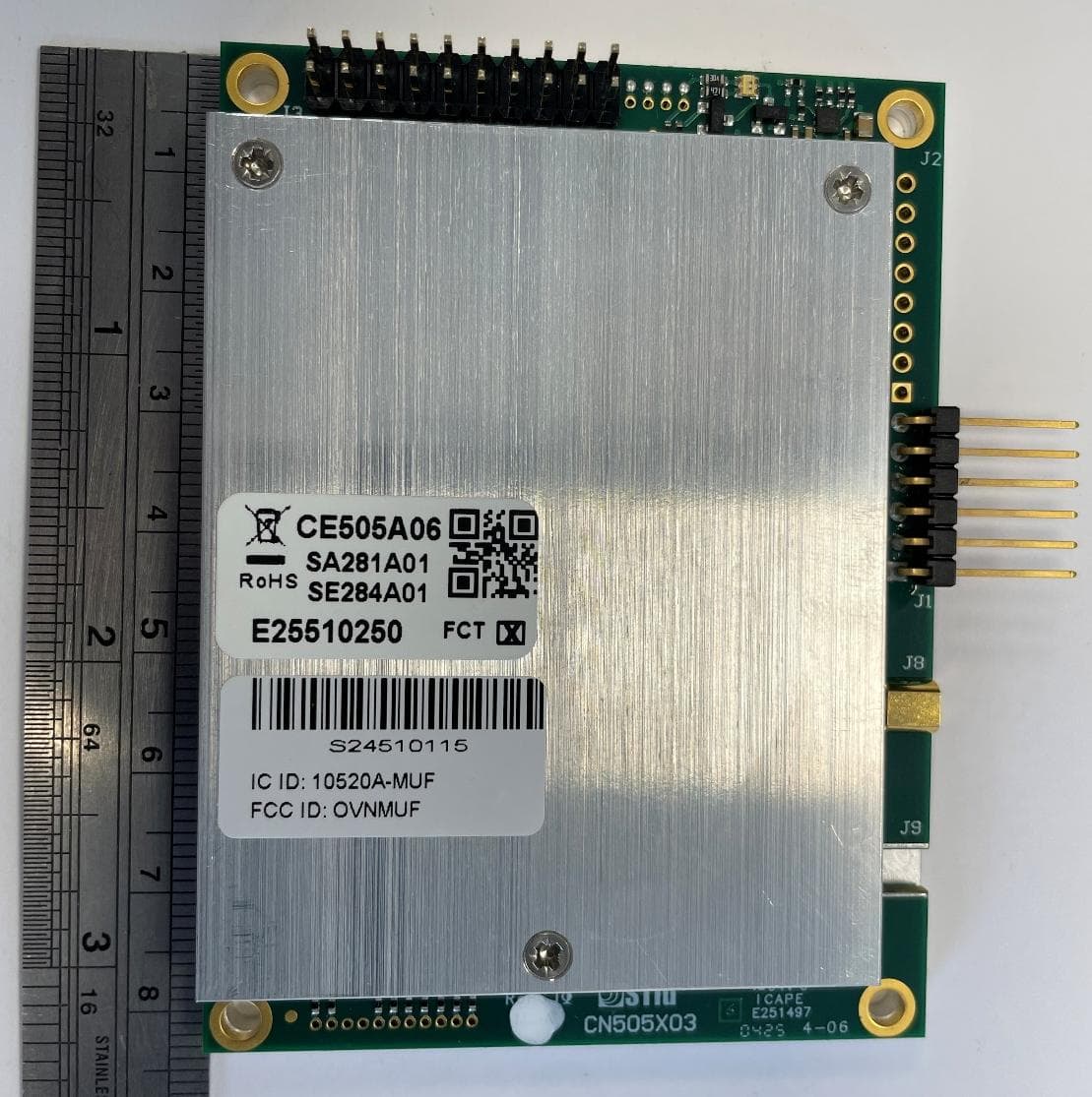
OVNMUF
May 07, 2026RFID radio module
Equipment Class
DSS - Part 15 Spread Spectrum Transmitter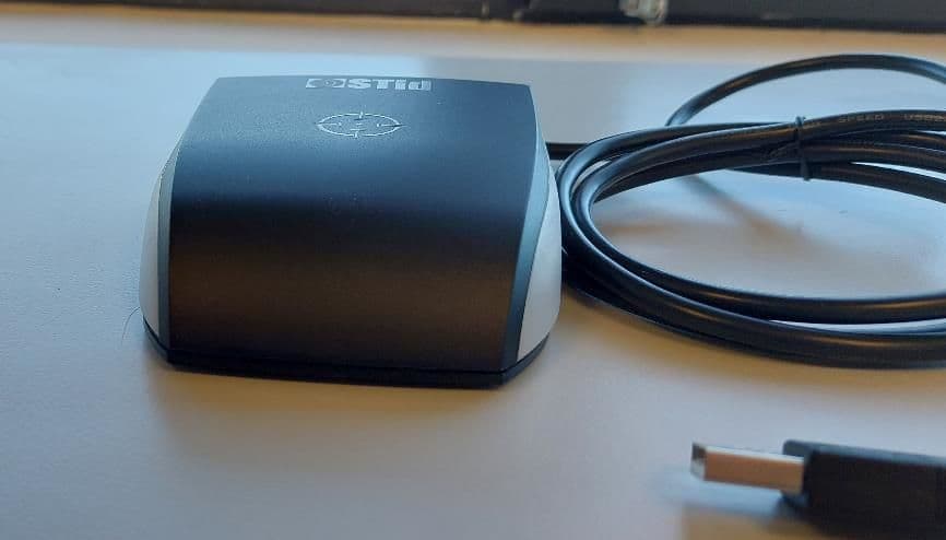
OVNAC9
Mar 26, 2023RFID communication between reader (i.e., ARC W55) and passive tag by using an UHF Carrier (902MHz to 928MHz)
Equipment Class
DSS - Part 15 Spread Spectrum Transmitter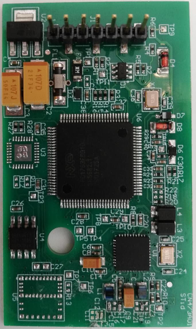
OVNAC7
May 14, 2020OEM card reader use to control access with NFC
Equipment Class
DXX - Part 15 Low Power Communication Device Transmitter