OW9ATR430PAutomobile Tag Reader
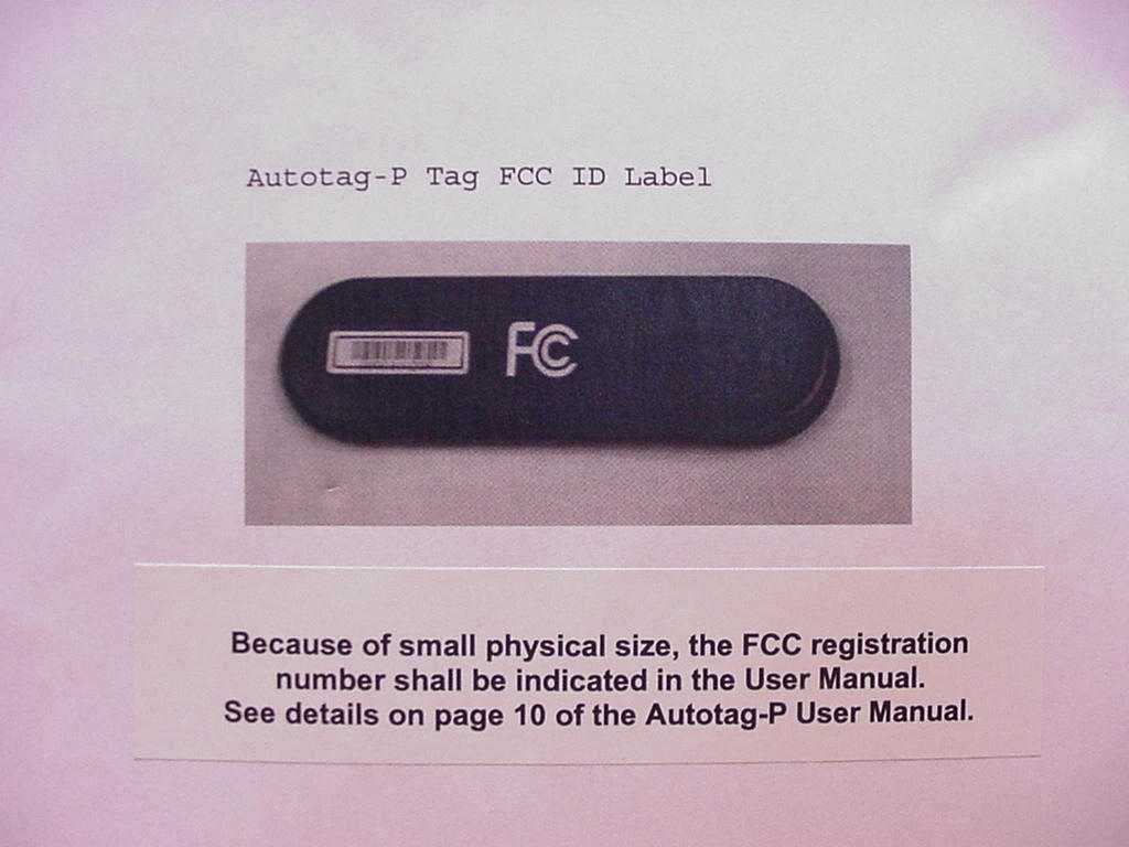
Nortech International (PTY) LTD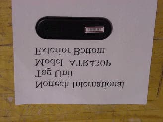
Click to zoom
Application Details
- Equipment Class
- DSC - Part 15 Security/Remote Control Transmitter
- Date of Grant
- Dec 04, 2000
- Application Purpose
- Original Equipment
- Date of Application
- Mar 13, 2000
- Equipment Note
- Automobile Tag Reader
- Frequency Range
- 433.92000000 - 433.92000000
- Country
- South Africa
Documents & Files
Document Text
Text extracted from the exhibit documents filed with the FCC. Open a document above to read the original.
Users Manual
708LF0212-AB November 1999 Autotag-P Tag McGann Installation Guide Page 1 of 1 708LF0212-AB November 1999 Autotag-P Tag McGann Installation Guide Page 1 of 1 McGann TechnologiesTel: (612) 331 2020 651 Taft Street NEFax: (612) 331 5187 Minneapolis MN 55413 McGANN TECHNOLOGIES McGann TechnologiesTel: (612) 331 2020 651 Taft Street NEFax: (612) 331 5187 Minneapolis MN 55413 McGANN TECHNOLOGIES AUTOTAG-P TAG McGANN INSTALLATION GUIDE General The Tag is an active transponder designed to communicate with an Autotag-P Base-Station unit. The Tag is triggered by the base-station when within range and transmits a unique code back. It is available in an impact- and UV-resistant nylon-based housing. It operates over a temperature range of -30°C to +85°C and has a minimum working life of 3 years. (Replacement battery CR2032 3V lithium coin cell Nortech P/No MIE040001). It is recommended that an optional Tag holder (708MD0012), which allows for the removal of the Tag from the vehicle, be used to hold the Tag in position on the windshield (windscreen). NB:Immersion of the Tag in liquid or interfering with the interior electronics will result in the warranty being voided. Positioning 1. For reliable operation the Tag should be positioned on the side of the vehicle closest to the Base Station. If, on entry or exit, the Base Station is on opposite sides of the vehicle position the Tag at the centre of the windshield behind the rear-view mirror (see Figure 1). Ensure that the driver’s field of view is not obstructed. 2. The Tag is NOT to be placed on the exterior of the vehicle. Figure 1. Tag placement on windshield (viewed from inside). Factors influencing selection of the Tag mounting position: • The main factor affecting performance is the proximity of metal or other conducting material (such as the human body). For example, many dashboards are made of metal and covered with a thin synthetic foam/rubber layer. If the Tag were placed on this it would not operate. Likewise, if placed in a person’s shirt pocket operation could also not be guaranteed. • Also, if it were placed further within the car (instead of on the windscreen) the metal shell (of the car) will act as a shield, possibly preventing communication with the Base-Station. Mounting 1. Use double sided mirror tape to mount the Tag or the optional holder. 2. Ensure that the windscreen is thoroughly clean and dry, being free of any oil or grease. 3. Remove the backing from the adhesive tape on the Tag or the optional holder and press firmly in place. 4. If the optional Tag holder is used, insert the Tag into the holder. AUTOTAG-P TAG McGANN INSTALLATION GUIDE General The Tag is an active transponder designed to communicate with an Autotag-P Base-Station unit. The Tag is triggered by the base-station when within range and transmits a unique code back. It is available in an impact- and UV-resistant nylon-based housing. It operates over a temperature range of -30°C to +85°C and has a minimum working life of 3 years. (Replacement battery CR2032 3V lithium coin cell Nortech P/No MIE040001). It is recommended that an optional Tag holder (708MD0012), which allows for the removal of the Tag from the vehicle, be used to hold the Tag in position on the windshield (windscreen). NB:Immersion of the Tag in liquid or interfering with the interior electronics will result in the warranty being voided. Positioning 1. For reliable operation the Tag should be positioned on the side of the vehicle closest to the Base Station. If, on entry or exit, the Base Station is on opposite sides of the vehicle position the Tag at the centre of the windshield behind the rear-view mirror (see Figure 1). Ensure that the driver’s field of view is not obstructed. 2. The Tag is NOT to be placed on the exterior of the vehicle. Figure 1. Tag placement on windshield (viewed from inside). Factors influencing selection of the Tag mounting position: • The main factor affecting performance is the proximity of metal or other conducting material (such as the human body). For example, many dashboards are made of metal and covered with a thin synthetic foam/rubber layer. If the Tag were placed on this it would not operate. Likewise, if placed in a person’s shirt pocket operation could also not be guaranteed. • Also, if it were placed further within the car (instead of on the windscreen) the metal shell (of the car) will act as a shield, possibly preventing communication with the Base-Station. Mounting 1. Use double sided mirror tape to mount the Tag or the optional holder. 2. Ensure that the windscreen is thoroughly clean and dry, being free of any oil or grease. 3. Remove the backing from the adhesive tape on the Tag or the optional holder and press firmly in place. 4. If the optional Tag holder is used, insert the Tag into the holder. Recommended greater than 50mm (2 inches) from the edge. Recommended mounting zones Recommended greater than 50mm (2 inches) from the edge. Recommended mounting zones
Users Manual
Nortech International (Pty) Ltd P O Box 409932A Wiganthorpe Road Willowton Hub Pietermaritzburg Pietermaritzburg 3201 South Africa 3200 South AfricaReg. No. 98/10951 Tel: (033) 345 3456Int. Tel: +27 33 345 3456 Fax: (033) 394 6449Int. Fax: +27 33 394 6449 [email protected] .co.za AUTOTAG-P USER MANUAL NORTECH INTERNATIONAL (PTY) LTD All rights reserved Copyright 1999 Document No: 708UM0210-01 Date of issue: October 1999 This document is for information only and unless otherwise indicated, is not to form part of any contract. In accordance with the manufacturer’s policy of continually updating and improving design, specifications contained herein are subject to alteration without notice. APPROVALS Originator L. Grove / M.T. Maggs Checked:______________________________ Date: __________________ Engineering Manager:_____________________________ Approved:______________________________ Date: __________________ Marketing:_____________________________ Checked and approved:______________________________ Date: __________________ Date: dd/mm/yyRevCRN No. 22/07/98000451 15/09/99010640 708UM0210-01 October 1999Autotag-P User ManualPage: 2 of 35 Table of Contents 1.INTRODUCTION...........................................................................................................................4 2.TECHNICAL DATA.......................................................................................................................6 2.1.System Parameters................................................................................................................6 2.2.Autotag-P Base Station ATR430P series................................................................................6 2.2.1.Electrical...........................................................................................................................6 2.2.2.Mechanical.......................................................................................................................6 2.2.3.Environmental..................................................................................................................6 2.2.4.RF Channel......................................................................................................................6 2.2.5.Communications...............................................................................................................7 2.2.6Relay Outputs...................................................................................................................7 2.3.Autotag-P Tag Transponder AT430P......................................................................................8 2.3.1.Electrical...........................................................................................................................8 2.3.2.Mechanical.......................................................................................................................8 2.3.3.Environmental..................................................................................................................8 2.3.4. RF Channel......................................................................................................................8 2.3.5. Code................................................................................................................................9 2.4.Autotag-P Tag with Proximity Transponder.............................................................................9 3.FCC REGULATIONS..................................................................................................................10 4.OPERATING PRINCIPLES.........................................................................................................11 4.1.Radio Frequency Communications: Important concepts.......................................................11 4.1.2.Reflection and absorption...............................................................................................12 4.1.3.Noding and nulls.............................................................................................................12 4.1.4.Radiation pattern............................................................................................................13 4.2.Autotag-P Communications Architecture...............................................................................14 4.3.Coding..................................................................................................................................14 4.3.132 Bit User Data (Tag only)............................................................................................14 4.3.216 Bit Installer Code.......................................................................................................15 4.3.38 Bit Distributor / OEM Code..........................................................................................15 4.3.432 Bit Mask (Base Station Only).....................................................................................15 4.4R.F. Communications between Base Station and Tag..........................................................15 4.4.1.Poll from the Base Station..............................................................................................15 4.4.2Response from the Tag..................................................................................................15 4.4.3Acknowledge from the Base Station...............................................................................15 4.5.Communication Protocol Options..........................................................................................16 4.5.1Wiegand Communication Protocol..................................................................................16 4.5.2Clock&Data Communication Protocol.............................................................................16 4.5.3RS-232 – Autotag-P Point-to-point Communication Protocol..........................................17 4.5.4RS-485 – Nortech …
Text truncated - open the document above for the full version.
Attestation Statements
Directors: R W Keeble (Managing), B A Lee (Financial), BJ Gnodde, B Moshal Nortech International (Pty) Ltd 32A Wiganthorpe Road Pietermaritzburg 3201 South Africa Reg. No. 98/1095 Tel: (033) 3453456 P O Box 4099 Int. Tel: +27 33 3453456Willowton Hub Telefax: +27 33 39464493200 South Africa Website: http://www.nortech.co.za The Chief Office of Engineering and Technology Federal Communications Committee 445 12th St SW. Washington DC 20554 Authorization of Underwriters Laboratories Inc. as Agent Dear Sir I hereby authorize Underwriters Laboratories Inc. to act for and on behalf of Nortech International (Pty) Ltd. as agent for registration of the Nortech AutoTag system with the FCC. I hope that this meets your approval. Kind Regards Gerrit J Loubser Engineering Manager Nortech International
Operational Description
Nortech International (Pty) Ltd P O Box 40993 2A Wiganthorpe Road Willowton Hub Pietermaritzburg Pietermaritzburg3201 South Africa 3200 South AfricaReg. No. 98/1095 Tel: (033) 34533456Int. Tel: +27 33 345 3456 Fax: (033) 394 6449int. Fax: +27 33 394 6449 E-mail: [email protected]: www.nortech.co.za AUTOTAG-P TECHNICAL DATA & CIRCUIT DESCRIPTION NORTECH INTERNATIONAL (PTY) LTD All rights reserved Copyright © 1999 Document No.: 708TD0001-01 Date of issue: October 1999 APPROVALS Originator:M.Maggs Checked:______________________________ Date: __________________ Engineering Manager:_____________________________ Approved:______________________________ Date: __________________ Marketing:_____________________________ Checked and approved: ______________________________ Date: __________________ This document is for information only and unless otherwise indicated is not to form part of any contract. In accordance with the manufacturer’s policy of continually updating and improving design, specifications contained herein are subject to alteration without notice. 708TD0001-01Autotag-P Technical DataPage: 2 of 6 Table of Contents 1.Base-station.......................................................................................................3 1.1Power Supply................................................................................................3 1.2Transmitter....................................................................................................3 1.3Receiver........................................................................................................4 1.4Microcontroller...............................................................................................4 2.TAG.....................................................................................................................5 2.1Receiver........................................................................................................5 2.2Transmitter....................................................................................................5 2.3Microprocessor..............................................................................................6 2.4Power Supply................................................................................................6 708TD0001-01Autotag-P Technical DataPage: 3 of 6 1.BASE-STATION 1.1Power Supply L10/L12and associated circuitry provide power supply filtering. For DC operation, C28 is replaced with a wire link, and D13/C43/U8 are populated. 1.2Transmitter The transmitter consists of a Colpitts oscillator, followed by an amplifier, a RF switch and variable attenuator and then the antenna connector. Colpitts oscillator Q1 is the oscillator transistor. C10 & C13 control feedback. Resonance is mainly determined by these and C11/L2. The oscillation is tapped above L2 and fed to the RF amplifier. The tapping ensures minimal loading of the oscillator by the amp (when switched on/off). The oscillator is switched on by holding TX ON high. This switches Q3 on, grounding the emitter of Q1. R9 determines oscillator current consumption and drive. F1 locks the frequency. C6 is a RF ground, helping to prevent RF from being injected onto the power line. RF amplifier Modulation is controlled via MODULATION. Q4-6 switch the RF amplifier on/off. Q5 is configured as a diode, and together with Q4 acts as a switch for the amplifier. V R14 follows V R11 at all times, thus acting as a current source to Q2. This configuration allows amp Q2 to be operated with the emitter grounded directly, with the current source preventing current variation due to V BE changes. Direct grounding is required to provide the voltage swing for 10 mA output. C7 & C2 provide a capacitive match to 50Ω. These together with C15 and L1 determine resonance. L4 & C8 act as harmonic suppression. Attenuator /switch Q8 is a temperature-compensated current source, which feeds attenuator diode D16 through RF chokes L13 & L14. Diode D1, together with the ¼-wave microstrip and D12, forms the antenna switch. It is controlled via ANT SWITCH / R15 / R12. Antenna input L3 & C9, as well as L9 and C5 are additional harmonic suppression. When tuning the Base- Station, C5 & C9 are the first trimmed for maximum transmit power, followed by C15. Once this is done the receiver capacitors C36 & C47 can be tuned for maximum sensitivity. 708TD0001-01Autotag-P Technical DataPage: 4 of 6 Antenna This is a circularly-polarised patch antenna designed for use on FR4 substrate (standard PCB material). Patches are by nature very high-Q devices, and this can result in matching problems, since etching and PCB tolerances can shift f o . To counter this, it was designed to be relatively broadband in its response (±10MHz BW). This affects the polarisation and as such, becomes elliptical. 1.3Receiver The RF input is at D12. Resistors R29, R31 and R32 form the pi-attenuator. C33 matches the chip input to 50Ω. C36/L6 filters the input signal. Chip Architecture The signal is fed into a RF amp, the resonant collector circuit of which is C47/L8. From here the signal then goes into the mixer (through C42), where it is mixed with 433.6 MHz (generated from the crystal using the PLL). The output goes into an IF filter (through C46) and IF amplifiers. It then goes into an adaptive threshold, of which R34 & C35 form the level- following filter. The output of this is the data stream. Varactor D14 together with C37/38/L7 forms the resonant circuit of a differential RF VCO. R33/36 form the bias control to the varactor, and R37/C48 in addition act as LP PLL loop filter. The output of the VCO is fed into the mixer as described above. Note: The receiver IF is very low, centred at ±300kHz. This ensures that the image has to be in the operating band, reducing the chance of interference due to image frequency. 1.4Microcontroller Communications Refer to the manual for a list of supported communications protocols. U1 is deployed for RS232 communications. …
Text truncated - open the document above for the full version.
Parts List/Tune Up Info
AUTOTAG SERVICE AND ALLIGNMENT PROCEDURES Both the Base Station and the Tag units are NOT field serviceable items and as such all service and alignment will be carried out at the factory. The units will undergo the same procedures as a production unit. See the PRODUCTION TEST PROCEDURES, section R. Parts List For Tag Bill of Material for C:\MikeMaggs\Projects\Autotag\TAG\SCH\708CD0210_00\708CD0210_S01_00.Sch Used Part Type Designator Footprint Description ==== ========= ==================== ================= ================================================= 1 302SL0100 LBL6 LABEL Label - "NORTECH" outside of cardboard box Rev ?? 1 708AW0210 PCB1 PCB_FOR_BOM PCB AutoTag DP TAG 1 708FP0003 LBL1 LABEL Label - "NORTECH" for AutoTag TAG Printed 1 708LF0001 LF1 LABEL Leaflet - AutoTag TAG Installation Instructions 1 708MD0004 H1 HOUSING-TAG-TOP Housing - AutoTag TAG Top 1 708MD0005 H2 HOUSING-TAG-BOT Housing - AutoTag TAG Bottom 1 708MD0006 H3 LABEL Housing - OPTIONAL AutoTag TAG Clip 1 708SL0210 LBL2 LABEL Label - 708FT0210 Barcode S/No 1 CXL103276 X1 XTAL206 Crystal 32K768Hz Series Resonant CL=?? pF 1 MIE040001 BT1 BTY-CR2032 Battery 3V Lithium Button cell CR2032 1 MIE130001 BTH1 BTY-HLD-CR2032 Battery Holder CR2032 SMD 13 Not Used FD1 FD2 FD3 FD4 JP1 TEST-PAD TEST PAD for BEDofNAILS L3 L4 TP1 TP2 TP3 TP4 TP5 U2 1 SC0033103 C20 0805 Capacitor 10nF Ceramic 10% 6 SC0033104 C19 C21 C22 C23 C24 0805 Capacitor 100nF Ceramic X7R 10% C25 1 SC0033222 C30 0805 Capacitor 2n2F 50V Ceramic X7R 10% 7 SC0033473 C10 C11 C12 C13 C14 0805 Capacitor 47nF Ceramic X7R 10% C15 C9 1 SC10131P0 C29 0805 Capacitor 1p0F Ceramic NPO +/- 0.25pF 1 SC10132P7 C17 0805 Capacitor 2p7F Ceramic NPO +/- 0.25pF 1 SC10133P3 C18 0805 Capacitor 3p3F Ceramic NPO +/- 0.25pF 1 SC10134P7 C27 0805 Capacitor 4p7F Ceramic NPO +/- 0.25pF 1 SC1023120 C28 0805 Capacitor 12pF 50V Ceramic NPO 5% 2 SC1023150 C1 C2 0805 Capacitor 15pF Ceramic NPO 5% 3 SC1023221 C5 C6 C8 0805 Capacitor 220pF Ceramic NPO 5% 2 SC1033102 C16 C7 0805 Capacitor 1n0F NPO Ceramic 10% 2 SC4140106 C3 C4 1206 Capacitor 10uF 10V Ceramic Y5V 20% 1 SD0400001 D1 SOT-23 Diode Schottky HSMS-2810 1 SI2151001 U1 SO-8W IC Microcontroller PIC12LCE519-04I/SM 1 SL0002331 L2 0805 Inductor Air core 330nH SMD 1 SL0002680 L1 0805 Inductor 68nH Air core SMD 1 SO2043392 SAW1 QCC-8 SAW Resonator 433.92 MHz 1-port SMD 1 SR0001155 R26 0805 Resistor 1M5 1/8W Thick Film Chip 1% 1 SR0001225 R27 0805 Resistor 2M2 1/8W Thick Film Chip 1% 16 SR0001475 R1 R10 R12 R13 R14 0805 Resistor 4M7 1/8W Thick Film Chip 1% R15 R2 R21 R22 R3 R4 R5 R6 R7 R8 R9 1 SR0003000 R35 0805 Resistor 0R 1/8W Thick Film Chip 6 SR0003103 R17 R28 R29 R30 R31 0805 Resistor 10K 1/8W Thick Film Chip R33 1 SR0003104 R18 0805 Resistor 100K 1/8W Thick Film Chip 1 SR0003185 R16 0805 Resistor 1M8 1/8W Thick Film Chip 5% 2 SR0003204 R23 R25 0805 Resistor 200K 1/8W Thick Film Chip 5% 1 SR0003275 R11 0805 Resistor 2M7 1/8W Thick Film Chip 5% 2 SR0003470 R19 R20 0805 Resistor 47R 1/8W Thick Film Chip 5% 1 SR0003561 R34 0805 Resistor 560R 1/8W Thick Film Chip 5% 3 SR0003824 R24 R32 R36 0805 Resistor 820K 1/8W Thick Film Chip 5% 2 ST00BC817 Q4 Q5 SOT23-BEC Transistor BC817-40 NPN 5 ST10BFR92 Q11 Q3 Q6 Q7 Q9 SOT-23 Transistor BFR92 NPN 2 ST90BSN20 Q10 Q8 SOT-23 Transistor MOSFET N- channel Enh. BSN20 2 ST90BSS84 Q1 Q2 SOT-23 Transistor MOSFET P- channel Enh. BSS84 2 ZZA212075 S1 S2 SCREW-2.0-C/S Screw Self Tapper 2.0x?.? Countersunk 1 ZZC500004 BOX1 LABEL Packaging - TAG Cardboard box 1 ZZC801001 BOX2 LABEL Packaging - Packaging - TAG Foil Screen 1 ZZJ503001 LBL3 LABEL Tape Double Sided 6mm X 50mm
Test Report
Sample Ticket Number: «Sample_Ticket_Number» Date Sample(s) Received: «Date_Sample_Recieved» Page 1 of 12 Underwriters Laboratories Inc. 1285 Walt Whitman Rd. Melville, New York 11747 USA Tel.: 631 271-6200 Fax: 631 439-6095 Rev. No 1.3 Underwriters Laboratories Inc. 1285 Walt Whitman Road Melville, New York 11747-3081 (516) 271-6200 Report of Measurements of Electromagnetic Compatibility Testing Test Report File No.:NC3952Date of issue: March 20, 2000 Applicant:Nortech International Model / Serial No.:ATR430P/0990409984, FCC ID: OW9ATR430P Product Type:Tag Power Supply:3V Lithium button cell Manufacturer:Same as Applicant License holder:Same as Applicant Address:32A Wiganthorpe Road :Pietermaritzburg 3201 South Africa, Test Result:x Positive® Negative Test Project Number:99ME43512 References(s) Underwriters Laboratories Inc. authorizes the above-named company to reproduce this Report provided it is reproduced in its entirety. Underwriters Laboratories Inc. reports apply only to the specific samples tested under stated test conditions. It is the manufacturer's responsibility to assure that additional production units of this model are manufactured with identical electrical and mechanical components. Underwriters Laboratories Inc. shall have no liability for any deductions, inferences or generalizations drawn by the client or others from Underwriters Laboratories Inc. issued reports. This report is the confidential property of the client. As a mutual protection to our clients, the public and ourselves, extracts from the test report shall not be reproduced except in full without our written approval. This report shall not be used by the client to claim product endorsement by NVLAP or any agency of the US government. File Number: NC3952Issued: March 13, 2000 Project Number: 99ME43512 Model Number: ATR430P/0990409984, FCC ID: OW9TR430P Page 2 of 12 Underwriters Laboratories Inc. 1285 Walt Whitman Rd. Melville, New York 11747 USA Tel.: 631271-6200 Fax: 631 439-6095 Rev. No 1.3 Report Directory TitleSection x General Product Description1.0 x Device Configuration During Test1.1 ® Deviations from ANSI C63.4 Standard Test Set-up1.1.1 ® Device Modifications1.2 x Emissions Test Regulations2.0 x Operational Mode2.1 ® Conducted Emissions (Voltage and Current)2.1.1 ® Conducted Click Emissions2.1.2 ® Reserved for Future Use2.2.1 x Radiated Emissions Test (10 Meter Semi-Anechoic Chamber)2.2.2 o RFI Power Measurements2.2.3 ® Harmonic Disturbances2.2.4 x Emissions Test Results2.3 ® Immunity Test Regulations3.0 ® Operational Mode3.1 ® Electrostatic Discharge (ESD) Test3.1.1 ® Radiated Field (RF) Test3.1.2 ® Electrical Fast Transient (EFT)/Burst Test3.1.3 ® Surge Transient Tests3.1.4 ® Conducted Immunity Tests3.1.5 ® Voltage, Dips and Interruptions3.1.6 ® Immunity Test Results3.2 x Summary of Test Results4.0 x Emissions Test Data PagesAppendix A x Photographs and DiagramsAppendix B File Number: NC3952Issued: March 13, 2000 Project Number: 99ME43512 Model Number: ATR430P/0990409984, FCC ID: OW9TR430P Page 3 of 12 Underwriters Laboratories Inc. 1285 Walt Whitman Rd. Melville, New York 11747 USA Tel.: 631271-6200 Fax: 631 439-6095 Rev. No 1.3 1.0G E N E R A L - Product Description The Device Under Test Model ATR430P, Serial Number 0990409984 is a low power Receiver/Transmitter which is intended to be placed in an automobile and used as a means of identification when approaching a toll plaza. File Number: NC3952Issued: March 13, 2000 Project Number: 99ME43512 Model Number: ATR430P/0990409984, FCC ID: OW9TR430P Page 4 of 12 Underwriters Laboratories Inc. 1285 Walt Whitman Rd. Melville, New York 11747 USA Tel.: 631271-6200 Fax: 631 439-6095 Rev. No 1.3 1.1 Device Configuration During Test The device Model ATR430P, Serial Number 0990409984 was placed on a wooden table and set to transmit continuously. "The results contained in this report reflect the results for this particular model and serial number. It is the responsibility of the manufacturer to ensure that all production models meet the intent of the requirements detailed within this report." 1.1.1Deviations from ANSI C63.4 Standard Test Set-up x None ® As described below: 1.2Device Modifications Necessary for Compliance xN/A ® As described below: Environmental conditions in the lab: Range Temperature:20-25°C Relative Humidity30 - 60 % Atmospheric pressure680 - 1060 mbar File Number: NC3952Issued: March 13, 2000 Project Number: 99ME43512 Model Number: ATR430P/0990409984, FCC ID: OW9TR430P Sample Ticket Number: «Sample_Ticket_Number» Date Sample(s) Received:«Date_Sample_Recieved» Technicians Name/Signature: __________/______________ Date test performed: _________ (print) (signature) Page 5 of 12 Date Assigned to Lab: «Date_Assigned_to_Lab» Underwriters Laboratories Inc. 1285 Walt Whitman Rd. Melville, New York 11747 USA Tel.: 631 271-6200 Fax: 631 439-6095 Rev. No 1.3 EMC TEST DATA PACKAGE For Nortech International ATR430P/0990409984, FCC ID: OW9ATR430P Tag Project Number: 99ME43512 File NumberNC3952 Reviewer:Bob DeLisi/____________ (Signature) File Number: NC3952Issued: March 13, 2000 Project Number: 99ME43512 Model Number: ATR430P/0990409984, FCC ID: OW9TR430P Sample Ticket Number: «Sample_Ticket_Number» Date Sample(s) Received:«Date_Sample_Recieved» Technicians Name/Signature: __________/______________ Date test performed: _________ (print) (signature) Page 6 of 12 Date Assigned to Lab: «Date_Assigned_to_Lab» Underwriters Laboratories Inc. 1285 Walt Whitman Rd. Melville, New York 11747 USA Tel.: 631 271-6200 Fax: 631 439-6095 Rev. No 1.3 2.0 EMISSIONS TEST REGULATIONS: o EN 50081-1 /1992 o EN 50081-2 /1993 o EN 55011 / 3.1991® Group 1o Group 2 ® Class Ao Class B o EN 55011/1998o Group 1o Group 2 o Class Ao Class B o EN 55013 / 6.1990 o EN 55013/1997 o EN 55014–1: 1997o Household appliances and similar o Portable tools o Semiconductor devices o EN 55015 / 1993 o EN 55020 / 1995 ®EN 55022 / 4.1998o Class A®Class B ® EN60555-2/1987, EN60555-3/1987 ® EN60601-1-…
Text truncated - open the document above for the full version.
Contact Information
Applicant
Barry Kemp(Managing Director Components Division)
Test Firm
UL LLCBob Delisi
Technical Specifications
| # | Rule Parts | Frequency Range | Power Output | Tolerance |
|---|---|---|---|---|
| 1 | 15C | 433.92 MHz - 433.92 MHz | - | % |
Other Applications from Nortech International (PTY) LTD
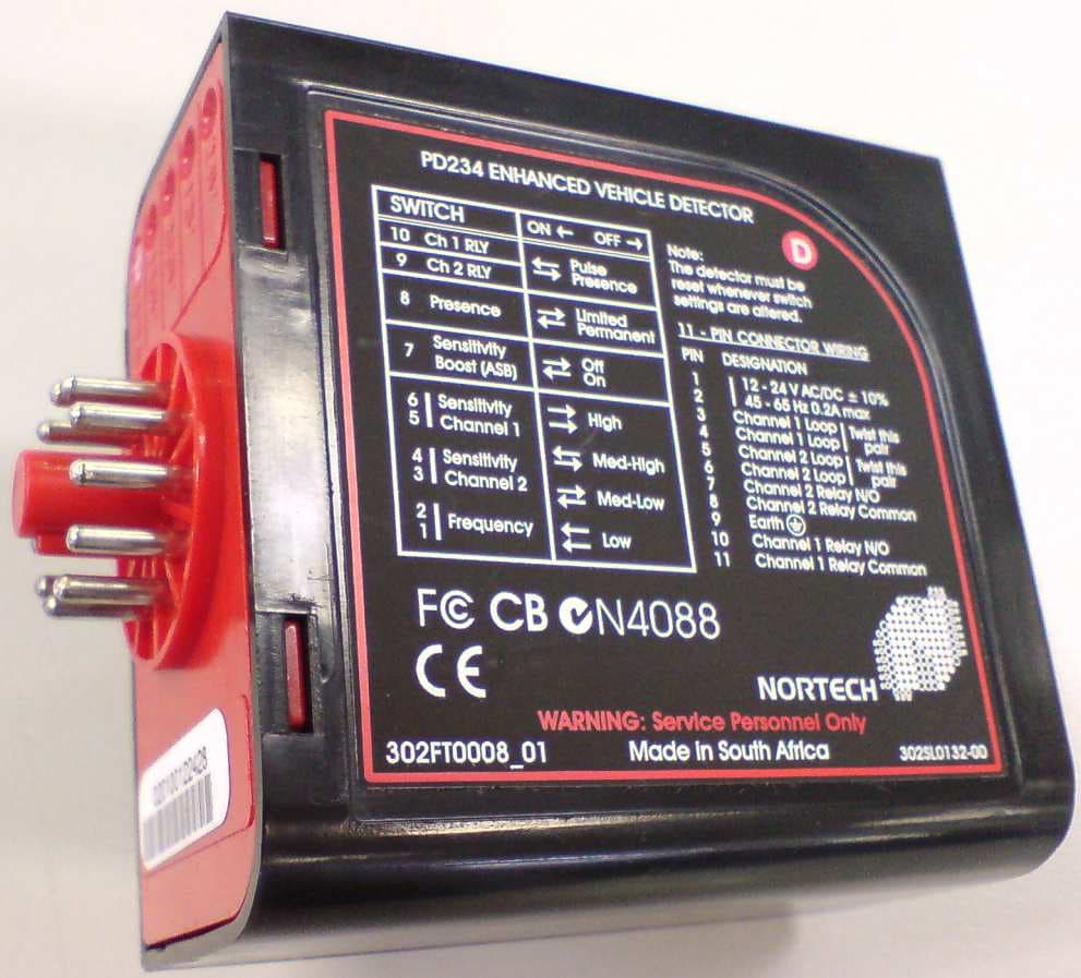
OW9PD230TD236
Sep 08, 2010Vehicle Detector
Equipment Class
DCD - Part 15 Low Power Transmitter Below 1705 kHz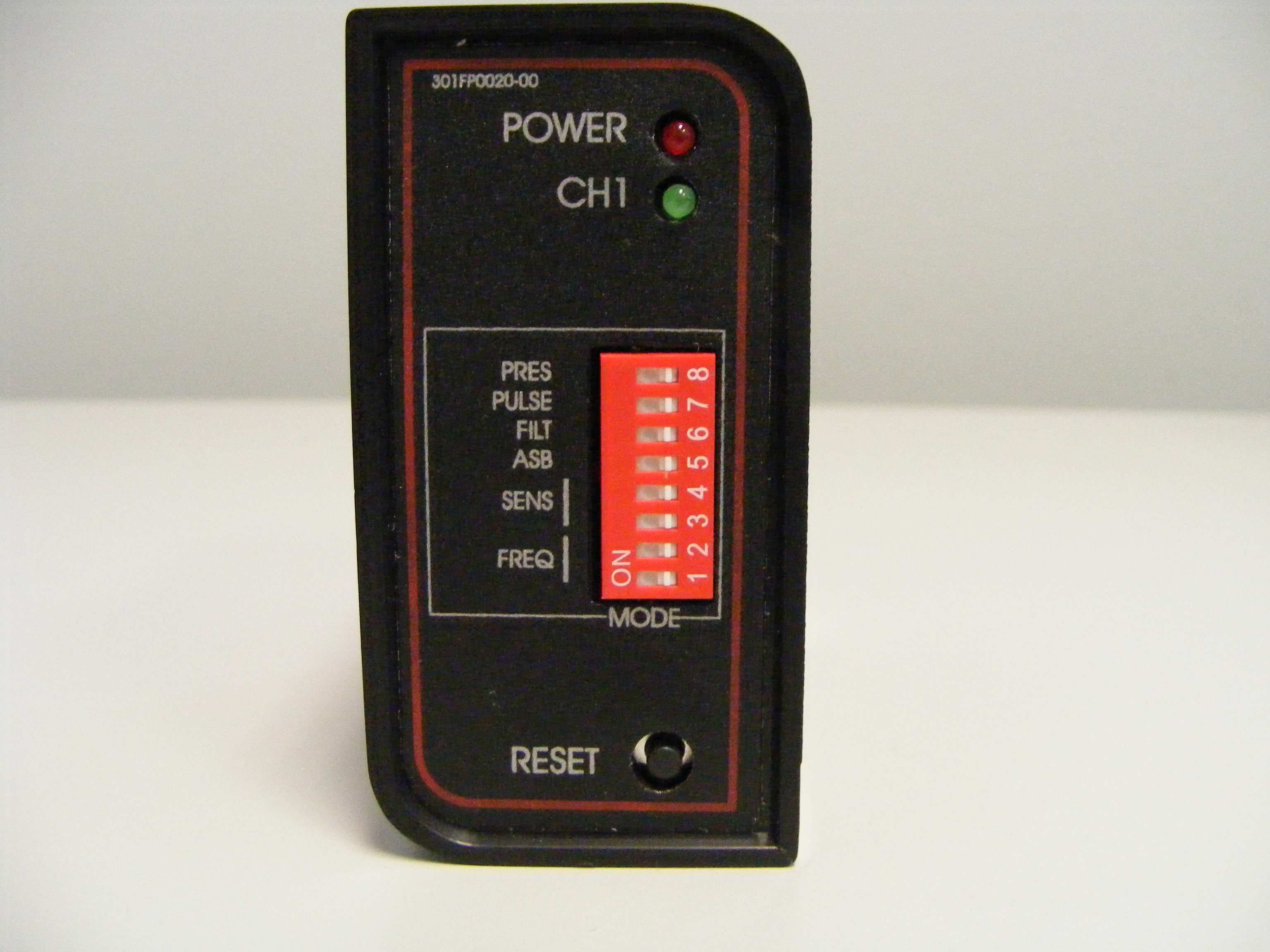
OW9PD130TD136
Sep 02, 2010Vehicle Detector
Equipment Class
DCD - Part 15 Low Power Transmitter Below 1705 kHz
OW9ATR434P
Dec 04, 2000Autotag Base Station
Equipment Class
DSC - Part 15 Security/Remote Control Transmitter