OW9PD130TD136Vehicle Detector
Nortech International (PTY) LTD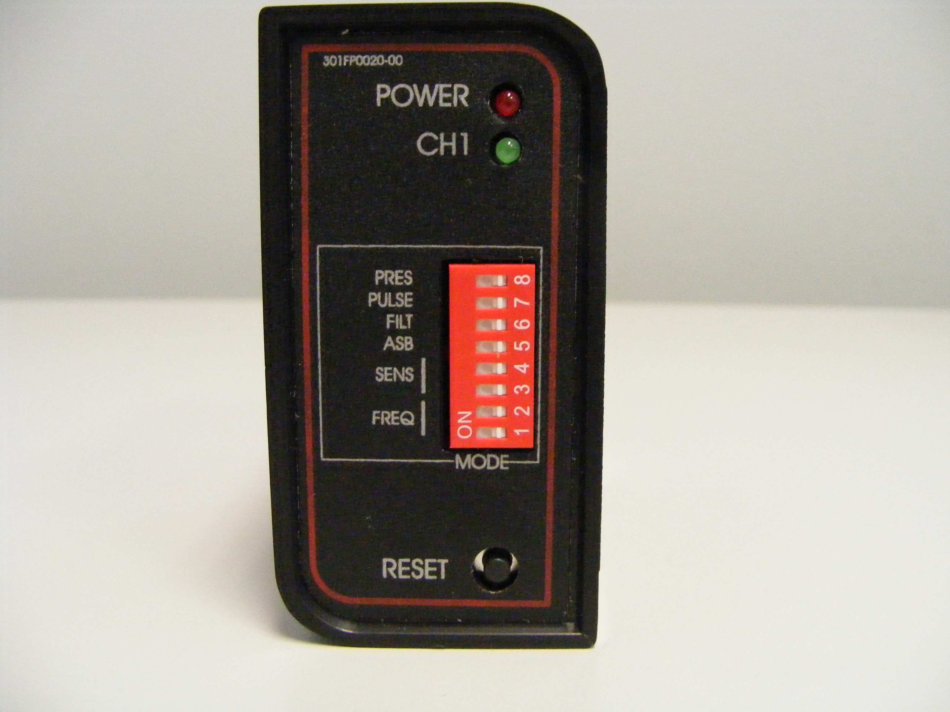
Click to zoom
Application Details
- Equipment Class
- DCD - Part 15 Low Power Transmitter Below 1705 kHz
- Date of Grant
- Sep 02, 2010
- Application Purpose
- Original Equipment
- Date of Application
- Sep 01, 2010
- Equipment Note
- Vehicle Detector
- Frequency Range
- 0.01200000 - 0.08000000
- Country
- South Africa
Documents & Files
Document Text
Text extracted from the exhibit documents filed with the FCC. Open a document above to read the original.
Users Manual
Nortech International (Pty) Ltd PO Box 4099 32A Wiganthorpe Road Willowton Hub Pietermaritzburg Pietermaritzburg 3201 South Africa 3200 South Africa Reg. No: 98/1095 Tel: (033) 345 3456 Int. Tel: +27 33 345 3456 Fax: (033) 394 6449 Int. Fax: +27 33 394 6449 Email: [email protected] URL: www.nortech.co.za PD130 Enhanced Vehicle Detector User Manual NORTECH INTERNATIONAL (PTY) LTD All rights reserved Copyright © 2009 Document Number: 301UM0030_01 Date of Issue: September 2009 This document is for information only and unless otherwise indicated, is not to form part of any contract. In accordance with the manufacturer’s policy of continually updating and improving design, specifications contained herein are subject to alteration without notice. 301UM0030_01 PD130 Enhanced Vehicle Detector User Manual Page: 2 of 29 Table of Contents 1. INTRODUCTION........................................................................................................................................5 2. TECHNICAL DATA ...................................................................................................................................6 2.1 Functional Data ......................................................................................................................................6 2.2 Electrical Data ........................................................................................................................................7 2.3 Environmental Data ................................................................................................................................7 2.4 Mechanical Data .....................................................................................................................................7 2.5 Approvals................................................................................................................................................8 3. OPERATING PROCEDURE......................................................................................................................9 3.1 Hardware Set-Up ....................................................................................................................................9 3.2 Switch Setting Selections .......................................................................................................................9 3.2.1 Frequency Switch............................................................................................................................9 3.2.2 Sensitivity ......................................................................................................................................10 3.2.3 Automatic Sensitivity Boost ...........................................................................................................10 3.2.4 Filter Mode ....................................................................................................................................10 3.2.5 Pulse Relay ...................................................................................................................................10 3.2.6 Presence Time ..............................................................................................................................10 3.2.7 Reset Switch .................................................................................................................................11 3.3 Power Fail (Option)...............................................................................................................................11 3.4 Front Panel Indicator ............................................................................................................................11 4. PRINCIPAL OF OPERATION .................................................................................................................12 4.1 Detector Tuning ....................................................................................................................................12 4.2 Detector Sensitivity...............................................................................................................................12 4.3 Modes of Operation ..............................................................................................................................13 4.4 Response Times...................................................................................................................................13 5. INSTALLATION GUIDE ..........................................................................................................................14 5.1 Product Safety Requirements...............................................................................................................14 5.2 Operational Constraints........................................................................................................................14 5.2.1 Environmental Factors to Consider...............................................................................................14 5.2.2 Crosstalk.......................................................................................................................................15 5.2.3 Reinforcing....................................................................................................................................15 5.3 Loop and Feeder Specification.............................................................................................................15 5.4 Sensing Loop Geometry.......................................................................................................................16 5.5 Loop Installation ...................................................................................................................................16 6. CONFIGURATION ...................................................................................................................................18 6.1 PD131 Enhanced Detector - Or…
Text truncated - open the document above for the full version.
Cover Letter(s)
TÜV Rheinland EPS B.V. Smidshornerweg 18 P.O. Box 15 9822 ZG Niekerk The Netherlands www.tuv-eps.com T +31 594 505005 F +31 594 504804 E [email protected] Subject Antenna info Date August 04, 2010 Our reference -- Your reference -- Page 1 of 1 Our General Terms and Conditions, as filed at the Chamber of Commerce in Groningen, are applicable to all orders given to TÜV Rheinland EPS B.V. TÜV Rheinland EPS B.V. is registered at the Chamber of Commerce in Groningen with no. 27247331. ® TÜV, TUEV and TUV are register ed trademarks. Utilisation and app lication requires prior approval. Return address: P.O. Box 15, 9822 ZG Niekerk, The Netherlands ATCB Attn.: Mrs. M. Bosley Certification Department 6731 Whittier Avenue, Suite C110 McLean, Virginia 22101 USA Dear Mrs. Bosley, On behalf of our customer Nortech International (Pty) Ltd, we hereby declare that the antenna of the following device: FCC ID : OW9PD130TD136 Brand : Nortech Model : PD130 / TD136 family Description : Enhanced single channel inductive vehicle detector operating in the range 12–80 kHz Antenna Gain: Not applicable Is an inductive loop coil. A loop of two or more turns of wire, layed under the road or pavement surface. This loop of wire is connected to the detector by a twisted pair of wires called a loop feeder. Best regards, TÜV Rheinland EPS B.V. R. van der Meer Test Engineer
External Photos
PD130/TD136 Enhanced Family – External Photo’s Rev AA Page 1 of 5 PD130 / TD136 Enhanced Family of Single Channel Inductive Loop Vehicle Detectors- External Photos PD131, PD132 & PD134 Front View PD130/TD136 Enhanced Family – External Photo’s Rev AA Page 2 of 5 PD13x Side View PD130/TD136 Enhanced Family – External Photo’s Rev AA Page 3 of 5 TD134 &TD136 Front View PD130/TD136 Enhanced Family – External Photo’s Rev AA Page 4 of 5 TD13x Side View PD130/TD136 Enhanced Family – External Photo’s Rev AA Page 5 of 5 Side View showing embossed Logo All Models – Rear View showing connector (white dot indicate operating voltage)
ID Label/Location Info
PD130/TD136 Enhanced Family – Label Information – Rev AB Page 1 of 5 PD130 / TD136 Enhanced Family of Single Channel Inductive Loop Vehicle Detectors Label Information PD131, PD132 & PD134 Front View PD131 Side View PD130/TD136 Enhanced Family – Label Information – Rev AB Page 2 of 5 PD132 Side View PD134 Side View PD130/TD136 Enhanced Family – Label Information – Rev AB Page 3 of 5 TD134 & TD136 Front View TD13x Side View PD130/TD136 Enhanced Family – Label Information – Rev AB Page 4 of 5 All Models – Rear View showing connector (white dot indicate operating voltage) Example of Language change and OEM Branding PD130/TD136 Enhanced Family – Label Information – Rev AB Page 5 of 5 Example of Packaging Labeling
Internal Photos
PD130/TD136 Enhanced Family – Internal Photos Rev AA Page 1 of 5 PD130 / TD136 Enhanced Family of Single Channel Inductive Loop Vehicle Detectors - Internal Photos 120 V & 230 V Models – Interior Top View PD130/TD136 Enhanced Family – Internal Photos Rev AA Page 2 of 5 120 V & 230 V Models – Interior Front View PD130/TD136 Enhanced Family – Internal Photos Rev AA Page 3 of 5 12/24V Models – Interior Top View PD130/TD136 Enhanced Family – Internal Photos Rev AA Page 4 of 5 12/24V Models – Interior Front View PD130/TD136 Enhanced Family – Internal Photos Rev AA Page 5 of 5 All models – Interior Bottom of PCB
Test Report
Testing and certification of, consultancy and research concerning, electronic and electric appliances, systems, installations and telecommunication systems TÜV Rheinland EPS B.V. P.O. Box 15 9822 ZG Niekerk (NL) Smidshornerweg 18 9822 TL Niekerk (NL) Telephone: +31 594 505005 Telefax: +31 594 504804 E-mail: [email protected] Web: www.tuv-eps.com Project number: 10051001.fcc01 Page 1 of 19 TEST REPORT CONCERNING THE COMPLIANCE OF AN INDUCTIVE LOOP VEHICLE DETECTOR, BRAND NORTECH , MODEL PD131 AND PD134 WITH 47 CFR PART 15 (10-1-09 Edition) FCC ID: OW9PD130TD136 10051001.fcc01 August 30, 2010 FCC listed Industry Canada VCCI Registered R&TTE, LVD, EMC Notified Body : : : : 90828 2932G-1 R-1518, C-1598 1856 Test specification(s): Description of EUT: Manufacturer: Brand mark: Model: FCC ID: FCC Part 15 Inductive Loop Vehicle Detector Nortech International (Pty) Ltd. Nortech PD131 and PD134 OW9PD130TD136 Project number : 10051001.fcc01 Page 2 of 19 MEASUREMENT/TECHNICAL REPORT Model Summary: This report covers only 2 transmitter models – the applicant states: differences are explained within the Attestation of Similarity found in Appendix 1. All models incorporate the identical circuitry and integral RF Section and PWB embedded antenna housed on the device. From all product geometric differences the worst case units were tested and shown in this report. Refer to Appendix 1 for more information. Brand: Nortech Model : PD131 and PD134 FCC ID: OW9PD130TD136 August 30, 2010 This report concerns: Original grant/certification Class 2 Permissive Change Verification Equipment type: DSC - Part 15 Security/Remote Control Transmitter Report prepared by: Name : Richard van der Meer Company name : TÜV Rheinland EPS B.V. Address : Smidshornerweg 18 Postal code/city : 9822 TL Niekerk Mailing address : P.O. Box 15 Postal code/city : 9822 ZG Niekerk Country : The Netherlands Telephone number : + 31 594 505 005 Telefax number : + 31 594 504 804 E-mail : [email protected] The data taken for this test and report herein was done in accordance with 47 CFR Part 15 (10-1-09 Edition), and the measurement procedures of ANSI C63.4-2003. TÜV Rheinland EPS B.V. at Niekerk, The Netherlands, certifies that the data is accurate and contains a true representation of the emission profile of the Equipment Under Test (EUT) on the date of the test as noted in the test report. I have reviewed the test report and find it to be an accurate description of the test(s) performed and the EUT so tested. Date: August 30, 2010 Signature: O. Hoekstra Senior Engineer Telecom TÜV Rheinland EPS B.V. Test specification(s): Description of EUT: Manufacturer: Brand mark: Model: FCC ID: FCC Part 15 Inductive Loop Vehicle Detector Nortech International (Pty) Ltd. Nortech PD131 and PD134 OW9PD130TD136 Project number : 10051001.fcc01 Page 3 of 19 Description of test item Test item (EUT) : Inductive Loop Vehicle Detector Manufacturer : Nortech International (Pty) Ltd. Brand : Nortech Model(s) : PD131 and PD134 Serial number(s) : 020100115684 (PD131) and 020100115687 (PD134) Receipt date : July 12, 2010 Applicant information Applicant's representative : Mr. Mike Maggs Company : Nortech International (Pty) Ltd. Address : 32A Wiganthorpe Road Postal code : 3201 City : Pietermaritzburg Country : South Africa Telephone number : +27 33 34553456 Telefax number : +27 33 3946449 e-mail address [email protected] Test(s) performed Location : Niekerk Test(s) started : July 28, 2010 Test(s) completed : August 18, 2010 Purpose of test(s) : Equipment Authorization (original certification) Test specification(s) : 47 CFR Part 15 (10-1-09 Edition) Test engineer(s) : R. van der Meer Report written by : R. van der Meer Report date : August 30, 2010 This report is in conformity with NEN-EN-ISO/IEC 17025: 2005 This report shall not be reproduced, except in full, without the written permission of TÜV Rheinland EPS B.V. The test results relate only to the item(s) tested. Test specification(s): Description of EUT: Manufacturer: Brand mark: Model: FCC ID: FCC Part 15 Inductive Loop Vehicle Detector Nortech International (Pty) Ltd. Nortech PD131 and PD134 OW9PD130TD136 Project number : 10051001.fcc01 Page 4 of 19 Table of contents 1 General information. .............................................................................................................................................. 5 1.1 Product description. ........................................................................................................................................ 5 1.1.1 Introduction. ............................................................................................................................................ 5 1.2 Related submittal(s) and/or Grant(s). ............................................................................................................. 5 1.2.1 General. .................................................................................................................................................. 5 1.3 Tested system details. .................................................................................................................................... 5 1.3.1 Description of input and output ports. ..................................................................................................... 7 1.4 Test methodology. .......................................................................................................................................... 7 1.5 Test facility. .................................................................................................................................................... 7 1.6 Test conditions. .............................................................................................................................................. 7 2 System test configuration. ................................................................................................................................…
Text truncated - open the document above for the full version.
Test Setup Photos
Testing and certification of, consultancy and research concerning, electronic and electric appliances, systems, installations and telecommunication systems TÜV Rheinland EPS B.V. P.O. Box 15 9822 ZG Niekerk (NL) Smidshornerweg 18 9822 TL Niekerk (NL) Telephone: +31 594 505005 Telefax: +31 594 504804 Internet: www.tuv-eps.com E-mail: [email protected] Project number: 10051001.p03 Page 1 of 10 PHOTOGRAPHS OF THE TESTSETUP OF AN INDUCTIVE LOOP VEHICLE DETECTOR, BRAND NORTECH , MODEL PD130 AND PD134 10051001.p03 August 30, 2010 FCC listed Industry Canada VCCI Registered R&TTE, LVD, EMC Notified Body : : : : 90828 2932G-1 R-1518, C-1598 1856 Description of EUT: Manufacturer: Brand mark: Model: FCC ID: Inductive Loop Vehicle Detector Nortech International (Pty) Ltd. Nortech PD130 & PD134 OW9PD130TD136 Project number: 10051001.p03 Page 2 of 10 Description of test item Test item (EUT) : Inductive Loop Vehicle Detector Manufacturer : Nortech International (Pty) Ltd. Brand : Nortech Model(s) : PD131 and PD134 Serial number(s) : 020100115684 (PD131) and 020100115687 (PD134) Receipt date : July 12, 2010 Applicant information Applicant's representative : Mr. Mike Maggs Company : Nortech International (Pty) Ltd. Address : 32A Wiganthorpe Road Postal code : 3201 City : Pietermaritzburg Country : South Africa Telephone number : +27 33 34553456 Telefax number : +27 33 3946449 e-mail address [email protected] Description of EUT: Manufacturer: Brand mark: Model: FCC ID: Inductive Loop Vehicle Detector Nortech International (Pty) Ltd. Nortech PD130 & PD134 OW9PD130TD136 Project number: 10051001.p03 Page 3 of 10 Table of contents 1 PHOTOGRAPHS OF THE TESTSETUP. ....................................................................................................................... 4 1.1 RADIATED EMISSIONS..................................................................................................................................................... 4 1.1.1 Radiated emissions H-field @ 3m of the PD131 ............................................................................................. 4 1.1.2 Radiated emissions H-field @ 3m of the PD134 ............................................................................................. 5 1.1.3 Radiated emissions E-field @3m of the PD131 .............................................................................................. 6 1.1.4 Radiated emissions E-field @3m of the PD134 .............................................................................................. 7 1.2 RADIATED EMISSIONS @3M TABLETOP SETUP .............................................................................................................. 8 2 CONDUCTED EMISSIONS ............................................................................................................................................... 9 2.1 CONDUCTED EMISSIONS SETUP FOR PD131 ................................................................................................................ 9 2.2 CONDUCTED EMISSIONS SETUP FOR PD134 .............................................................................................................. 10 .................................................................................................................................................................................................. 10 Description of EUT: Manufacturer: Brand mark: Model: FCC ID: Inductive Loop Vehicle Detector Nortech International (Pty) Ltd. Nortech PD130 & PD134 OW9PD130TD136 Project number: 10051001.p03 Page 4 of 10 1 Photographs of the testsetup. 1.1 Radiated emissions. 1.1.1 Radiated emissions H-field @ 3m of the PD131 Description of EUT: Manufacturer: Brand mark: Model: FCC ID: Inductive Loop Vehicle Detector Nortech International (Pty) Ltd. Nortech PD130 & PD134 OW9PD130TD136 Project number: 10051001.p03 Page 5 of 10 1.1.2 Radiated emissions H-field @ 3m of the PD134 Description of EUT: Manufacturer: Brand mark: Model: FCC ID: Inductive Loop Vehicle Detector Nortech International (Pty) Ltd. Nortech PD130 & PD134 OW9PD130TD136 Project number: 10051001.p03 Page 6 of 10 1.1.3 Radiated emissions E-field @3m of the PD131 Description of EUT: Manufacturer: Brand mark: Model: FCC ID: Inductive Loop Vehicle Detector Nortech International (Pty) Ltd. Nortech PD130 & PD134 OW9PD130TD136 Project number: 10051001.p03 Page 7 of 10 1.1.4 Radiated emissions E-field @3m of the PD134 Description of EUT: Manufacturer: Brand mark: Model: FCC ID: Inductive Loop Vehicle Detector Nortech International (Pty) Ltd. Nortech PD130 & PD134 OW9PD130TD136 Project number: 10051001.p03 Page 8 of 10 1.2 Radiated emissions @3m tabletop setup setup for PD131 setup for PD134 Description of EUT: Manufacturer: Brand mark: Model: FCC ID: Inductive Loop Vehicle Detector Nortech International (Pty) Ltd. Nortech PD130 & PD134 OW9PD130TD136 Project number: 10051001.p03 Page 9 of 10 2 Conducted emissions 2.1 Conducted emissions setup for PD131 Description of EUT: Manufacturer: Brand mark: Model: FCC ID: Inductive Loop Vehicle Detector Nortech International (Pty) Ltd. Nortech PD130 & PD134 OW9PD130TD136 Project number: 10051001.p03 Page 10 of 10 2.2 Conducted emissions setup for PD134
Contact Information
Applicant
Barry Kemp(Managing Director Components Division)
Technical Contact
Nortech InternationalMike Maggs
[email protected]+27 33 3453456
32A Wiganthorpe Rd. · Nierkerk · Netherlands
Test Firm
TUV Rheinland Nederland B.V.Wiebe Boekema
Technical Specifications
| # | Rule Parts | Frequency Range | Power Output |
|---|---|---|---|
| 1 | 15C | 0.012 MHz - 0.08 MHz | - |
Other Applications from Nortech International (PTY) LTD
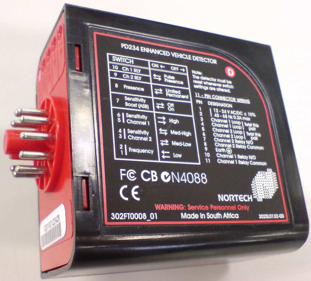
OW9PD230TD236
Sep 08, 2010Vehicle Detector
Equipment Class
DCD - Part 15 Low Power Transmitter Below 1705 kHz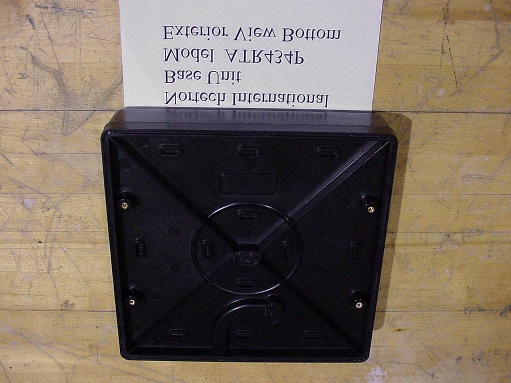
OW9ATR434P
Dec 04, 2000Autotag Base Station
Equipment Class
DSC - Part 15 Security/Remote Control Transmitter
OW9ATR430P
Dec 04, 2000Automobile Tag Reader
Equipment Class
DSC - Part 15 Security/Remote Control Transmitter