OWA00GT1Battery Powered GPS Tracking Device
Geoforce Inc.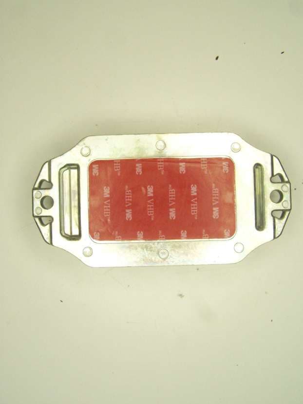
Click to zoom
Application Details
- Equipment Class
- DSS - Part 15 Spread Spectrum Transmitter
- Date of Grant
- Aug 29, 2012
- Application Purpose
- Original Equipment
- Date of Application
- Aug 29, 2012
- Equipment Note
- Battery Powered GPS Tracking Device
- Frequency Range
- 2404.00000000 - 2478.00000000
- Company
- Geoforce Inc.
- Country
- United States
Documents & Files
Document Text
Text extracted from the exhibit documents filed with the FCC. Open a document above to read the original.
Users Manual
GT-1 Basic Installation, Maintenance and User Setup Guide Guide Revision v1.1 Geoforce Inc. GT-1 Part Number: XS-GT-1 GT-1 Installation Installation Basics: The Geoforce GT-1 can be installed on any flat surface that allows a full view of the sky. A variety of (5/16” or 8 mm) installation hardware can be utilized to mount the GT-1. Socket-Head Cap Screws (for installations that do not have access to the back side of the mounting surface) Hex-Head Cap Screws (for installations that have access to the back side of the mounting surface for a nut) Self-drilling Sheet-metal Screws The GT-1 will capture and hold a Hex-Head Cap Screw while being secured from the backside. To Mount the GT-1: 1. Locate a flat surface that gives the GT-1 a good view to the sky. 2. Drill Two 5/16” diameter mounting holes 5.5” (140mm) apart. These holes may also be drilled and tapped 5/16”-18 or 8mm x 1.25 3. Place GT-1 and secure in place with required hardware. An optional pre-cut VHB securing pad can also be included to bond the GT-1 in place. GT-1 Maintenance The Geoforce GT-1 is a low maintenance global tracking device. User based maintenance is limited to the following: 1) Periodic battery changes when battery life runs low. To change the GT-1 batteries: 1) Locate the T-27 security torx bit driver 2) Remove the 4 tamperproof torx screws from the GT-1 metal enclosure 3) Remove the upper metal enclosure half and white electronics housing from the lower metal enclosure a. Take care to not let any water drip into the battery compartment 4) Remove and replace all 6 batteries with provided GT-1 battery replacement kit (part # AO-GT1-BATT) 5) Place GT-1 white electronics housing back into lower metal enclosure a. Alignment tab on end of white plastic housing should line up and nestle into enclosure slot 6) Place upper metal enclosure half back in place 7) Secure the 4 tamperproof torx screws, maximum torque 6-10ftlbs. [8-13Nm] WARNING: DO NOT open the GT-1 metal enclosure or replace the batteries while an explosive or hazardous environment in present. WARNING: Replace the GT-1 batteries ONLY with approved Geoforce provided 3.6V batteries. Using any other batteries will void the entirety of GT-1 intrinsic safety. Appendix A: Wireless Regulatory Guidance RF Radiation Exposure Statement This equipment complies with FCC radiation exposure limits set forth for an uncontrolled environment. End users must follow the specific operating instructions for satisfying RF exposure compliance. The antenna(s) used for this transmitter must be installed to provide a separation distance of at least 20 cm from all persons and must not be co- located or operating in conjunction with any other antenna or transmitter. Regulatory Notices FCC PART 15 Changes or modifications not expressly approved by the party responsible for compliance could void the user’s authority to operate the equipment. The manufacturer is not responsible for any radio or TV interference caused by un- authorized modifications to this equipment. Such modifications could void the user’s authority to operate the equipment. NOTE: This equipment has been tested and found to comply with the limits for a Class B digital device, pursuant to part 15 of the FCC Rules. These limits are designed to provide reasonable protection against harmful interference in a residential installation. This equipment generates uses and can radiate radio frequency energy and, if not in-stalled and used in accordance with the instructions, may cause harmful interference to radio communications. However, there is no guarantee that interference will not occur in a particular installation. If this equipment does cause harmful interference to radio or television reception, which can be determined by turning the equipment off and on, the user is encouraged to try to correct the interference by one or more of the following measures: —Reorient or relocate the receiving antenna. —Increase the separation between the equipment and receiver. —Connect the equipment into an outlet on a circuit different from that to which the receiver is connected. —Consult the dealer or an experienced radio/ TV technician for help. ICES-003 This Class B digital apparatus complies with Canadian ICES-003. Cet appareil numérique de la classe B est conforme à la norme NMB-003 du Canada. This device complies with Industry Canada license-exempt RSS standard(s). Operation is subject to the following two conditions: (1) this device may not cause interference, and (2) this device must accept any interference, including interference that may cause undesired operation of the device. Le présent appareil est conforme aux CNR d'Industrie Canada applicables aux appareils radio exempts de licence. L'exploitation est autorisée aux deux conditions suivantes : (1) l'appareil ne doit pas produire de brouillage, et (2) l'utilisateur de l'appareil doit accepter tout brouillage radioélectrique subi, même si le brouillage est susceptible d'en compromettre le fonctionnement. Appendix B: Safety Regulatory Guidance Regulatory Notices UL913 WARNING: DO NOT OPEN DEVICE OR REPLACE BATTERIES WHEN AN EXPLOSIVE ENVIRONMENT IS PRESENT. CSA22.2 NO. 157 AVERTISSEMENT: NE PAS OUVRIR UN DISPOSITIF OU REMPLACER LES PILES QUAND UN ENVIRONNEMENT EXPLOSIF EST PRESENT. IECEX/ATEX WARNING: DO NOT OPEN DEVICE OR REPLACE BATTERIES WHEN AN EXPLOSIVE ENVIRONMENT IS PRESENT. Battery Replacement Warning: To maintain intrinsic safety, only approved Geoforce 3.6V batteries may be installed. Battery Kit Part Number: AO-GT1-BATT
Cover Letter(s)
Date: 7-13-2012 MET Laboratories, Inc. 914 West Patapsco Avenue Baltimore, MD 21230 RE: CONFIDENTIALITY REQUEST FOR GEOFORCE GT-1, FCC ID: ZBR002 To Whom It May Concern: This letter serves as an official request for confidentiality under sections 0.457 and 0.459 of CFR 47. We have requested that these items be required to be submitted with this application be permanently withheld from public review: 1. System Block Diagram 2. System Schematics and PCB Layouts 3. Theory of Operation, Technical Description 4. Parts Lists/BOM’s All items listed here are proprietary and confidential to Geoforce Inc. Please contact me if there is any information you may need. Sincerely, Brandon Taylor Director, Hardware Development
Cover Letter(s)
Date: 7-13-2012 MET Laboratories, Inc. 914 West Patapsco Avenue Baltimore, MD 21230 RE: Short Term Confidentiality Request For GEOFORCE GT-1, ICCID: ZBR002 To Whom It May Concern: In accordance with sections 0.457 and 0.459 of CFR 47, Geoforce Inc. requests short-term Confidentiality of following sections of this application for a period of 180 days after grant is issued. 1. Test setup photos 2. External photos 3. Internal photos 4. User’s Manual These documents contain detailed system and equipment descriptions and related information about the product, which Geoforce Inc. considers to be proprietary, confidential, and a custom design and otherwise, would not release to the general public. Since this design is a basis from which future technological products will evolve, Geoforce Inc. feels that this information would be of benefit to its competitors, and that the disclosure of the information in these documents would give our competitors an unfair advantage in the market. Please contact me if there is any information you may need. Sincerely, Brandon Taylor Director, Hardware Development
ID Label/Location Info
This device complies with part 15 of the FCC Rules. Operation is subject to the following two conditions: (1) This device may not cause harmful interference, and (2) this device must accept any interference received, including interference that may cause undesired operation. Battery Replacement Warning: To maintain intrinsic safety, only approved Geoforce 3.6V batteries may be installed. Battery Kit Part Number: AO-GT1-BATT Battery installation information available via smartphone here:
ID Label/Location Info
Geoforce Inc. GT-1 Markings Layout (US ONLY) Version 3.2 FCC CERTIFIED TRANSMITTER | FCC ID: OWA00GT1 CONTAINS FCC ID: ZBR002 | IC ID: 9540A-002 IC: 10540A-00GT1 CANADA | ICES-003 N o .2-99 9 9 9 9 9 Model: GT-1 Class I | Division I | Groups A-D UL913 v5.0 T4 CSA C22.2 No.157 0980 NA Intrinsically Safe IP69K WARNING: DO NOT OPEN DEVICE OR REPLACE BATTERIES WHEN AN EXPLOSIVE ENVIRONMENT IS PRESENT. AVERTISSEMENT: NE PAS OUVRIR UN DISPOSITIF OU REMPLACER LES PILES QUAND UN ENVIRONNEMENT EXPLOSIF EST PRESENT. 9999 E113458 DOM:99/2099 -50C<T amb <+55C
Internal Photos
Photograph 1. Antenna Photograph 2. Board Front Photograph 3. Board Reverse Photograph 4. Components 1 Photograph 5. Components 2 Photograph 6. Components 3 Photograph 7. Components 4 Photograph 8. Components 5 Photograph 9. Components 6
RF Exposure Info
COMPLIANT RoHS
RF Exposure Info
§ 15.247(i) Maximum Permissible Exposure RF Exposure Requirements: §1.1307(b)(1) and §1.1307(b)(2): Systems operating under the provisions of this section shall be operated in a manner that ensures that the public is not exposed to radio frequency energy levels in excess of the Commission’s guidelines. RF Radiation Exposure Limit: §1.1310: As specified in this section, the Maximum Permissible Exposure (MPE) Limit shall be used to evaluate the environmental impact of human exposure to radiofrequency (RF) radiation as specified in Sec. 1.1307(b), except in the case of portable devices which shall be evaluated according to the provisions of Sec. 2.1093 of this chapter. MPE Limit Calculation: EUT’s operating frequencies @ 2400-2483.5 MHz; highest conducted power = -5.79 (peak) therefore, Limit for Uncontrolled exposure: 1 mW/cm 2 or 10 W/m 2 EUT maximum antenna gain = 5 dBi. Equation from page 18 of OET 65, Edition 97-01 S = PG / 4R 2 or R = √PG / 4S where, S = Power Density (mW/cm 2 ) P = Power Input to antenna (0.264 mW) G = Antenna Gain (3.16) R = Separation Distance between Antenna and User (20 cm) S = (0.264 * 3.16)/( 4**(20) 2 ) = 0.000166 mW/cm 2
Test Report
MET Laboratories, Inc. Safety Certification - EMI - Telecom Environmental Simulation 914 WEST PATAPSCO AVENUE ! BALTIMORE, MARYLAND 21230-3432 ! PHONE (410) 354-3300 ! FAX (410) 354-3313 33439 WESTERN AVENUE ● UNION CITY, CALIFORNIA 94587 ● PHONE (510) 489-6300 ● FAX (510) 489-6372 3162 BELICK STREET ● SANTA CLARA, CALIFORNIA 95054 ● PHONE (408 748-3585 ● FAX (510) 489-6372 The Nation’s First Licensed Nationally Recognized Testing Laboratory August 19, 2012 GeoForce 2850 Lake Vista Dr., Suite 115 Lewisville, TX 75067 Dear Brandon Taylor, Enclosed is the EMC Wireless test report for compliance testing of the GeoForce, GT-1 as tested to the requirements of Title 47 of the CFR, Ch. 1 (10-1-06 ed.), Part 15, Subpart B, ICES-003, Issue 4 February 2004 for a Class B Digital Device and FCC Part 15 Subpart C, RSS-210, Issue 8, Dec. 2010 for Intentional Radiators. Thank you for using the services of MET Laboratories, Inc. If you have any questions regarding these results or if MET can be of further service to you, please feel free to contact me. Sincerely yours, MET LABORATORIES, INC. Jennifer Warnell Documentation Department Reference: (\GeoForce\EMC34172-FCC247 Rev. 2) Certificates and reports shall not be reproduced except in full, without the written permission of MET Laboratories, Inc. Electromagnetic Compatibility GeoForce Cover Page GT-1 CFR Title 47, Part 15B, 15.247; RSS-210, Issue 8, Dec. 2010 & ICES-003 MET Report: EMC34172-FCC247 Rev. 2 © 2012, MET Laboratories, Inc. Page ii of viii DOC-EMC702 6/18/2009 Electromagnetic Compatibility Criteria Test Report for the GeoForce GT-1 Tested under the FCC Certification Rules contained in Title 47 of the CFR, Parts 15 Subpart B & ICES-003 for Class B Digital Devices & 15.247 Subpart C & RSS-210, Issue 8, Dec. 2010 for Intentional Radiators MET Report: EMC34172-FCC247 Rev. 2 August 19, 2012 Prepared For: GeoForce 2850 Lake Vista Dr., Suite 115 Lewisville, TX 75067 Prepared By: MET Laboratories, Inc. 914 W. Patapsco Ave. Baltimore, MD 21230 Electromagnetic Compatibility GeoForce Cover Page GT-1 CFR Title 47, Part 15B, 15.247; RSS-210, Issue 8, Dec. 2010 & ICES-003 MET Report: EMC34172-FCC247 Rev. 2 © 2012, MET Laboratories, Inc. Page iii of viii DOC-EMC702 6/18/2009 Electromagnetic Compatibility Criteria Test Report for the GeoForce GT-1 Tested under the FCC Certification Rules contained in Title 47 of the CFR, Parts 15 Subpart B & ICES-003 for Class B Digital Devices & 15.247 Subpart C & RSS-210, Issue 8, Dec. 2010 for Intentional Radiators Jeffrey Pratt, Project Engineer Jennifer Warnell Electromagnetic Compatibility Lab Documentation Department Engineering Statement: The measurements shown in this report were made in accordance with the procedures indicated, and the emissions from this equipment were found to be within the limits applicable. I assume full responsibility for the accuracy and completeness of these measurements, and for the qualifications of all persons taking them. It is further stated that upon the basis of the measurements made, the equipment tested is capable of operation in accordance with the requirements of the FCC Rules Parts 15B, 15.247 and Industry Canada standards ICES-003, Issue 4 February 2004, RSS-210, Issue 8, Dec. 2010 under normal use and maintenance. Shawn McMillen, Wireless Manager, Electromagnetic Compatibility Lab Electromagnetic Compatibility GeoForce Report Status GT-1 CFR Title 47, Part 15B, 15.247; RSS-210, Issue 8, Dec. 2010 & ICES-003 MET Report: EMC34172-FCC247 Rev. 2 © 2012, MET Laboratories, Inc. Page iv of viii DOC-EMC702 6/18/2009 Report Status Sheet Revision Report Date Reason for Revision August 6, 2012 Initial Issue. 1 August 19, 2012 Revised to reflect editorial corrections. Electromagnetic Compatibility GeoForce Table of Contents GT-1 CFR Title 47, Part 15B, 15.247; RSS-210, Issue 8, Dec. 2010 & ICES-003 MET Report: EMC34172-FCC247 Rev. 2 © 2012, MET Laboratories, Inc. Page v of viii DOC-EMC702 6/18/2009 Table of Contents I. Executive Summary .................................................................................................................................................1 A. Purpose of Test ...................................................................................................................................................2 B. Executive Summary ............................................................................................................................................2 II. Equipment Configuration .......................................................................................................................................3 A. Overview .............................................................................................................................................................4 B. References ...........................................................................................................................................................5 C. Test Site ..............................................................................................................................................................5 D. Description of Test Sample .................................................................................................................................6 E. Equipment Configuration ....................................................................................................................................7 F. Support Equipment .............................................................................................................................................7 G. Ports and Cabling Information ............................................................................................................................7 H. Mode of Operation ..............................................................................................................................................8 I. Method of Monitor…
Text truncated - open the document above for the full version.
Test Setup Photos
Photograph 1. Radiated Emissions, Test Setup Photograph 2. Radiated Spurious Emissions, Test Setup Photograph 3. Radiated Spurious Emissions, HF Test Setup
Contact Information
Applicant
Brandon Taylor(Director, Hardware Development)
Technical Contact
Geoforce Inc.Brandon C. Taylor
[email protected]972-546-3878
PO Box 3432 · Coppell, Texas · United States
Test Firm
EUROFINS ELECTRICAL AND ELECTRONIC TESTING NA, INCGreg Kovolenko
Technical Specifications
| # | Rule Parts | Frequency Range | Power Output |
|---|---|---|---|
| 1 | 15C | 2.40 GHz - 2.48 GHz | 264.00 µW |
Other Applications from Geoforce Inc.
OWA00GT2X
Apr 30, 2020GNSS Enabled Logistics Modem
Equipment Class
DTS - Digital Transmission System
OWA00GT0
Oct 23, 2013Battery Powered GPS Tracking Device
Equipment Class
DTS - Digital Transmission System