OWDTR-0003-AUHF-M Split 450-488 MHz Panther 300P
HARRIS CORPORATION
Click to zoom
Application Details
- Equipment Class
- TNF - Licensed Non-Broadcast Transmitter Held to Face
- Date of Grant
- Nov 05, 2000
- Application Purpose
- Original Equipment
- Date of Application
- Aug 09, 2000
- Equipment Note
- UHF-M Split 450-488 MHz Panther 300P
- Frequency Range
- 450.00000000 - 488.00000000
- Company
- HARRIS CORPORATION
- Country
- United States
Documents & Files
Document Text
Text extracted from the exhibit documents filed with the FCC. Open a document above to read the original.
Users Manual
COMPANY NAME: COM NET ERICSSON. EUT: UHF-M SPLIT 450-488 MH Z PANTHER 300P W ORK ORDER NUMBER: 2000278 FCC ID: OWDTR-0003-A Page 49 of 61 APPENDIX E OPERATOR’S MANUAL MM101027V2 Operator’s Manual Panther 300P Mobile Radio This manual is published by Com-Net Ericsson Critical Radio Systems, Inc., without any warranty. Improvements and changes to this manual necessitated by typographical errors, inaccuracies of current information, or improvements to programs and/or equipment, may be made by Com-Net Ericsson Critical Radio Systems, Inc., at any time and without notice. Such changes will be incorporated into new editions of this manual. No part of this manual may be reproduced or transmitted in any form or by any means, electronic or mechanical, including photocopying and recording, for any purpose, without the express written permission of Com-Net Ericsson Critical Radio Systems, Inc. Copyright © 1998-2000, Com-Net Ericsson Critical Radio Systems, Inc. All rights reserved. 1 Table Of Contents SAFETY TRAINING INFORMATION......................................3 SAFE PRACTICE INFORMATION..........................................5 OPERATING RULES AND REGULATIONS...........................6 OPERATING TIPS......................................................................8 INTRODUCTION.....................................................................9 CONTROLS AND INDICATORS...........................................10 CONTROLS..............................................................................10 OPTION BUTTON FUNCTIONS................................................11 Disabled..............................................................................11 High/Low Power..................................................................11 Monitor/Clear.......................................................................12 Local/Distant Squelch..........................................................12 Type 99 On/Off....................................................................12 RADIO INDICATORS................................................................14 Busy / Tx Indicator...............................................................14 ALERT TONES.........................................................................15 Power Up............................................................................15 Carrier Control Timer...........................................................15 Denied Tone.......................................................................15 Failed Tone.........................................................................15 Option Button Keypress That Disables.................................15 Option Button Keypress That Enables.................................16 Transmitter Disabled...........................................................16 Type 99 Individual Call........................................................16 Type 99 Group Call.............................................................16 Type 99 Super Group/Quick Call.........................................16 Synthesizer Unlock..............................................................16 BASIC OPERATION.............................................................17 TURNING THE RADIO ON........................................................17 SELECTING OR CHANGING CHANNELS................................17 TRANSMITTING A BASIC CALL...............................................17 CHANNEL GUARD...................................................................18 Channel Guard Monitor Function.........................................18 SELECTIVE SIGNALING......................................................19 TYPE 99 OPERATION..............................................................20 Receiving An Individual, Group, or Supergroup Call.............20 Resetting Type 99 After A Call.............................................21 PROGRAMMABLE PTT FUNCTIONS..................................21 Channel Busy Lockout.........................................................21 Channel Guard Channel Busy Lockout................................21 Type 99 Disable After PTT..................................................22 BATTERY OPERATION.......................................................22 Removing The Battery.........................................................22 Attaching The Battery..........................................................22 Low Battery Detection And Operation..................................23 Battery Error........................................................................23 Com-Net Ericsson Critical Radio Systems, Inc. 2 P.O. Box 2000 Lynchburg, Virginia 24501 MM101027V2 1-800-528-7711 (Outside USA, 804-592-7711) Printed in U.S.A. Table Of Contents (Continued) Charge The Battery Before Using........................................24 Recharging The Battery.......................................................24 Conditioning The Battery.....................................................24 Battery Care & Maintenance................................................25 Battery Recycling.................................................................25 3 SAFETY TRAINING INFORMATION Your Com-Net Ericsson radio generates RF electromagnetic energy during transmit mode. This radio is designed for and classified as “Occupational Use Only” meaning it must be used only during the course of employment by individuals aware of the hazards and the ways to minimize such hazards. This radio is NOT intended for use by the “General Population” in an uncontrolled environment. This radio has been tested and complies with the FCC RF exposure limits for “Occupational Use Only.” In addition, your Com-Net Ericsson radio complies with the following Standards and Guidelines with regard to RF energy and electromagnetic energy levels and evaluation of such levels for exposure to humans: • FCC OET Bulletin 65 Edition 97-01 Supplement C, Evaluating Compliance wi…
Text truncated - open the document above for the full version.
Users Manual
MM-101027V1-A1 Operator’s Manual P ANTHER 300P Portable Radio 2 TABLE OF CONTENTS Page SAFETY TRAINING INFORMATION ............................... 3 SAFE PRACTICE INFORMATION ............................... 7 OPERATING RULES AND REGULATIONS............................... 11 INTRODUCTION............................. 16 CONTROLS AND INDICATORS ..... 17 P ANTHER 300P RADIO INDICATORS .................................. 22 BASIC OPERATION........................ 24 SELECTIVE SIGNALING ................ 26 PROGRAMMABLE PTT FUNCTIONS................................... 29 CLONING........................................ 31 BATTERY OPERATION.................. 32 The software contained in this device is copyrighted by Com- Net Ericsson Critical Radio Systems, Inc. Unpublished rights are reserved under the copyright laws of the United States. NOTICE! This manual is published by Com-Net Ericsson Critical Radio Systems, Inc. , without any warranty. Improvements and changes to this manual necessitated by typographical errors, inaccuracies of current information, or improvements to programs and/or equipment, may be made by by Com-Net Ericsson Critical Radio Systems, Inc. , at any time and without notice. Such changes will be incorporated into new editions of this manual. No part of this manual may be reproduced or transmitted in any form or by any means, electronic or mechanical, including photocopying and recording, for any purpose, without the express written permission of by Com-Net Ericsson Critical Radio Systems, Inc. Copyright © 2000 Com-Net Ericsson Critical Radio Systems, Inc. All rights reserved. 3 SAFETY TRAINING INFORMATION Your Com-Net Ericsson radio generates RF electromagnetic energy during transmit mode. This radio is designed for and classified as “Occupational Use Only” meaning it must be used only during the course of employment by individuals aware of the hazards and the ways to minimize such hazards. This radio is NOT intended for use by the “General Population” in an uncontrolled environment. This radio has been tested and complies with the FCC RF exposure limits for “Occupational Use Only.” In addition, your Com-Net Ericsson radio complies with the following Standards and Guidelines with regard to RF energy and electromagnetic energy levels and evaluation of such levels for exposure to humans: • FCC OET Bulletin 65 Edition 97-01 Supplement C, Evaluating Compliance with FCC Guidelines for Human Exposure to Radio Frequency Electromagnetic Fields. WARNING 4 • American National Standards Institute (C95.1 – 1992), IEEE Standard for Safety Levels with Respect to Human Exposure to Radio Frequency Electromagnetic Fields, 3 kHz to 300 GHz. • American National Standards Institute (C95.3 – 1992), IEEE Recommended Practice for the Measurement of Potentially Hazardous Electromagnetic Fields – RF and Microwave. CAUTION To ensure that your exposure to RF electromagnetic energy is within the FCC allowable limits for occupational use, always adhere to the following guidelines: • DO NOT operate the radio without a proper antenna attached, as this may damage the radio and may also cause you to exceed FCC RF exposure limits. A proper antenna is the antenna supplied with this radio by the manufacturer or an antenna specifically authorized by the manufacturer for use with this radio. 5 • DO NOT transmit for more than 50% of total radio use time (“50% duty cycle”). Transmitting more than 50% of the time can cause FCC RF exposure compliance requirements to be exceeded. The radio is transmitting when the “TX” light appears in the display. You can cause the radio to transmit by pressing the “PTT” button. • ALWAYS use Com-Net Ericsson authorized accessories (antennas, batteries, belt clips, speaker/mics, etc). Use of unauthorized accessories can cause the FCC RF exposure compliance requirements to be exceeded. • ALWAYS keep the antenna at least 1 cm (0.4 inches) away from the body when transmitting to ensure FCC RF exposure compliance requirements are not exceeded. To provide the recipients of your transmission the best sound quality, hold the antenna at least 5 cm (2 inches) from mouth, and slightly off to one side. 6 The information listed above provides the user with the information needed to make him or her aware of a RF exposure, and what to do to assure that this radio operates within the FCC RF exposure limits of this radio. Electromagnetic Interference/Compatibility During transmissions, your Com-Net Ericsson radio generates RF energy that can possibly cause interference with other devices or systems. To avoid such interference, turn off the radio in areas where signs are posted to do so. DO NOT operate the transmitter in areas that are sensitive to electromagnetic radiation such as hospitals, aircraft, and blasting sites. 7 SAFE PRACTICE INFORMATION The operator of any land mobile radio should be aware of certain hazards common to the operation of radio transmitters. A list of several possible hazards is given: 1. Explosive Atmospheres - Areas with potentially explosive atmosphere are often, but not always, clearly marked. These may be fueling areas, such as gas stations, fuel or chemical transfer or storage facilities, and areas where the air contains chemicals or particles, such as grain, dust, or metal powders. Sparks in such areas could cause an explosion or fire resulting in bodily injury or even death. Turn OFF your radio when in any area with a potentially explosive atmosphere. It is rare, but not impossible that the radio or its accessories could generate sparks. 8 2. Electronics Systems - RF energy from your portable radio may affect some electronic equipment. Most modern electronic equipment in cars, hospitals, homes, etc. are shielded from RF energy. However, in areas that instruct you to turn off two-way radio equipment, always observe the rules. If in doubt, turn it off. 3. Dynamite Blasting Caps - Dynamite blasting caps may be caused to explode by operating a radio within 500 feet of …
Text truncated - open the document above for the full version.
Attestation Statements
Document Type: FAX Sheet: 1 Of: 1 Prepared Phone number Date Program Reference No. EUS/LT/AE/S. Miller 804-592-3921 08/11/2000 EUS/LT/AE/STM/ Approved Checked Date Rev File 10 Aug 00 A 200039 9 August, 2000 Federal Communications Commission EQUIPMENT AUTHORIZATION BRANCH 7435 Oakland Mills Road Columbia, MD 21046 Re: Attestation Letter Dear FCC Representative; Reference part 90.203(e), frequency programming capability. The end user will not be able to program the channel frequencies. A service shop or authorized agent using a special programming cable and computer software programs the allowed TX/RX frequencies. The end user can only select from the preprgrammed channels using the channel select knob. The software and programming cable are not availible to the end user. The above discription is true for all Ericsson, GE and Com-Net Ericsson land mobile radios. Sincerely Shane T. Miller Com-Net Ericsson Room 2725 Mountain View Road Lynchburg, VA 24502 Tel: (804) 592-3921 Fax: (804) 592-7397 Email: [email protected]
Cover Letter(s)
To FCC Reviewer, Sections 1, 3, and 5 had typing errors. Replacments to these sections were uploaded 8/25/00. Also, please drop Part 80(e) for this application. Tha nk yo u Melissa Fleming
Cover Letter(s)
September 11, 2000 Federal Communications Commission 7435 Oakland Mills Road Columbia, MD 21046 FCC ID: OWDTR-0003-A 731 Confirmation Number: EA98449 Correspondence Reference Number: 15882 Please address the following RF safety issues. Place your reply in the RF exposure info folder. A technical review is pending. Ericsson EA 98449 - 1. (1) Filing is requesting for 20/40 W output, which do not match measured data. Test report indicates device has a maximum conducted output of 4.2 W . SAR report is indicating 4.31 W as possible maximum. (2) A revised set of radiated data was submitted, which appears to be identical to the original. The radiated data is indicating a maximum output of 19.28 W ERP (42.85 dBm) using the whip antenna ("G"). The radiated output appears to be substantially higher than those typically produced by the types of antennas used/tested with similar devices. Please clarify discrepancies. (1) The 731 Form is incorrect, please make corrections with the following information FCC Rules Parts Frequency Range Output Power (W) Freq. Tolerance Emission Designator 22, 74, 90, 95 (A) 450-488 MHz 1 2.5 ppm 11K0F3E 22, 74, 90, 95 (A) 450-488 MHz 1 2.5 ppm 16K0F3E 22, 74, 90, 95 (A) 450-488 MHz 4 2.5 ppm 11K0F3E 22, 74, 90, 95 (A) 450-488 MHz 4 2.5 ppm 16K0F3E (2) Please see the following page. 3.2 Test Data Settings: • High Power: 4 Watt delivered to antenna (as specified by manufacturer – Unity Gain) • 4W Panther 300P radiated power measurements (3 meter) Frequency (MHz) Level Measured (dBμV) Site Factor (dB/m) ERP Calculated (Watt) ERP Calculated (dBm) EIRP Calculated (dBm) *ERP Substitution Method (dBm) Antenna 450.025 101.6 34.4 7.3 38.6 40.8 39.3 G 469.975 99.9 36.2 7.5 38.8 40.9 38.1 G 487.975 99.1 35.4 5.2 37.2 39.3 38.6 G *Measurement accuracy is +/- 1.5 dB Frequency (MHz) Level Measured (dBμV) Site Factor (dB/m) ERP Calcualated (Watt) ERP Calculated (dBm) EIRP Calculated (dBm) *ERP Substitution Method (dBm) Antenna 450.025 100.9 34.4 6.2 37.9 40.1 38.6 H 469.975 97.5 36.2 4.3 36.3 38.5 35.7 H 487.975 98.7 35.4 4.7 36.7 38.9 38.2 I 469.975 96.7 36.2 3.6 35.5 37.7 34.9 I * Measurement accuracy is +/- 1.5 dB Calculations and Measurements: ERP Substitution Method Data (dBm) Frequency (MHz) Level Measured (dBμV) Spectrum Analyzer Level with S/G = 6 dBm (dBμV) SF (cl and Gain dBi) Extrapolated Signal Generator Level ( S/A + 6 – SF) Antenna 450.025 101.6 -29.8 -0.1 (.3-.4) 39.3 G 469.975 99.9 -30.3 -0.1 (.3-.4) 38.1 G 487.975 99.1 -31.5 0 (.4-.4) 38.6 G ERP Substitution Method Data (dBm) Frequency (MHz) Level Measured (dBμV) Spectrum Analyzer Level with S/G = 6 dBm (dBμV) SF (cl and Gain dBi) Extrapolated Signal Generator Level ( S/A + 6 – SF) Antenna 450.025 100.9 -29.8 -0.1 (.3-.4) 38.6 H 469.975 97.5 -30.3 -0.1 (.3-.4) 35.7 H 487.975 98.7 -31.5 0 (.4-.4) 38.2 I 469.975 96.7 -30.3 -0.1 (.3-.4) 34.9 I 3.3 Test Equipment Spectrum Analyser HP8566B Antenna Roberts ½ wave dipoles 2. (1) The radiated output test procedures described corrections are needed for the gain of a 1.2 wave dipole used relative to a half-wave dipole. But test data indicates a half-wave Roberts dipole was used. (2) The equation indicated in the test procedure does not seem to be correct; it should be the square of E-field instead of E only, please clarify. Please see the following page. 3.0 Part 2.1046 (A) RF Power Output: Radiated - ERP 3.1 Test Procedure Substitution Method: The EUT was setup at an antenna to EUT distance of 3 meters on an open area test site. The EUT was placed on a nonconductive turntable approximately 0.8 meters above the ground plane. The physical arrangement of the EUT and associated cabling was varied in order to determine the effect on the EUT’s emissions in amplitude, direction and frequency. At each frequency, the EUT was rotated 360 degrees, and the antenna was raised and lowered from one to four meters in order to determine the maximum emission levels. Measurements were taken using both horizontal and vertical antenna polarizations. The worst-case, maximum radiated emission was recorded and used as reference for the ERP measurement. The EUT was then replaced by an ½ wave dipole antenna and polarized in accordance with the EUT’s antenna polarization. The ½ wave dipole antenna was connected to a RF signal generator with a coaxial cable. The search antenna height, and search antenna polarity was set to levels that produced the maximum reading obtained in step 3. The signal generator was adjusted to a level that produced the radiated emission level obtained in step 3. The signal generator level was recorded and corrected by the power loss in the cable between the generator and the antenna and further corrected for the gain of the substitution antenna used relative to an ideal ½ wave dipole antenna. The signal generator corrected level is the ERP level Calculation Method: 64.130 P 22 / x xd mmv Watt Ε = 3. (1) Filing is requesting for a frequency range of 450 - 488 MHZ for this device. The SAR report indicates there are three antennas applicable for this device - a whip (G), a stub (H) and a spring-whip stub (I). These three antennas are for covering three separate frequency ranges - 450-512, 440-470 and 470-512 MHZ bands. (2) The frequencies specified for the antennas are extending outside of the transmitting frequency range requested for this filing and the radiated output was only measured for two of the antennas. Antenna "I" was not addressed in the EMC report. (3) The instruction manual indicates "KRD 103 153/3" matches the frequency range of this filing and there is another device "KRD 103 153/4", not applicable for this filing, that operates in the 470-512 MHZ band. It appears the three antennas indicated in the SAR report may not be applicable for the device tested for this filing. Please review all info and test data, clarify discrepancies and identify all antennas applic! able for this filing that are su pported by the needed EMC/SAR test data. (1) Frequency programming cap…
Text truncated - open the document above for the full version.
Cover Letter(s)
Document Type: FAX Sheet: 1 Of: 1 Prepared Phone number Date Program Reference No. EUS/LT/AE/S. Miller 804-592-3921 09/14/2000 EUS/LT/AE/STM/ Approved Checked Date Rev File 7 Aug 00 A 200036 Date 7 August, 2000 Federal Communications Commission 7435 Oakland Mills Road Columbia, MD 21046 Dear FCC Representative, This letter is to confirm that Com-Net Ericsson would like the following documents regarding this submission for FCC ID: OWD-TR-0003-A to be kept confidential. Item 1 Schematics Item 2 Parts List Item 3 Product Description The application contains technical information which Com-Net Ericsson deems to be trade secrets and proprietary. If made public, the information might be used to the disadvantage of the applicant in the market place. Sincerely, Shane T. Miller Com-Net Ericsson Room 2725 Mountain View Road Lynchburg, VA 24502 Tel: (804) 592-3921 Fax: (804) 592-7397 Email: [email protected]
External Photos
COMPANY NAME: COM NET ERICSSON. EUT: UHF-M SPLIT 450-488 MH Z PANTHER 300P W ORK ORDER NUMBER: 2000278 FCC ID: OWDTR-0003-A Page 57 of 61 APPENDIX G EXTERNAL PHOTOGRAPHS COMPANY NAME: COM NET ERICSSON. EUT: UHF-M SPLIT 450-488 MH Z PANTHER 300P W ORK ORDER NUMBER: 2000278 FCC ID: OWDTR-0003-A Page 58 of 61 COMPANY NAME: COM NET ERICSSON. EUT: UHF-M SPLIT 450-488 MH Z PANTHER 300P W ORK ORDER NUMBER: 2000278 FCC ID: OWDTR-0003-A Page 59 of 61
ID Label/Location Info
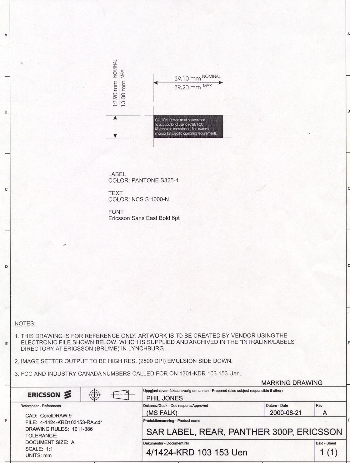
COMPANY NAME: COM NET ERICSSON. EUT: UHF-M SPLIT 450-488 MH Z PANTHER 300P W ORK ORDER NUMBER: 2000278 FCC ID: OWDTR-0003-A Page 41 of 61 APPENDIX B LABEL INFORMATION COMPANY NAME: COM NET ERICSSON. EUT: UHF-M SPLIT 450-488 MH Z PANTHER 300P W ORK ORDER NUMBER: 2000278 FCC ID: OWDTR-0003-A Page 42 of 61 B1: W ARNING LABEL Dimensions (L): 39.20 mm MAX, 39.1 mm NOMINAL (W): 13.00 mm MAX, 12.9 mm NOMINAL B2: FCC ID L ABEL Dimensions (L): 39.20 mm MAX, 39.1 mm NOMINAL (W): 16.00 mm MAX, 15.9 mm NOMINAL B3: LOCATION OF LABEL ON EUT CAUTION: Device must be restricted to occupational use to satisfy FCC RF exposure compliance. See owner’s manual for specific operating requirements. Com-Net Ericsson Serial Number KRD 103 153/x Rxx CANADA: TR-xxx 3636xxx FCC ID: OWDTR-0003-A Label will be placed where battery pak is installed on the device.
Internal Photos
COMPANY NAME: COM NET ERICSSON. EUT: UHF-M SPLIT 450-488 MH Z PANTHER 300P W ORK ORDER NUMBER: 2000278 FCC ID: OWDTR-0003-A Page 50 of 61 APPENDIX F INTERNAL PHOTOGRAPHS COMPANY NAME: COM NET ERICSSON. EUT: UHF-M SPLIT 450-488 MH Z PANTHER 300P W ORK ORDER NUMBER: 2000278 FCC ID: OWDTR-0003-A Page 51 of 61 COMPANY NAME: COM NET ERICSSON. EUT: UHF-M SPLIT 450-488 MH Z PANTHER 300P W ORK ORDER NUMBER: 2000278 FCC ID: OWDTR-0003-A Page 52 of 61 COMPANY NAME: COM NET ERICSSON. EUT: UHF-M SPLIT 450-488 MH Z PANTHER 300P W ORK ORDER NUMBER: 2000278 FCC ID: OWDTR-0003-A Page 53 of 61 COMPANY NAME: COM NET ERICSSON. EUT: UHF-M SPLIT 450-488 MH Z PANTHER 300P W ORK ORDER NUMBER: 2000278 FCC ID: OWDTR-0003-A Page 54 of 61 COMPANY NAME: COM NET ERICSSON. EUT: UHF-M SPLIT 450-488 MH Z PANTHER 300P W ORK ORDER NUMBER: 2000278 FCC ID: OWDTR-0003-A Page 55 of 61 COMPANY NAME: COM NET ERICSSON. EUT: UHF-M SPLIT 450-488 MH Z PANTHER 300P W ORK ORDER NUMBER: 2000278 FCC ID: OWDTR-0003-A Page 56 of 61
RF Exposure Info
Certification Report on Specific Absorption Rate (SAR) Experimental Analysis in Front of Face Com-Net Ericsson Critical Radio Systems Panther 300P Test Date: 22 June, 2000 51 Spectrum Way Nepean ON K2R 1E6 Tel: (613) 820-2730 Fax: (613) 820-4161 email: [email protected] This report shall not be reproduced, except in full, without the express written permission of APREL Laboratories CNEB-PANTHER 300P-3471 Page 1 of 23Project #: CNEB-PANTHER 300P-3471 51 Spectrum WayTel. (613) 820-2730 Nepean, Ontario, K2R 1E6Fax (613) 820 4161 e-mail: [email protected] © APREL 2000 This report shall not be reproduced, except in full,without the express written approval of APREL Laboratories. CERTIFICATION REPORT Subject:Specific Absorption Rate (SAR) Experimental Analysis in Front of Face Product:FM Portable Radio Model:Panther 300P Client:Com-Net Ericsson Critical Radio Systems Address:3315 Old Forest Road Lynchburg, VA 24501 U.S.A. Project #:CNEB-PANTHER 300P-3471 Prepared by:APREL Laboratories 51 Spectrum Way Nepean, Ontario K2R 1E6 Tested by___________________________Date: ________________ Dr. Paul G. Cardinal Director, Laboratories Submitted by____________________________Date: _________________ Dr. Paul G. Cardinal Director, Laboratories Approved by_____________________________Date: _________________ Dr. Jacek J. Wojcik, P. Eng. Page 2 of 23Project #: CNEB-PANTHER 300P-3471 51 Spectrum WayTel. (613) 820-2730 Nepean, Ontario, K2R 1E6Fax (613) 820 4161 e-mail: [email protected] © APREL 2000 This report shall not be reproduced, except in full,without the express written approval of APREL Laboratories. FCC ID:OWDTR0003-A Applicant:Com-Net Ericsson Critical Radio Systems Equipment:FM Portable Radio Model:Panther 300P Standard:FCC 96 –326, Guidelines for Evaluating the Environmental Effects of Radio- Frequency Radiation ENGINEERING SUMMARY This report contains the results of the engineering evaluation performed on a Com-Net Ericsson model Panther 300P FM Portable Radio used in front of the face. The measurements were carried out in accordance with FCC 96-326. The FM Portable Radio was evaluated at its nominal high power level (4 W, 36 dBm) with 100% duty factor. The FM Portable Radio was tested at low, middle and high frequencies (450.025 MHz, 469.975 MHz and 487.975 MHz, respectively), with the three types of antennas offered: ¼ wavelength whip (450-512 MHz) and two helical stub antennas (440-470 MHz and 470-512 MHz), while held in front of a face phantom. The maximum SAR was found to coincide with the peak performance RF output power of the high channel (487.975 MHz) when using antenna I. Test data and graphs are presented in this report. Based on the test results and on how the device will be used, it is certified that the product meets the requirements as set forth in the above specifications, for an occupational / controlled RF exposure environment for partial body exposure. The results presented in this report relate only to the sample tested. Page 3 of 23Project #: CNEB-PANTHER 300P-3471 51 Spectrum WayTel. (613) 820-2730 Nepean, Ontario, K2R 1E6Fax (613) 820 4161 e-mail: [email protected] © APREL 2000 This report shall not be reproduced, except in full,without the express written approval of APREL Laboratories. TABLE OF CONTENTS 1.Introduction.......................................................................................................................4 2.Applicable Documents......................................................................................................4 3.Equipment Under Test......................................................................................................4 4.Test Equipment.................................................................................................................5 5.Test Methodology.............................................................................................................5 6.Test Results.......................................................................................................................6 6.1.Transmitter Characteristics.......................................................................................6 7.SAR Measurements..........................................................................................................7 8.Conclusions.....................................................................................................................11 Appendix A. Measurements Setup and SAR graphs..............................................................12 Appendix B. Manufacturer’s Antenna and Speaker Specifications........................................18 Appendix C. Uncertainty Budget............................................................................................19 Appendix D. Simulated Brain Tissue Material And Calibration Technique..........................20 Appendix E. Validation Scans – On a Head Simulation Phantom.........................................23 Page 4 of 23Project #: CNEB-PANTHER 300P-3471 51 Spectrum WayTel. (613) 820-2730 Nepean, Ontario, K2R 1E6Fax (613) 820 4161 e-mail: [email protected] © APREL 2000 This report shall not be reproduced, except in full,without the express written approval of APREL Laboratories. 1. INTRODUCTION Tests were conducted to determine the Specific Absorption Rate (SAR) of a sample of a Com-Net Ericsson model Panther 300P FM Portable Radio. These tests were conducted at APREL Laboratories’ facility located at 51 Spectrum Way, Nepean, Ontario, Canada. A view of the SAR measurement setup can be seen in Appendix A Figure 1. This report describes the results obtained. 2. APPLICABLE DOCUMENTS The following documents are applicable to the work performed: 1) FCC 96-326, Guidelines for Evaluating the Environmental Effects of Radio- Frequency Radiation 2) ANSI/IEEE C95.1-1992, IEEE Standard for Safety Levels with Respect to Human Exposure to Radio Frequency Electromagnetic Fields, 3 kHz to 300 GHz. 3) ANSI/IEEE C95.3-1992, IEEE Recommended Pr…
Text truncated - open the document above for the full version.
RF Exposure Info
Certification Report on Specific Absorption Rate (SAR) Experimental Analysis on Body Com-Net Ericsson Critical Radio Systems Panther 300P Test Date: 23 June, 2000 51 Spectrum Way Nepean ON K2R 1E6 Tel: (613) 820-2730 Fax: (613) 820-4161 email: [email protected] This report shall not be reproduced, except in full, without the express written permission of APREL Laboratories CNEB-PANTHER 300P-3472 Page 1 of 21Project #: CNEB-PANTHER 300P-3472 51 Spectrum WayTel. (613) 820-2730 Nepean, Ontario, K2R 1E6Fax (613) 820 4161 e-mail: [email protected] © APREL 2000 This report shall not be reproduced, except in full,without the express written approval of APREL Laboratories. CERTIFICATION REPORT Subject:Specific Absorption Rate (SAR) Experimental Analysis on Body Product:FM Portable Radio Model:Panther 300P Client:Com-Net Ericsson Critical Radio Systems Address:3315 Old Forest Road Lynchburg, VA 24501 U.S.A. Project #:CNEB-PANTHER 300P-3472 Prepared by:APREL Laboratories 51 Spectrum Way Nepean, Ontario K2R 1E6 Tested by___________________________Date: ________________ Delia M. Zapata, BSEE Submitted by____________________________Date: _________________ Dr. Paul G. Cardinal Director, Laboratories Approved by_____________________________Date: _________________ Dr. Jacek J. Wojcik, P. Eng. Page 2 of 21Project #: CNEB-PANTHER 300P-3472 51 Spectrum WayTel. (613) 820-2730 Nepean, Ontario, K2R 1E6Fax (613) 820 4161 e-mail: [email protected] © APREL 2000 This report shall not be reproduced, except in full,without the express written approval of APREL Laborat…
Text truncated - open the document above for the full version.
Contact Information
Applicant
Thomas Camper, Jr.(Regulatory Manager)
Technical Contact
Rhein Tech Laboratories, Inc.Desmond A Fraser
[email protected]703-689-0368
360 Herndon Pkwy · Hernodn, Virginia · United States
Technical Specifications
| # | Rule Parts | Frequency Range | Power Output | Emission | Tolerance |
|---|---|---|---|---|---|
| 4 | 22,74,90,95 | 450 MHz - 488 MHz | 4 W | 16K0F3E | 2.5 ppm |
Other Applications from HARRIS CORPORATION
OWDTR-0170-E
Apr 18, 2024XL-85M, 700/800MHZ Land Mobile Radio
Equipment Class
DTS - Digital Transmission System
OWDTR-0172-E
Oct 02, 2023Two47, Base Station Transceiver (700 MHz Band)
Equipment Class
TNB - Licensed Non-Broadcast Station Transmitter
OWDTR-0167-E
Dec 13, 2022XL-90D 7/8/900 MHz Mobile Based Terminal Device
Equipment Class
PCB - PCS Licensed Transmitter
OWDTR-0164-E
Apr 18, 2021XL-400P, Multi-Band Portable Land Mobile Radio
Equipment Class
TNF - Licensed Non-Broadcast Transmitter Held to Face
OWDTR-0162-E
Mar 10, 2021XL-95P, 7/800MHz Portable Land Mobile Radio
Equipment Class
NII - Unlicensed National Information Infrastructure TX