OWDTR-0019-EVHF 110W Mobile Radio
HARRIS CORPORATION
Click to zoom
Application Details
- Equipment Class
- TNB - Licensed Non-Broadcast Station Transmitter
- Date of Grant
- Dec 09, 2003
- Application Purpose
- Original Equipment
- Date of Application
- Jul 17, 2003
- Equipment Note
- VHF 110W Mobile Radio
- Frequency Range
- 136.00000000 - 174.00000000
- Company
- HARRIS CORPORATION
- Country
- United States
Documents & Files
Document Text
Text extracted from the exhibit documents filed with the FCC. Open a document above to read the original.
Users Manual
Roof Top Mount MOBILE ANTENNA for 132-960 MHz WHERE TO MOUNT THE ANTENNA Center roof top mounting is recommended for best performance on cars, vans or trucks with metal tops. For most center roof top installations, the underside of the mounting surface will be exposed by removing the interior dome light, be sure mounting surface is a single thickness of sheet metal. This antenna may also be mounted on any flat, horizontal, metallic surface. The use of PTFE or similar lubricant on the threaded portions and O-Rings of the antenna, prior to assem- bly, will protect from weather and ease future disassembly FIG. 1 ASP1810MA Allen Wrench Large O-Ring Base Spanner Wrench Adapter Whip Adapter Mount & Cable Small O-Ring Whip Set Screw Mini-UHF (crimp) RG-58/U TNC RG-58/U THIS PACKAGE CONTAINS COMPONENTS FOR THE CONFIGURATIONS SHOWN BELOW. A product of M/A-COM. Inc. www.macom.com page 2127-217-1 9/03 Mounting Surface Toggle Bar FIG. 2 INSTALLATION INSTRUCTIONS 1. Select mounting location. Center punch and drill 3/4” diameter hole (Fig. 2). Use a sheet metal punch or hole saw. Remove any burs from around hole. 2. If the under side of the mount location is accessible, the cable may be routed for the interior. Otherwise the cable must be fed through the hole and routed from the mount location. 3. Route cable to radio location, using care to avoid areas where the cable may become damaged. 4. Screw toggle bar onto stanchion. Apply a small amount of PTFE lubricant in the groove on the under side of the mount adapter. Place the O-Ring in the groove. The O-Ring will remain in place while mount adapter is threaded onto the Stanchion. 5. If the underside of the mounting location is acces- sible, push the stanchion up through hole and have a helper thread the mount adapter on stanchion. Other- wise thread the mount adapter onto the stanchion a few turns. Holding the mount adapter, angle the stanchion into the hole as shown in Fig. 3. Adjust the toggle bar to achieve .550” dimension (Fig. 4). 6. Align centering boss on the under side of the mount adapter in hole and use spanner wrench to tighten mount adapter securely (Fig. 4). Be sure mount does not rotate. Slide O-Ring over mount adapter (Fig. 4). 7. Assemble whip and antenna parts onto mount adapter as shown in (Fig, 1). Tighten all parts se- curely. 8. Attach appropriate connector to end of cable at radio (SEE CONNECTOR ASSEMBLY INSTRUCTIONS) 9. Screw connector onto antenna receptacle of radio to complete installation. 10. Refer to tuning instructions as follows. TUNING: 1. It is recommended that an Antenna Tester be used to verify and tune the antenna across the entire specified frequency band. Connect the Antenna Tester between the transceiver and the antenna. 2. Cut whip length to achieve desired frequency per appropriate cutting chart. Remove sharp burrs. 3. Loosen set screw and bottom whip into whip adapter. Tighten set screw. 4. When tuning is complete, disconnect the Antenna Tester and connect the Transceiver to the antenna. Stanchion Spanner Wrench Adapter Square C/S “O” Ring 3/4” hole Toggle Bar Adapter Adapter Mounting Surface FIG. 4 FIG. 3 Centering Boss page 3 CUTTING CHARTS FIG. 7 (800-960 MHz) Loosen whip adapter from black base and remove whip assembly before entering an automatic car was to prevent damage to antenna. When unscrew- ing whip be sure black base is not loosened. If base should loosen, tighten it against mounting surface using spanner wrench. Frequency (MHz)Whip Length (inches) 12920 1/16 13219 9/16 13519 1/16 13818 13/16 14118 5/16 14418 14717 9/16 15017 1/4 15317 15916 5/16 16215 15/16 16515 9/16 16815 3/8 17115 1/16 17414 7/8 Frequency (MHz)Whip Length (inches) 406-4405 3/16 415-4555 1/16 435-4704 15/16 455-4904 11/16 475-5124 5/16 Frequency (MHz)Whip Length (inches) 800-8552 13/16 855-9202 1/2 920-9602 1/4 FIG. 6 (406-512 MHz) FIG. 5 (129-174 MHz) page 4127-217-1 9/03 TNC CRIMP CONNECTOR INSTRUCTIONS MINI-UHF CRIMP CONNECTOR INSTRUCTIONS
Users Manual
Operator’s Manual MM102341V1 P5A M7100 IP Series Mobile Radios 2 SUPPLEMENTARY INFORMATION: At this time, the M7100 IP mobile radio may not be operated while in a desktop station in the European Community since it does not meet immunity requirements when operated in this mode. The M7100 IP mobile radio can be used in both trunked and conventional applications. ACKNOWLEDGEMENTS This device is made under license under one or more of the following US patents: 4,590,473; 4,636,791; 5,148,482; 5,185,796; 5,271,017; 5,377,229. The voice coding technology embodied in this product is protected by intellectual property rights including patent rights, copyrights, and trade secrets of Digital Voice Systems, Inc. The user of this technology is explicitly prohibited from attempting to decompile, reverse engineer, or disassemble the Object Code, or in any other way convert the Object Code into human-readable form. EDACS is a registered trademark and ProGrammer, SCAT, Failsoft, ProSound, ProScan, Aegis, ProFile, ProVoice, and G-STAR are trademarks of M/A-COM, Inc. NOTICE! This manual covers M/A-COM, Inc. products manufactured and sold by M/A-COM, Inc. NOTICE! Repairs to this equipment should be made only by an authorized service technician or facility designated by the supplier. Any repairs, alterations or substitution of recommended parts made by the user to this equipment not approved by the manufacturer could void the user's authority to operate the equipment in addition to the manufacturer's warranty. This manual is published by M/A-COM, Inc., without any warranty. Improvements and changes to this manual necessitated by typographical errors, inaccuracies of current information, or improvements to programs and/or equipment, may be made by M/A- COM, Inc., at any time and without notice. Such changes will be incorporated into new editions of this manual. No part of this manual may be reproduced or transmitted in any form or by any means, electronic or mechanical, including photocopying and recording, for any purpose, without the express written permission of M/A-COM, Inc. Copyright© 2003 M/A-COM, Inc. All rights reserved. 3 TABLE OF CONTENTS Page RF ENERGY EXPOSURE INFORMATION .............................................5 RF ENERGY AWARENESS, CONTROL, AND OPERATION ................5 COMPLIANCE WITH RF EXPOSURE STANDARDS ............................6 OPERATION SAFETY RECOMMENDATIONS.......................................8 TRANSMITTER HAZARDS....................................................................8 SAFE DRIVING RECOMMENDATIONS ................................................9 OPERATING RULES AND REGULATIONS .........................................10 OPERATING TIPS................................................................................11 INTRODUCTION....................................................................................12 USER INTERFACE ................................................................................13 CONTROLS ...........................................................................................15 POWER ON-OFF VOLUME KNOB ......................................................15 SYSTEM/GROUP CHANNEL KNOB....................................................15 RAMP CONTROL .................................................................................15 SCAN ON/OFF .....................................................................................15 SCAN ADD/DELETE ............................................................................16 INDICATORS........................................................................................16 KEYPAD ...............................................................................................17 DISPLAY................................................................................................21 RADIO STATUS ICONS .......................................................................21 MESSAGES..........................................................................................22 ALERT TONES ......................................................................................27 CALL ORIGINATE ................................................................................27 AUTOKEY (TRUNKED MODE ONLY)..................................................27 CALL QUEUED (TRUNKED MODE ONLY) .........................................27 SYSTEM BUSY (TRUNKED MODE ONLY) .........................................27 CALL DENIED (TRUNKED MODE ONLY) ...........................................27 CARRIER CONTROL TIMER ...............................................................27 KEY PRESS ALERT .............................................................................28 DUAL CONTROL SWITCHING ............................................................28 OPERATION ..........................................................................................29 TURNING THE RADIO ON...................................................................29 SELECTION MODE RULES .................................................................29 DIRECT ACCESS.................................................................................30 MENU ...................................................................................................31 FEATURE ENCRYPTION DISPLAY.....................................................35 SYSTEM/GROUP/CHANNEL SELECTION..........................................37 TRUNKED MODE OPERATION............................................................39 RECEIVING A CALL.............................................................................39 SENDING A CALL................................................................................39 CONVENTIONAL FAILSOFT ...............................................................40 EMERGENCY OPERATION.................................................................40 SYSTEM SCAN OPERATION ..................................................…
Text truncated - open the document above for the full version.
Users Manual
Installation Manual MM102342V1 P5A M7100 IP Series Mobile Radio 2 SUPPLEMENTARY INFORMATION: At this time, the M7100 IP mobile radio may not be operated while in a desktop station in the European Community since it does not meet immunity requirements when operated in this mode. The M7100 IP mobile radio can be used in both trunked and conventional applications. ACKNOWLEDGEMENTS This device is made under license under one or more of the following US patents: 4,590,473; 4,636,791; 5,148,482; 5,185,796; 5,271,017; 5,377,229. The voice coding technology embodied in this product is protected by intellectual property rights including patent rights, copyrights, and trade secrets of Digital Voice Systems, Inc. The user of this technology is explicitly prohibited from attempting to decompile, reverse engineer, or disassemble the Object Code, or in any other way convert the Object Code into human-readable form. EDACS is a registered trademark and ProGrammer, SCAT, Failsoft, ProSound, ProScan, Aegis, ProFile, ProVoice, and G-STAR are trademarks of M/A-COM, Inc. Torx is a registered trademark of CAMCAR Division TEXTRON, Inc. POZIDRIV is a registered trademark of Phillips International Company. NOTICE! This manual covers M/A-COM, Inc. products manufactured and sold by M/A-COM, Inc. NOTICE! Repairs to this equipment should be made only by an authorized service technician or facility designated by the supplier. Any repairs, alterations or substitution of recommended parts made by the user to this equipment not approved by the manufacturer could void the user's authority to operate the equipment in addition to the manufacturer's warranty. This manual is published by M/A-COM, Inc., without any warranty. Improvements and changes to this manual necessitated by typographical errors, inaccuracies of current information, or improvements to programs and/or equipment, may be made by M/A-COM, Inc., at any time and without notice. Such changes will be incorporated into new editions of this manual. No part of this manual may be reproduced or transmitted in any form or by any means, electronic or mechanical, including photocopying and recording, for any purpose, without the express written permission of M/A-COM, Inc. Copyright© 2003 M/A-COM, Inc. All rights reserved. 3 TABLE OF CONTENTS Page TABLE OF CONTENTS ....................................................................... 3 SAFETY INFORMATION ..................................................................... 4 RF ENERGY EXPOSURE INFORMATION.......................................... 5 RF ENERGY AWARENESS, CONTROL, AND OPERATION ......... 5 COMPLIANCE WITH RF EXPOSURE STANDARDS...................... 6 OPERATION SAFETY RECOMMENDATIONS ................................... 8 TRANSMITTER HAZARDS.............................................................. 8 SAFE DRIVING RECOMMENDATIONS.......................................... 9 OPERATING RULES AND REGULATIONS...................................... 10 OPERATING TIPS ......................................................................... 11 INTRODUCTION ................................................................................ 12 UNPACKING AND CHECKING EQUIPMENT ................................... 13 PLANNING THE INSTALLATION...................................................... 17 EQUIPMENT REQUIRED .................................................................. 19 INSTALLATION ................................................................................. 20 RUNNING CABLES....................................................................... 20 CONTROL UNIT MOUNTING........................................................ 28 PIGTAIL BRACKET....................................................................... 28 SPEAKER ......................................................................................31 MICROPHONE HANGER AND/OR HOOKSWITCH MOUNTING . 32 SIREN AND LIGHT ........................................................................ 32 RADIO MOUNTING AND FINAL HOOK-UP .................................. 33 DUAL CONTROL UNITS ................................................................... 37 PRE-INSTALLATION PROGRAMMING PROCEDURE WITH PROGRAMMER - FRONT MOUNT ..........................................38 PRE-INSTALLATION PROGRAMMING PROCEDURE WITH PROGRAMMER - REMOTE MOUNT ....................................... 40 INSTALLATION INSTRUCTIONS FOR FRONT MOUNT DUAL CONTROL UNITS..................................................................... 42 INSTALLATION INSTRUCTIONS FOR REMOTE MOUNT DUAL CONTROL UNITS..................................................................... 45 FIELD PROGRAMMING WITH PROGRAMMER – DUAL CONTROL UNITS..................................................................... 48 DUAL RADIO UNITS ......................................................................... 54 PRE-INSTALLATION PROGRAMMING PROCEDURE WITH PROGRAMMER – DUAL RADIO UNITS................................... 54 PROGRAMMING WITH PC PROGRAMMER – DUAL RADIO UNITS........................................................................................ 58 ANTENNA...................................................................................... 63 WARRANTY....................................................................................... 64 4 SAFETY INFORMATION The operator of any mobile radio should be aware of certain hazards common to the operation of vehicular radio transmissions. A list of several possible hazards is given: 1. Explosive Atmospheres - Just as it is dangerous to fuel a vehicle with the motor running, similar hazards exist when operating a mobile radio, be sure to turn the radio off while fueling the vehicle. Do not carry containers of fuel in the trunk of the vehicle if the radio is mounted in the trunk. 2. Interference to Vehicular Electronics Systems - Electronic fuel injection systems, electronic anti-skid braking systems, electronic cruise control systems, etc., are t…
Text truncated - open the document above for the full version.
Block Diagram
Rhein Tech Laboratories Client: M/A COM, Inc. 360 Herndon Parkway Model: M7100 (IP) VHF Mobile Radio Suite 1400 Standards: FCC Part 90/IC RSS-119 Herndon, VA 20170 Report Number: 2003067 http://www.rheintech.com Date: May 8, 2003 47 of 62 APPENDIX F: BLOCK DIAGRAM Please refer to the following pages. AD Function 1: RX Demodulation FM(Voice),C4FM, IMBE,AMPF,AEGIS CQPSKFunction 2: 2'nd IF Filter Band widthFunction 3: Noise Squelch, Signaling squelchFunction 4: CG DECODE CTCSS, CDCSS, STEFunction 5: Signaling DECODE GE-STAR,DTMF,EDACS PREAMP+ RSSI/REFDET DA1 Controller ASIC (HILLARY) SCK+ SDT+ PLLENB+ PLLFST1-PLLFST2- PLL DATA CONTROL TX POWER CONTRO L EXTRX SEG1SEG2SEG3 VCO SHIFT CONTROL PLL LOCK DETECT VCOENB+ DPTT+ LOOP FIL CONTROL SP AMP Function 1: TX modulaation Signal genarate FM(Voice),C4FM, IMBE,AEGISFunction 2: CG ENCODE CTCSS, CDCSS, STEFunction 3: Signaling ENCODE GE-STAR, DTMF, EDACS 5V REG MIXED SIGNL ASIC (PATTI) CODEC HST/DSP INTERFACE FWDDET Mute RX MUTE DA2, DA3 SWA+ MIC HI FET SW EXT MIC SEG4 RX SAMPLE SERIAL CONTROL 3.3V REG 3.3V for DSP TYPE3 SRAM 128k x 16bit DSPCLK (19.2MHz) DSP FLASH EEPROM 2M x 8bit SRAM 512k x 2 x 8bit S/N ROM EEPROM 2k x 8bit ADDRESS DATA SCL SDA S/N_ROM ORCC/LCC SPKR1/SPKR2 THERM AD 5V for LOGIC 5V REG 5V for ANALOG 1.5V REG 1.5V for DSP SPLTSW- TXENB+ W/N APCREF DPTT+ BPFCONT +5V GND BPF_H/L VOL HI IGN A+ RESET RESET- 1st IF Amp1 1st IF Fil2 RXIF+ (450kHz) 2nd Mixer IF IC SA647DK IF AMP LOGAMP SW BPF Wide BPF Narrow SW BPF IF AMP LOGAMP 1st IF Fil1 IF M7100 VHF A/L & IF UNIT BLOCK DIAGRAM DACMC0003G Feb./07/2003 DSPCLK1 ATT 0dB RX FRONT END CONTROLRX VCO SELECT CTL ON TYPE2TYPE1 9V REG 9V REG 9V for TX 9V for LOGIC 9V for RF 9V for IF SW BPF C4FM 2nd IF AMP C4FMSEL RXIF- (450kHz) FET SW SWA+2 for SP AMP POWER CONTROL POWER_SENSE POWER_LATCH REFDET RSSI VC-TCXO 19.2MHz 1st IF Amp2 5V REG TYPE3 TX CONTROL A+ I2-C bus PLLENB2+ 19.2MHz Loop Fil G f VCO 45.55MHz or 44.65MHz +9VA +9VD +9VRx +9VI Serial Port 1 PLLLOCK+ LOCKDET Serial Port 2 SDATA SONOFF HORNRING HKSW XDATAIN XDATAOUT CTS OUT2 IGN SEN FPROG RTS INP1 OUT1 INP2 RS485RS232 RS485+ RS485- RQST CUTST DE MD0 RESET_CH C/H Interface New C/H Interface PC Interface External Interface EEPROM FIPS-140 12bit D/A CS-SCLKDIN DOUTA DOUTB LPF RXDSP_INT SI SO SCK CS HD0 PLLLOCK2+ 5V for IF VCOENB+ DPTT+ INT0 MOD-AF Amp ADDER ( Direct Mod )( to VCTCXO ) MOD-AF AFC MOD MOD/AFC MOD/AFC ADDER AFC +5VD From CPLD DATA CLKR FSR BPF C4FM AMP 14bit ADC CPLD Differential AMP 96kHz DATA CLKR FSR To DSP RXSIF_DSPSYNCRXSIF_DSPCLKRXSIF_DSPDATA C4FMSEL SW SW SW 2nd IF AMP BPF C4FM FM_ADC+ PLLFST2- +1.5V+3.3V +5VD+5VA +5VI FIPS-140 OTP ROM 512k x 2 x 8bit ADDRESS A0 - A15 DATA D0 - D15 DS IS BDR2 BCLKR2 BFSR2 4k x 8bit SW IF SECTION PD 1/2 9.6MHz LPF POTENTIOMETER CH 1CH 0 D R ATT LPF R/T SW Power Detector Power Combin AMP A-Class AMP A-Class ATT AMP OSC for RXL OSC for TXL TankTank AMP BPF BPF APC AMP 1st Mix Loop Filter SW PLL IC PLLLOCK+ SCK+ SDT+ PLLENB+ PLLFST2- PLLFST1- SEG1 SEG2 SEG3 AMP ATT AMP ATT 0dB APCREF A+ +9VA FWDDET SWA+ SEG2SEG1SEG3 SCK+ SDT+ PLLENB+ PLLFST1- PLLFST2- PREAMP+ SPLTSW- SEG4 TXENB+ ATT 0dB IF AMP DPTT+ MOD PLLLOCK+ AMP A-Class TXENB+ TXENB+ TXENB+ TXENB+ ATT DPTT+ AMP 9.6M 9.6M TYPE1 LPF THERM +9V+5V DPTT+ DPTT- DPTT+ REFDET Thermal Detect ATT LPF AMP OSC for RXH Tank OSC for TXH Tank AMP BPF ATT PREAMP+ SPLTSWL+ LPF ATT SPLTSWL+ +3.3V LPF +3V SYN +9V SYN +8 VA +5V SYN SPLTSWL+ SPLTSWL+ DPTT- DPTT- DPTT+ DPTT- BPFCONT BPFCONT BPFCONT BPFCONT AMP AB- Class AMP AB- Class AMP AB- Class doble PA Module AMP AB- Class AMP AB- Class AMP AB- Class doble PA Module SPLTSW- DPTT- SPLTSW- SPLTSW- MOD M7100 VHF TRX/SYNTHESIZER UNIT BLOCK DIAGRAM DACMN0003F Feb./07/2003 TYPE2 +9VRX COM Vref 15 101520 2125303540 1 5 101520 21 25303540 1 1 20 19 5 1015 253037 1 21 5 101520 25303540 45.1MHz 45.1MHz IF IF A+ GND +A GND 1 5 1015 20 2530354021 1. SUPGND2. XDATAIN3. XDATAOUT4. RS485+5. RS485-6. CTS7. N/C8. FPROG9. OUT210.IGNSEN11.MICHI12.ALO13.VOLHI14.CTL ON15.XTONENC16.XTONEDEC17.RQST18.N/C19.N/C20.N/C 21.RTS22.INP123.OUT124.INP225.IGN A+26.N/C27.HKSW28.EXTMIC29.EXTRX30.FDISC31.EXTARO32.CUTST33.N/C34.N/C35.N/C36.SDATA37.SONOFF38.HORNRING39.N/C40.N/C 1. SUPGND2. XDATAIN3. XDATAOUT4. RS485+5. RS485-6. CTS7. GND8. FPROG9. OUT210.IGNSEN11.MICHI12.ALO13.VOLHI14.CTLON15.XTONENC16.XTONEDEC17.RQST18.SPKR119.SPKR2 20.RTS21.INP122.OUT123.INP224.IGN A+25.SWA+26.HKSW27.EXTMIC28.EXTRX29.FDISC30.EXTARO31.CUTST32.N/C33.N/C34.N/C35.SDATA36.SONOFF37.HORNRING 1.SWA+2.GND3.SPKR14.SPKR2 1. MICHI2. MICLO3. SWA+4. SWA+5. SPKR16. SPKR17. SPKR28. SPKR29. CTLON10.GND11.GND12.RS485+13.RS485+14.RQST15.CUTST16.SDATA17.SONOFF18.HORNRING19.HKSW20.N/C 21.XDATAIN22.XDAT AOUT 23.FPROG24.RESET_CH25.MD026.N/C27.N/C28.N/C29.N/C30.N/C31.N/C32.N/C33.N/C34.N/C35.N/C36.N/C37.N/C38.N/C39.N/C40.N/C TM-0298LH TRX/SYNTHESIZER UNIT TC-0135V A/L & IF UNIT ORCC Rear Connector (37pin D-sub) Power supply connector Antenna connector (TNC) 9.6MHz 9.6MHz 1. A+2. A+3. A+4. A+5. REFDET6. GND7. FWDDET8. +9VA9. TXENB+10.THREM11.APCREF12.GND13.SDT14.PLLENB15.SCK16.PLLLOCK17.GND18.not use19.GND20.not use 21.BPFCONT22.+9VRX23.PREAMP+24.GND25.SPLTSW26.SWA+27.N/C28.GND29.DPTT+30.SEG131.SEG232.SEG333.SEG434.PLLST135.PLLST236.GND37.MOD38.GND39.TYPE240.TYPE1 21.BPFCONT22.+9VRX23.PREAMP+24.GND25.SPLTSW26.SWA+27.N/C28.GND29.DPTT+30.SEG131.SEG232.SEG333.SEG434.PLLST135.PLLST236.GND37.MOD38.GND39.TYPE240.TYPE1 1. A+2. A+3. A+4. A+5. REFDET6. GND7. FWDDET8. +9VA9. TXENB+10.THREM11.APCREF12.GND13.SDT14.PLLENB15.SCK16.PLLLOCK17.GND18.not use19.GND20.not use 1 5 1015 20 2530354021 DZA-117LHS Frame UNIT J2U-PJ-0016 W3 U-PK-3063A W4 XK6W-2EE1-040 W5 XK6W-2EE1-040 W1 U-PK-3062 J1CCT9402-0502R W2U-PK-3050 C1,C2DF553F102P50 UJRC From: TQ-0066 CONNECT UNIT M7100 VHF SYNTHETIC BLOCK DIAGRAM DAJHM0002F Feb./07/2003 J1001 J711 J703 J704 J701 J1301J712 J201 J501
Cover Letter(s)
M/A-COM, Inc. 221 Jefferson Ridge Parkway Lynchburg, VA 24501 Telephone: 434.455.9527 www.macom.com September 16, 2003 Mr. Tim Harrington Federal Communications Commission FCC Laboratory Division Equipment Authorization Branch 7435 Oakland Mills Road Columbia Maryland 21046 Mr. Harrington, With regard to your email of August 22, 2003 concerning FCC ID OWDTR-0019-E, an MPE report, and the User and the Installation manuals have been submitted through the web site for your review. I trust this will address the seven points identified in your email. If I can be of further help please contact me. Sincerely, Daryl Popowitch Engineering Project Manager M/A-COM, Inc. – Lynchburg, VA
Cover Letter(s)
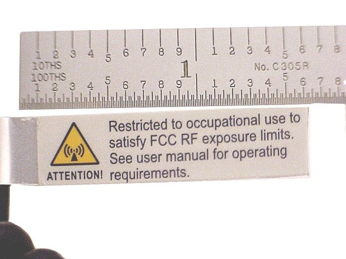
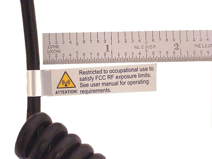
M/A-COM, Inc. 221 Jefferson Ridge Parkway Lynchburg, VA 24501 Telephone: 434.455.9527 www.macom.com October 20, 2003 Mr. Andy Leimer Federal Communications Commission FCC Laboratory Division Equipment Authorization Branch 7435 Oakland Mills Road Columbia Maryland 21046 Mr. Leimer, With regard to your email of September 23, 2003 concerning FCC ID OWDTR-0019-E, under 731 confirmation number EA696957, I am providing explanatory discussion to each of the items you presented. Each numbered item is reproduced in this letter for continuity. 1) Please clarify nominal conducted output power rating for this device, and power per 90.205(q). Form 731 line item should list nominal power. The Test Report says 150.6 Watts and the form 731 line item says 50 Watts. Response : The power discrepancy was a keyboarding data entry error. The correct conducted output power rating is 51.48 dBm, as reflected in the revised Test Report uploaded to the FCC web site. Additionally, M/A-COM, Inc. does not believe that 90.205(q) applies in this case. M/A-COM, Inc. is filing for an equipment authorization, not for a license of system operation. 2) Due to the higher power and low MPE limit (0.2 mW/cm^2) in human body resonance freq. range, additional information is needed to assure RF exposure compliance. MPE estimation establishes a larger bystander compliance distance than can be maintained just based on sizes of most vehicles. An MPE test report for typical installation configuration may be useful, including field data vs. horizontal distance. Response : MPE estimations have been filed in the report previously loaded to the website. Although a test report showing results of field intensity vs. horizontal distance from the active element may provide interesting data with regard to today’s vehicle body styling, M/A-COM, Inc. believes that EM wave radiation from the quarter wave element, located in the center of the vehicle, will not be materially changed as a result of a new radio model. Microphones are tagged with warning labels directing the user to use information in the User and Installation manuals. With the corrected reports submitted to the FCC website, the exposure distances have been reduced as well as the power levels. M/A-COM, Inc. 221 Jefferson Ridge Parkway Lynchburg, VA 24501 Telephone: 434.455.9527 www.macom.com An error in the previously filed MPE report has been corrected, resulting in a somewhat shortened MPE distance for both uncontrolled and controlled cases. The updated MPE report has been loaded to the FCC website. 3) Related to 2), please clarify distance for gen. pub. MPE compliance, and provide more details of how it can be ensured that operator will limit transmissions when persons are close to vehicle. MPE estimate done at 116 W - EMC report pg 9/62 shows 141 W, SAR report has 144.5 W which gives bystander minimum MPE compliance distance of approx. 3.07m with 3dBd=5.15dBi antenna. Response : The distances for general public and occupational, are detailed in both the User and Installation manuals. Operator transmission limiting is provided through operator training by the user’s Communication Officer or other responsible party. Additionally, microphone labeling is incorporated directing the user to use information contained in the manual(s). Within the manual are user available websites and M/A-COM telephone numbers where additional assistance may be obtained. These manual’s, which follow the content driven scope of TIA TELECOMMUNICATIONS SYSTEMS BULLETIN, PRIVATE LAND MOBILE RADIO (FCC PART 90) TWO WAY MOBILE AND PORTABLE EQUIPMENT RF EXPOSURE (EME) LABELING, PRODUCT MANUAL, USER AWARENESS, AND CONTROL INFORMATION TO MEET FCC MPE/SAR GUIDELINES, TSB 133 June 2003, have been loaded to the FCC website, and are available for your review. 4) Please submit occupational label and label installation exhibit, e.g., with label on microphone cord. Response : The FCC website has been loaded with jpg files showing the installation exhibits requested. It is the product warning label format as recommenced in TIA TELECOMMUNICATIONS SYSTEMS BULLETIN, PRIVATE LAND MOBILE RADIO (FCC PART 90) TWO WAY MOBILE AND PORTABLE EQUIPMENT RF EXPOSURE (EME) LABELING, PRODUCT MANUAL, USER AWARENESS, AND CONTROL INFORMATION TO MEET FCC MPE/SAR GUIDELINES, TSB 133, June 2003. The installation exhibits show three microphones and a hand controller. There is a standard microphone, a noise cancelling microphone, and a DTMF microphone. The handheld controller is also shown. There is no artwork drawing supplied, as the format is from the described source above; our microphone supplier installs the product warning label. 5) SAR report is not relevant for this filing. Please inform if you wish to withdraw the exhibit. Response : Although the SAR report is not required, M/A-COM, Inc. believes SAR provides the best estimation of exposure distances, as addressed in NPRM FCC03-132, Subsection H, paragraph 44. We believe it is relevant and wish to have it remain part of this equipment authorization filing. 6) Please revise user manual to include more description of occupational vs. general limits and personnel to which these apply. M/A-COM, Inc. 221 Jefferson Ridge Parkway Lynchburg, VA 24501 Telephone: 434.455.9527 www.macom.com Response: FCC website has been uploaded with User and Installation manuals which reflect the content of TIA TELECOMMUNICATIONS SYSTEMS BULLETIN, PRIVATE LAND MOBILE RADIO (FCC PART 90) TWO WAY MOBILE AND PORTABLE EQUIPMENT RF EXPOSURE (EME) LABELING, PRODUCT MANUAL, USER AWARENESS, AND CONTROL INFORMATION TO MEET FCC MPE/SAR GUIDELINES TSB 133, June 2003. A two-category table is included, with user direction on the meaning and information on how to obtain more information and instruction if desired. 7) Please describe "authorized" antennas referenced in users manual, including length, gain, model #s, etc. It is preferred to use only 0dBd or lower gain. Response: The User and Installation manuals reference the M…
Text truncated - open the document above for the full version.
Cover Letter(s)
M/A-COM, Inc. 221 Jefferson Ridge Parkway Lynchburg, VA 24501 Telephone: 434.455.9527 www.macom.com November 13, 2003 Mr. Andy Leimer Federal Communications Commission FCC Laboratory Division Equipment Authorization Branch 7435 Oakland Mills Road Columbia Maryland 21046 Mr. Leimer, With regard to your email of October 31, 2003 (correspondence 25894) concerning FCC ID OWDTR- 0019-E, under 731 confirmation number EA696957, I am providing explanatory discussion to each of the items you presented. Each numbered item is reproduced in this letter for continuity. 1) Please submit close-up photos and/or drawings of RF exposure info label. Include photo/drawing of RF exposure label for console if applicable. Response: JPG files of close-up photos have been loaded to the website. Console is not applicable. 2) Reply to crn 25753 indicates "conducted output power" is 51.48 dBm = 141 W. For RF exposure evaluation with 50% usage duty factor this is 70.5 W. MPE estimation uses 48.6 dBm = 72.5 W. 90.205(q) is relevant at equipment authorization time for purposes of RF exposure evaluation and establishing installation and use instructions, which should account for maximum expected device output. Form731 should list nominal output, but RF exposure should account for 90.205(q) allowed power. Per 90.205(q) if 141 W is authorized "rated output power," operation to 169 W is allowed. Please clarify device output power, and revise RF exposure evaluation and installation and…
Text truncated - open the document above for the full version.
Contact Information
Applicant
Thomas Camper, Jr.(Regulatory Manager)
Technical Contact
M/A-Com, Inc.Daryl Popowitch
[email protected]434-455-9527
221 Jefferson Ridge Parkway · Lynchburg, Virginia · United States
Non-Technical Contact
M/A-Com, Inc.Daryl Popowitch
[email protected]434-455-9527
Test Firm
Rhein Tech Laboratories, Inc.Rick McMurray
Technical Specifications
| # | Rule Parts | Frequency Range | Power Output | Emission | Tolerance |
|---|---|---|---|---|---|
| 8 | 22,80,9 | 136 MHz - 174 MHz | 109.9 W | 7K8F1E | 5 ppm |
Other Applications from HARRIS CORPORATION
OWDTR-0170-E
Apr 18, 2024XL-85M, 700/800MHZ Land Mobile Radio
Equipment Class
DTS - Digital Transmission System
OWDTR-0172-E
Oct 02, 2023Two47, Base Station Transceiver (700 MHz Band)
Equipment Class
TNB - Licensed Non-Broadcast Station Transmitter
OWDTR-0167-E
Dec 13, 2022XL-90D 7/8/900 MHz Mobile Based Terminal Device
Equipment Class
PCB - PCS Licensed Transmitter
OWDTR-0164-E
Apr 18, 2021XL-400P, Multi-Band Portable Land Mobile Radio
Equipment Class
TNF - Licensed Non-Broadcast Transmitter Held to Face
OWDTR-0162-E
Mar 10, 2021XL-95P, 7/800MHz Portable Land Mobile Radio
Equipment Class
NII - Unlicensed National Information Infrastructure TX