OWDTR0001-EEDACS-300P
HARRIS CORPORATION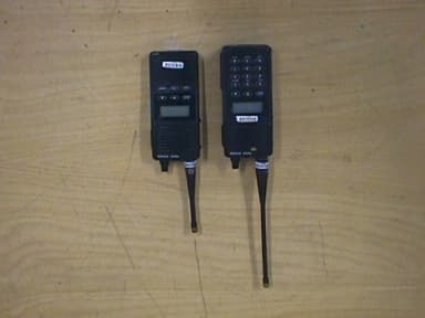
Click to zoom
Application Details
- Equipment Class
- TNT - Licensed Non-Broadcast Transmitter Worn on Body
- Date of Grant
- Aug 01, 2000
- Application Purpose
- Original Equipment
- Date of Application
- Feb 14, 2000
- Equipment Note
- EDACS-300P
- Frequency Range
- 851.00000000 - 869.00000000
- Company
- HARRIS CORPORATION
- Country
- United States
Documents & Files
Document Text
Text extracted from the exhibit documents filed with the FCC. Open a document above to read the original.
Users Manual
EN/LZT 123 5652/1 R1A Operator’s Manual EDACS 300P System/Scan Portable Radio 2 Table of Contents User Interface..............................................................................3 Basic Operation..........................................................................6 Trunked Mode Operation............................................................8 Conventional Operation...........................................................13 Programmable Alert Tones......................................................14 Error Messages.........................................................................15 Changing the Battery Pack.......................................................16 Operating Rules and Regulations............................................18 Intrinsically Safe Usage............................................................19 Operating Tips..........................................................................20 The software contained in this device is copyrighted by Com-Net Ericsson. Unpublished rights are reserved under the copyright laws of the United States. NOTICE! This manual is published by Com-Net Ericsson, without any warranty. Improvements and changes to this manual necessitated by typographical errors, inaccuracies of current information, or improvements to programs and/or equipment, may be made by Com-Net Ericsson, at any time and without notice. Such changes will be incorporated into new editions of this manual. No part of this manual may be reproduced or transmitted in any form or by any means, electronic or mechanical, including photocopying and recording, for any purpose, without the express written permission of Com-Net Ericsson. Copyright © 2000 Com-Net Ericsson. All rights reserved. 3 User Interface This manual describes the basic functions and operation of the EDACS 300P System/Scan portable radio. For more detailed information about the features and operation, refer to the appropriate EDACS 300P Maintenance Manual or contact your System Administrator. EMERGENCY/ HOME BUTTON POWER ON/OFF VOLUME KNOB ANTENNA Figure 1. EDACS 300P Top View 4 CLEAR/ MONITOR/ SHIFT LOCK ON/OFF SCAN ON/OFF RECALL DISPLAY STORE SPECIAL CALLS SELECT SYSTEM/ GROUP/ CHANNEL PTT BUTTON ON/OFF/ VOLUME ANTENNA Figure 2. EDACS 300P System Model 5 CLEAR/ MONITOR/ SHIFT SCAN ON/OFF DISPLAY SPECIAL CALLS SELECT SYSTEM/ GROUP/ CHANNEL PTT BUTTON ON/OFF/ VOLUME ANTENNA Figure 3. EDACS 300P Scan Model 6 Basic Operation Locking/Unlocking Keypad (System Model) 1. Press and hold the C/M key. 2. Press and release the LOCK key. Then release the C/M key. Selecting System 1. Press and release the C/M key. Then use the and keys to select the desired system. 2. The SYS field displays the current System selected. Selecting Group/Channel 1. Press the and keys to access the desired group/channel. Enabling/Disabling Scan 1. Press and release the SCN key to toggle Scan ON/OFF. “SCN” is displayed when Scan is enabled. Modifying Scan List 1. Select desired Group/Channel to be added/deleted. If Group/Channel is currently in Scan list, “S” is displayed. 2. Press and hold the C/M key. 3. Press and release the SCN key. Then release the C/M key. 7 4. If selected Group/Channel was not in Scan list, it will be added. If selected Group/Channel was in Scan list, it will be deleted. Home/Emergency Key Definition Pressing the red Home/Emergency button will perform one of the four operations below, depending upon how the radio was programmed. 1. Radio will switch to the programmed home System and/or Group, and send an emergency transmission. 2. Radio will send an emergency transmission on the current System/Group. 3. Radio will switch to the home System and/or Group. 4. Button is not active. Declaring Emergency 1. Press and hold the red Emergency/Home button (the length of time is programmable; check with the System Administrator). 2. If programmed, an “E” is displayed in the SYS field and/or an alert tone sounds. 3. Press PTT button to transmit your message. 4. Release PTT button when transmission is complete. 8 Trunked Mode Operation Transmitting a Call Group Call 1. Select desired System and Group. 2. Ensure that no one is transmitting on selected Group by observing display for absence of “BSY” indicator. 3. Press and hold PTT button. 4. When “TX” is displayed, speak into microphone. 5. Release PTT button when transmission is complete. Wait for reply. Individual Call 1. Press the SPC key. “S” and “PC” will be displayed. 2. The SYS field displays “SP”. The GRP field displays the last accessed special call number from the pre-programmed list. 3. Scan Model: Press the or keys to scroll through the special call list until the desired number is displayed. System Model: Press the or keys to scroll through the special call list until the desired number is displayed; or Enter the ID number of the radio to be called. (To recall the last individual number entered, press and hold C/M and then press the #/RCL key.) 4. Press and hold PTT button to initiate call. 5. When “TX” is displayed, speak into microphone. 9 6. Release PTT button when transmission is complete. Wait for reply. 7. When call is complete, double click the C/M key to exit Special Call mode. Phone Call 1. Press the SPC key. “S” and “PC” will be displayed. 2. The SYS field displays “SP”. The GRP field displays the last accessed special call number from the pre-programmed list. 3. Scan Model: Press the or keys to scroll through the special call list until the desired number is displayed. System Model: Press the or keys to scroll through the special call list until the desired number is displayed; or Enter the telephone number to be called. Complete the phone number entry by pressing the * key. (To recall the last phone number entered, press and hold C/M and then press the #/RCL key.) 4. Press and release PTT button to initiate call. 5. “BSY” is displayed and DTMF tones are sent. 6. When the receiving party answers the c…
Text truncated - open the document above for the full version.
Users Manual
CLIENT:COM-NET ERICSSON CRITICAL RADIO SYSTEMS, INC. EUT:EDACS-300P CLIENT REFERENCE NUMBER:QRTL00-230 WORK ORDER NUMBER:2000043 FCC ID:OWDTR0001-E Page 108 of 131 APPENDIX H: PRELIMINARY USER’S MANUAL EN/LZT 123 5652/1 R1A Operator’s Manual EDACS 300P System/Scan Portable Radio 2 Table of Contents User Interface..............................................................................3 Basic Operation..........................................................................6 Trunked Mode Operation............................................................8 Conventional Operation...........................................................13 Programmable Alert Tones......................................................14 Error Messages.........................................................................15 Changing the Battery Pack.......................................................16 Operating Rules and Regulations............................................18 Intrinsically Safe Usage............................................................19 Operating Tips..........................................................................20 The software contained in this device is copyrighted by Com-Net Ericsson. Unpublished rights are reserved under the copyright laws of the United States. NOTICE! This manual is published by Com-Net Ericsson, without any warranty. Improvements and changes to this manual necessitated by typographical errors, inaccuracies of current information, or improvements to programs and/or equipment, may be made by Com-Net Ericsson, at any time and without notice. Such changes will be incorporated into new editions of this manual. No part of this manual may be reproduced or transmitted in any form or by any means, electronic or mechanical, including photocopying and recording, for any purpose, without the express written permission of Com-Net Ericsson. Copyright © 2000 Com-Net Ericsson. All rights reserved. 3 User Interface This manual describes the basic functions and operation of the EDACS 300P System/Scan portable radio. For more detailed information about the features and operation, refer to the appropriate EDACS 300P Maintenance Manual or contact your System Administrator. EMERGENCY/ HOME BUTTON POWER ON/OFF VOLUME KNOB ANTENNA Figure 1. EDACS 300P Top View 4 CLEAR/ MONITOR/ SHIFT LOCK ON/OFF SCAN ON/OFF RECALL DISPLAY STORE SPECIAL CALLS SELECT SYSTEM/ GROUP/ CHANNEL PTT BUTTON ON/OFF/ VOLUME ANTENNA Figure 2. EDACS 300P System Model 5 CLEAR/ MONITOR/ SHIFT SCAN ON/OFF DISPLAY SPECIAL CALLS SELECT SYSTEM/ GROUP/ CHANNEL PTT BUTTON ON/OFF/ VOLUME ANTENNA Figure 3. EDACS 300P Scan Model 6 Basic Operation Locking/Unlocking Keypad (System Model) 1. Press and hold the C/M key. 2. Press and release the LOCK key. Then release the C/M key. Selecting System 1. Press and release the C/M key. Then use the and keys to select the desired system. 2. The SYS field displays the current System selected. Selecting Group/Channel 1. Press the and keys to access the desired group/channel. Enabling/Disabling Scan 1. Press and release the SCN key to toggle Scan ON/OFF. “SCN” is displayed when Scan is enabled. Modifying Scan List 1. Select desired Group/Channel to be added/deleted. If Group/Channel is currently in Scan list, “S” is displayed. 2. Press and hold the C/M key. 3. Press and release the SCN key. Then release the C/M key. 7 4. If selected Group/Channel was not in Scan list, it will be added. If selected Group/Channel was in Scan list, it will be deleted. Home/Emergency Key Definition Pressing the red Home/Emergency button will perform one of the four operations below, depending upon how the radio was programmed. 1. Radio will switch to the programmed home System and/or Group, and send an emergency transmission. 2. Radio will send an emergency transmission on the current System/Group. 3. Radio will switch to the home System and/or Group. 4. Button is not active. Declaring Emergency 1. Press and hold the red Emergency/Home button (the length of time is programmable; check with the System Administrator). 2. If programmed, an “E” is displayed in the SYS field and/or an alert tone sounds. 3. Press PTT button to transmit your message. 4. Release PTT button when transmission is complete. 8 Trunked Mode Operation Transmitting a Call Group Call 1. Select desired System and Group. 2. Ensure that no one is transmitting on selected Group by observing display for absence of “BSY” indicator. 3. Press and hold PTT button. 4. When “TX” is displayed, speak into microphone. 5. Release PTT button when transmission is complete. Wait for reply. Individual Call 1. Press the SPC key. “S” and “PC” will be displayed. 2. The SYS field displays “SP”. The GRP field displays the last accessed special call number from the pre-programmed list. 3. Scan Model: Press the or keys to scroll through the special call list until the desired number is displayed. System Model: Press the or keys to scroll through the special call list until the desired number is displayed; or Enter the ID number of the radio to be called. (To recall the last individual number entered, press and hold C/M and then press the #/RCL key.) 4. Press and hold PTT button to initiate call. 5. When “TX” is displayed, speak into microphone. 9 6. Release PTT button when transmission is complete. Wait for reply. 7. When call is complete, double click the C/M key to exit Special Call mode. Phone Call 1. Press the SPC key. “S” and “PC” will be displayed. 2. The SYS field displays “SP”. The GRP field displays the last accessed special call number from the pre-programmed list. 3. Scan Model: Press the or keys to scroll through the special call list until the desired number is displayed. System Model: Press the or keys to scroll through the special call list until the desired number is displayed; or Enter the telephone number to be called. Complete the phone number entry by pressing the * key. (To recall the last phone nu…
Text truncated - open the document above for the full version.
Users Manual
EN/LZT 123 5652/1 R1A Operator’s Manual EDACS 300P System/Scan Portable Radio 2 Table of Contents User Interface ............................................................................. 3 Basic Operation.......................................................................... 6 Trunked Mode Operation ........................................................... 8 Conventional Operation ........................................................... 13 Error Messages ........................................................................ 14 Programmable Alert Tones...................................................... 15 Changing The Battery Pack ..................................................... 16 Operating Rules And Regulations ........................................... 18 Operating Tips.......................................................................... 19 The software contained in this device is copyrighted by Com-Net Ericsson Critical Radio Systems, Inc. Unpublished rights are reserved under the copyright laws of the United States. NOTICE! This manual is published by Com-Net Ericsson Critical Radio Systems, Inc., without any warranty. Improvements and changes to this manual necessitated by typographical errors, inaccuracies of current information, or improvements to programs and/or equipment, may be made by Com-Net Ericsson Critical Radio Systems, Inc., at any time and without notice. Such changes will be incorporated into new editions of this manual. No part of this manual may be reproduced or transmitted in any form or by any means, electronic or mechanical, including photocopying and recording, for any purpose, without the express written permission of Com-Net Ericsson Critical Radio Systems, Inc. Copyright © 2000 Com-Net Ericsson Critical Radio Systems, Inc.. All rights reserved. 3 User Interface This manual describes the basic functions and operation of the EDACS 300P System/Scan portable radio. For more detailed information about the features and operation, refer to the appropriate EDACS 300P Maintenance Manual or contact your System Administrator. EMERGENCY/ HOME BUTTON POWER ON/OFF VOLUME KNOB ANTENNA Figure 1. EDACS 300P Top View 4 CLEAR/ MONITOR/ SHIFT LOCK ON/OFF SCAN ON/OFF RECALL DISPLAY STORE SPECIAL CALLS SELECT SYSTEM/ GROUP/ CHANNEL PTT BUTTON ON/OFF/ VOLUME ANTENNA Figure 2. EDACS 300P System Model 5 CLEAR/ MONITOR/ SHIFT SCAN ON/OFF DISPLAY SPECIAL CALLS SELECT SYSTEM/ GROUP/ CHANNEL PTT BUTTON ON/OFF/ VOLUME ANTENNA Figure 3. EDACS 300P Scan Model 6 Basic Operation Locking/Unlocking Keypad (System Model) 1. Press and hold the C/M key. 2. Press and release the LOCK key. Then release the C/M key. Selecting System 1. Press and release the C/M key. Then use the ▲ and ▼ keys to select the desired system. 2. The SYS field displays the current System selected. Selecting Group/Channel 1. Press the ▲ and ▼ keys to access the desired group/channel. Enabling/Disabling Scan 1. Press and release the SCN key to toggle Scan ON/OFF. “SCN” is displayed when Scan is enabled. Modifying Scan List 1. Select desired Group/Channel to be added/deleted. If Group/Channel is currently in Scan list, “ S ” is displayed. 2. Press and hold the C/M key. 3. Press and release the SCN key. Then release the C/M key. 7 4. If selected Group/Channel was not in Scan list, it will be added. If selected Group/Channel was in Scan list, it will be deleted. Home/Emergency Key Definition Pressing the red Home/Emergency button will perform one of the four operations below, depending upon how the radio was programmed. 1. Radio will switch to the programmed home System and/or Group, and send an emergency transmission. 2. Radio will send an emergency transmission on the current System/Group. 3. Radio will switch to the home System and/or Group. 4. Button is not active. Declaring Emergency 1. Press and hold the red Emergency/Home button (the length of time is programmable; check with the System Administrator). 2. If programmed, an “ E ” is displayed in the SYS field and/or an alert tone sounds. 3. Press PTT button to transmit your message. 4. Release PTT button when transmission is complete. 8 Trunked Mode Operation For optimum communication, hold the radio approximately three inches from your mouth and speak into the microphone at a normal voice level. IMPORTANT! Transmitting a Call Group Call 1. Select desired System and Group. 2. Ensure that no one is transmitting on selected Group by observing display for absence of “ BSY ” indicator. 3. Press and hold PTT button. 4. When “TX” is displayed, speak into microphone. 5. Release PTT button when transmission is complete. Wait for reply. Individual Call 1. Press the SPC key. “S” and “PC” will be displayed. 2. The SYS field displays “ SP ”. The GRP field displays the last accessed special call number from the pre-programmed list. 3. Scan Model: Press the ▲ or ▼ keys to scroll through the special call list until the desired number is displayed. System Model: Press the ▲ or ▼ keys to scroll through the special call list until the desired number is 9 displayed; or Enter the ID number of the radio to be called. (To recall the last individual number entered, press and hold C/M and then press the #/RCL key.) 4. Press and hold PTT button to initiate call. 5. When “ TX ” is displayed, speak into microphone. 6. Release PTT button when transmission is complete. Wait for reply. 7. When call is complete, double click the C/M key to exit Special Call mode. Phone Call 1. Press the SPC key. “S” and “PC” will be displayed. 2. The SYS field displays “ SP ”. The GRP field displays the last accessed special call number from the pre-programmed list. 3. Scan Model: Press the ▲ or ▼ keys to scroll through the special call list until the desired number is displayed. System Model: Press the ▲ or ▼ keys to scroll through the special call list until the desired number is displayed; or Enter the telephone number to be called. Complete the phone number entry by pressing the * key. (T…
Text truncated - open the document above for the full version.
Users Manual
EN/LZT 123 5652/1 R1A Operator’s Manual EDACS 300P System/Scan Portable Radio 2 Table of Contents Safety Training Information...................................................................3 Operating Rules And Regulations..........................................................6 Operating Tips.........................................................................................7 User Interface ..........................................................................................8 Basic Operation .....................................................................................11 Trunked Mode Operation.....................................................................13 Conventional Operation........................................................................19 Error Messages......................................................................................20 Programmable Alert Tones ..................................................................21 Changing The Battery Pack..................................................................22 The software contained in this device is copyrighted by Com-Net Ericsson Critical Radio Systems, Inc. Unpublished rights are reserved under the copyright laws of the United States. NOTICE! This manual is published by Com-Net Ericsson Critical Radio Systems, Inc., without any warranty. Improvements and changes to this manual necessitated by typographical errors, inaccuracies of current information, or improvements to programs and/or equipment, may be made by Com-Net Ericsson Critical Radio Systems, Inc., at any time and without notice. Such changes will be incorporated into new editions of this manual. No part of this manual may be reproduced or transmitted in any form or by any means, electronic or mechanical, including photocopying and recording, for any purpose, without the express written permission of Com-Net Ericsson Critical Radio Systems, Inc. Copyright © 2000 Com-Net Ericsson Critical Radio Systems, Inc. All rights reserved. 3 SAFETY TRAINING INFORMATION Your Com-Net Ericsson radio generates RF electromagnetic energy during transmit mode. This radio is designed for and classified as “Occupational Use Only” meaning it must be used only during the course of employment by individuals aware of the hazards and the ways to minimize such hazards. This radio is NOT intended for use by the “General Population” in an uncontrolled environment. This radio has been tested and complies with the FCC RF exposure limits for “Occupational Use Only.” In addition, your Com-Net Ericsson radio complies with the following Standards and Guidelines with regard to RF energy and electromagnetic energy levels and evaluation of such levels for exposure to humans: • FCC OET Bulletin 65 Edition 97-01 Supplement C, Evaluating Compliance with FCC Guidelines for Human Exposure to Radio Frequency Electromagnetic Fields. • American National Standards Institute (C95.1 – 1992), IEEE Standard for Safety Levels with Respect to Human Exposure to Radio Frequency Electromagnetic Fields, 3 kHz to 300 GHz. • American National Standards Institute (C95.3 – 1992), IEEE Recommended Practice for the Measurement of Potentially Hazardous Electromagnetic Fields – RF and Microwave. WARNING 4 CAUTION To ensure that your exposure to RF electromagnetic energy is within the FCC allowable limits for occupational use, always adhere to the following guidelines: • DO NOT operate the radio without a proper antenna attached, as this may damage the radio and may also cause you to exceed FCC RF exposure limits. A proper antenna is the antenna supplied with this radio by the manufacturer or an antenna specifically authorized by the manufacturer for use with this radio. • DO NOT transmit for more than 50% of total radio use time (“50% duty cycle”). Transmitting more than 50% of the time can cause FCC RF exposure compliance requirements to be exceeded. The radio is transmitting when the “TX” light appears in the display. You can cause the radio to transmit by pressing the “PTT” button. • ALWAYS use Com-Net Ericsson authorized accessories (antennas, batteries, belt clips, speaker/mics, etc). Use of unauthorized accessories can cause the FCC RF exposure compliance requirements to be exceeded. • ALWAYS keep the antenna at least 1 cm (0.4 inches) away from the body when transmitting to ensure FCC RF exposure compliance requirements are not exceeded. To provide the recipients of your 5 transmission the best sound quality, hold the antenna at least 5 cm (2 inches) from mouth, and slightly off to one side. The information listed above provides the user with the information needed to make him or her aware of a RF exposure, and what to do to assure that this radio operates within the FCC RF exposure limits of this radio. Electromagnetic Interference/Compatibility During transmissions, your Com-Net Ericsson radio generates RF energy that can possibly cause interference with other devices or systems. To avoid such interference, turn off the radio in areas where signs are posted to do so. DO NOT operate the transmitter in areas that are sensitive to electromagnetic radiation such as hospitals, aircraft, and blasting sites. 6 OPERATING RULES AND REGULATIONS Two-way FM radio systems must be operated in accordance with the rules and regulations of the Federal Communications Commission (FCC). As an operator of two-way radio equipment, you must be thoroughly familiar with the rules that apply to your particular type of radio operation. Following these rules will help eliminate confusion and will assure the most efficient use of existing radio channels. This will provide a smooth operating radio network. When using the radio, remember these rules: 1. It is a violation of FCC rules to interrupt any distress or emergency message. As the radio operates in much the same way as a telephone "party line", always listen and/or observe the absence of the “BSY” display to make sure that the line is clear before s…
Text truncated - open the document above for the full version.
Block Diagram
BLOCK DIAGRAM 1 RF FILTER BPF RF AMP RF FILTER BPF 1 st IF FILTER 45.3 MHz IF AMPLIFIER 45.3 MHz IF AMP & LIMITTER QUADRATURE DETECTOR 2 nd IF FILTER 455 kHz DET AUDIO LPF U101 Matching Power Amplifier Module MHW 2805-1 3 dB Pad PA Drive Band Pass Filter SYNTHESIZER 806 – 824 MHz Band Pass Filter SYNTHESIZER 851 – 869 MHz Vt ; 1.6 – 3.1 Vdc Vt ; 2.4 – 3.6 Vdc D805 HSMP3895 U801 U802 U103 UPC2710T R123,R125 ,R126 U102 D201 U201 L102 L104 L105 Batter Voltage 7.2Vdc Power Control Voltage 3 Watts ; 3.8 V U202 Q201 XFL203, XFL204 MIXER Q203 C103, C104 Q204 L209 X201 45.755 kHz L3 C5.4V To AL Board U1 CFWC455F U2 MC3371BD LO Amp Q305 Local Freq. = RX freq. – 45.3 MHz +2 to +4 dBm TX switched TX5V -2 to -3 dBm-5 to -6 dBm 8 to 9.5 dBm5 to 6 dBm 36.0 dBm35.3 dBm34.8 dBm 2.511132.5 315 3 Typical Voltage gain(dB) for Receiver stages (with 1 mV signal at antenna stage) 4 3 2 1
Block Diagram
CLIENT:COM-NET ERICSSON CRITICAL RADIO SYSTEMS, INC. EUT:EDACS-300P CLIENT REFERENCE NUMBER:QRTL00-230 WORK ORDER NUMBER:2000043 FCC ID:OWDTR0001-E Page 106 of 131 APPENDIX G: BLOCK DIAGRAMS CLIENT:COM-NET ERICSSON CRITICAL RADIO SYSTEMS, INC. EUT:EDACS-300P CLIENT REFERENCE NUMBER:QRTL00-230 WORK ORDER NUMBER:2000043 FCC ID:OWDTR0001-E Page 107 of 131
Cover Letter(s)
11 DOCUMENT TYPE: FAXPAGE 1 of 1 PREPARED BY:PHONE:DATE:REV.DOCUMENT INFO: MICHAEL S. FULK62022/22/2000AMF2000:023 SUBJECT:CORRECT ADDRESS FOR COM-NET ERICSSON CRITICAL RADIO SYSTEMS, INC. FCC GRANTEE CODE To:Bette Taub (FCC) Desmond Fraser (RheinTech) Missy Fleming (RheinTech) Cc:S. Kese J. Ferr Com-Net Ericsson Critical Radio Systems, Inc. is a new company 80% owned by Com-Net & 20% by Ericsson. The new company was formerly Ericsson Inc.’s Private Radio Systems, and was located at the Ericsson plant on Mountain View Road. The new company is temporarily leasing space at the Ericsson plant until we can move into a new building. The timing of the move is likely to be the first part of April. The new FCC grantee code “OWD” should reflect the use of the new address. The new address will be: Com-Net Ericsson Critical Radio Systems, Inc. 3315 Old Forest Road Lynchburg, VA 24501 My phone number, fax number, and e-mail information will be changing. That information is not yet available. Please continue to use the contact information below until I can advise you of the changes. My present contact information is: Com-Net Ericsson Critical Radio Systems, Inc. 1 Mountain View Road(804) 592-6202 FON Att. Michael Fulk, Room 2725(804) 592-7397 FAX Lynchburg, VA [email protected] There is one other change that I would like to see implemented in the EDACS 300P filing. Is it too late to change the format from "OWDTR001-E0" to "OWDTR0001-E"? We would like to proceed with 4 instead of 3 digits in the sequence code, and use "E" for the suffix instead of "E0". Kind regards, Michael Fulk
Cover Letter(s)
EMC COMPLIANCE ENGINEERING AND TESTING Accredited 360 Herndon Parkway, Suite 1400 Herndon,VA 20170 703 689-0368 FAX 703 689-2056 March 29, 2000 Frank Coperich FCC RE:FCC ID: OWDTR0001-E 731 Confirmation Number: EA96787 Correspondence Ref. No.: 12948 Dear Mr. Coperich, Please disregard all attachments previously sent to the FCC. In error we sent a draft report instead of the final report. The draft report had test results concerning a prior project for another client. To insure that you have the proper information and results, I want to upload everything again now that we have the SAR report. Please accept my apologies for this error. Please correct the error on the 731 Form as well with the following information. • Frequency Range in MHz:806 to 869 • Rated RF power output in Watts:3 • Frequency Tolerance:1 ppm • Emission Designator:F3E Thank you, Document Control Specialist
Cover Letter(s)
11 DOCUMENT TYPE: FAXPAGE 1 of 1 PREPARED BY:PHONE:DATE:REV.DOCUMENT INFO: MICHAEL S. FULK62022/22/2000AMF2000:023 SUBJECT:CORRECT ADDRESS FOR COM-NET ERICSSON CRITICAL RADIO SYSTEMS, INC. FCC GRANTEE CODE To:Bette Taub (FCC) Desmond Fraser (RheinTech) Missy Fleming (RheinTech) Cc:S. Kese J. Ferr Com-Net Ericsson Critical Radio Systems, Inc. is a new company 80% owned by Com-Net & 20% by Ericsson. The new company was formerly Ericsson Inc.’s Private Radio Systems, and was located at the Ericsson plant on Mountain View Road. The new company is temporarily leasing space at the Ericsson plant until we can move into a new building. The timing of the move is likely to be the first part of April. The new FCC grantee code “OWD” should reflect the use of the new address. The new address will be: Com-Net Ericsson Critical Radio Systems, Inc. 3315 Old Forest Road Lynchburg, VA 24501 My phone number, fax number, and e-mail information will be changing. That information is not yet available. Please continue to use the contact information below until I can advise you of the changes. My present contact information is: Com-Net Ericsson Critical Radio Systems, Inc. 1 Mountain View Road(804) 592-6202 FON Att. Michael Fulk, Room 2725(804) 592-7397 FAX Lynchburg, VA [email protected] There is one other change that I would like to see implemented in the EDACS 300P filing. Is it too late to change the format from "OWDTR001-E0" to "OWDTR0001-E"? We would like to proceed with 4 instead of 3 digits in the sequence code, and use "E" for the suffix instead of "E0". Kind regards, Michael Fulk
ID Label/Location Info
APPENDIX B: LABEL INFORMATION B1: FCC ID LABEL B2: LOCATION OF LABEL ON EUT Com-Net Ericsson Critical Radio Systems, Inc. Model: EDACS-300P FCC ID: OWDTR001-E0
ID Label/Location Info
APPENDIX B: LABEL INFORMATION B1: FCC ID LABEL B2: LOCATION OF LABEL ON EUT Com-Net Ericsson Critical Radio Systems, Inc. Model: EDACS-300P FCC ID: OWDTR0001-E
ID Label/Location Info
CLIENT:COM-NET ERICSSON CRITICAL RADIO SYSTEMS, INC. EUT:EDACS-300P CLIENT REFERENCE NUMBER:QRTL00-230 WORK ORDER NUMBER:2000043 FCC ID:OWDTR0001-E Page 71 of 131 APPENDIX B: LABEL INFORMATION CLIENT:COM-NET ERICSSON CRITICAL RADIO SYSTEMS, INC. EUT:EDACS-300P CLIENT REFERENCE NUMBER:QRTL00-230 WORK ORDER NUMBER:2000043 FCC ID:OWDTR0001-E Page 72 of 131 B1: …
Text truncated - open the document above for the full version.
Contact Information
Applicant
Thomas Camper, Jr.(Regulatory Manager)
Technical Contact
Rhein Tech Laboratories, Inc.Desmond A Fraser
[email protected]703-689-0368
360 Herndon Parkway · Herndon, Virginia · United States
Non-Technical Contact
Rhein Tech Laboratories, Inc.Melissa Fleming
[email protected]703-689-0368
Technical Specifications
| # | Rule Parts | Frequency Range | Power Output | Emission | Tolerance |
|---|---|---|---|---|---|
| 4 | 9 | 851 MHz - 869 MHz | 1 W | 16K0F3E | 1.5 ppm |
Other Applications from HARRIS CORPORATION
OWDTR-0170-E
Apr 18, 2024XL-85M, 700/800MHZ Land Mobile Radio
Equipment Class
DTS - Digital Transmission System
OWDTR-0172-E
Oct 02, 2023Two47, Base Station Transceiver (700 MHz Band)
Equipment Class
TNB - Licensed Non-Broadcast Station Transmitter
OWDTR-0167-E
Dec 13, 2022XL-90D 7/8/900 MHz Mobile Based Terminal Device
Equipment Class
PCB - PCS Licensed Transmitter
OWDTR-0164-E
Apr 18, 2021XL-400P, Multi-Band Portable Land Mobile Radio
Equipment Class
TNF - Licensed Non-Broadcast Transmitter Held to Face
OWDTR-0162-E
Mar 10, 2021XL-95P, 7/800MHz Portable Land Mobile Radio
Equipment Class
NII - Unlicensed National Information Infrastructure TX