OYGTSS-DA3PReceiver of Tire Pressure Monitoring System
Huf Baolong Electronics Bretten GmbH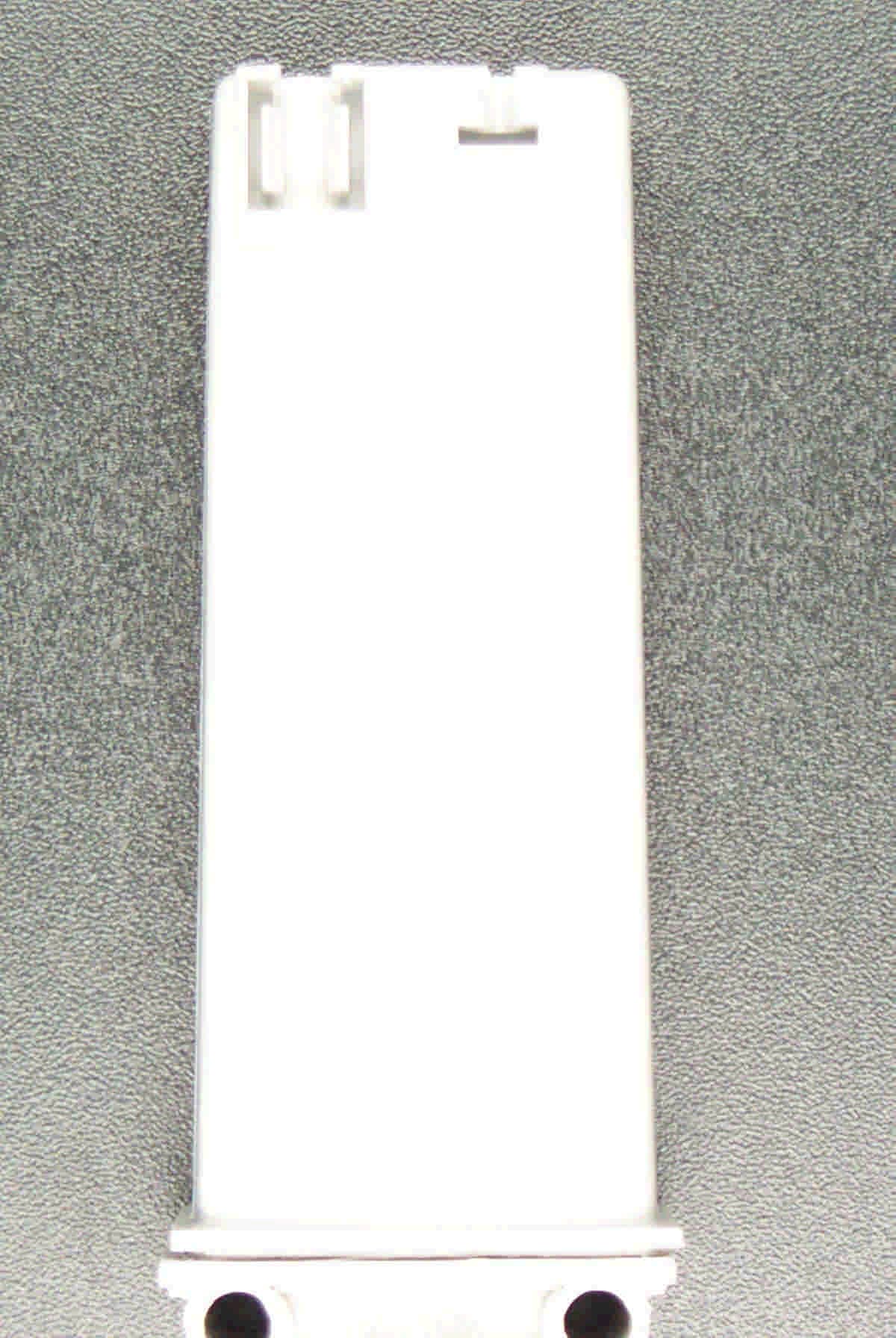
Click to zoom
Application Details
- Equipment Class
- CYY - Communications Receiver used w/Pt 15 Transmitter
- Date of Grant
- Jun 27, 2004
- Application Purpose
- Original Equipment
- Date of Application
- Jun 27, 2004
- Equipment Note
- Receiver of Tire Pressure Monitoring System
- Frequency Range
- 315.00000000 - 315.00000000
- Country
- Germany
Documents & Files
Document Text
Text extracted from the exhibit documents filed with the FCC. Open a document above to read the original.
Users Manual
TSS 2. Generation, “AUDI B6 / C6” Tire Safety System TSS 2nd. Generation,”AUDI B6 / C6” Dept. BEE Dokument Nr.: Document no.: Änderungsstand: Status of modification: Index: Index: 3530 27 004 003 00 c Bedienungsanleitung TSS 2. Generation, “AUDI B6 / C6 User Manual 2 nd Generation “TSS AUDI B6 / C6 freigegeben am /date of release 11.05.04 Titel: Bedienungsanleitung TSS 2. Generation, “AUDI B6 / C6” Title: User Manual 2 nd Generation “TSS AUDI B6 / C6” Dokument Nr.: 3530 27 004 003 00 Document no: Projekt: TSS 2. Generation, “AUDI B6 / C6” Project: Tire Safety System TSS 2nd. Generation,”AUDI B6 / C6” Current status: Index: Index: Änd.stand: Status of modification: Beschreibung: Description Erstellt / Datum: Prepared / date: Geprüft / Datum: Checked / date: Freigegeben / Datum: Released / date: c 00 Maintenance of WE transmitting power according to FCC Saric/ 11.05.04 Köninger/ 11.05.04 Denzler/ 11.05.04 Revision service Index: Index: Änd.stand: Status of modification: Beschreibung: Description Erstellt / Datum: Prepared / date: Geprüft / Datum: Checked / date: Freigegeben / Datum: Released / date: b 00 Maintenance of WE transmitting power according to FCC Saric/ 11.05.04 Köninger/ 11.05.04 Denzler/ 11.05.04 a 00 First version Köninger/ 07.05.04 Birringer/ 10.05.04 Denzler/ 10.05.04 TSS 2. Generation, “AUDI B6 / C6” Tire Safety System TSS 2nd. Generation,”AUDI B6 / C6” Dept. BEE Dokument Nr.: Document no.: Änderungsstand: Status of modification: Index: Index: 3530 27 004 003 00 c Bedienungsanleitung TSS 2. Generation, “AUDI B6 / C6 User Manual 2 nd Generation “TSS AUDI B6 / C6 freigegeben am /date of release 11.05.04 Contents: 1 SYSTEM AND FUNCTIONAL DESCRIPTION ................................................................................................. 3 1.1 SYSTEM DESCRIPTION................................................................................................................................................ 4 2 FUNCTIONAL DESCRIPTION ............................................................................................................................ 6 3 WARNING ALGORITHM..................................................................................................................................... 9 List of Figures: Figure 1: Modular mimic display, 2nd Generation TSS System B6/ C6 LowLine ................................................ 7 Figure 2: Modular mimic display, 2nd Generation TSS System C6 HighLine ...................................................... 8 TSS 2. Generation, “AUDI B6 / C6” Tire Safety System TSS 2nd. Generation,”AUDI B6 / C6” Dept. BEE Dokument Nr.: Document no.: Änderungsstand: Status of modification: Index: Index: 3530 27 004 003 00 c Bedienungsanleitung TSS 2. Generation, “AUDI B6 / C6 User Manual 2 nd Generation “TSS AUDI B6 / C6 freigegeben am /date of release 11.05.04 1 System and Functional Description Section 15.19: Labeling requirements This device complies with Part15 of the FCC Rules. Operation is subject to the following two conditions: (1) this device may not cause harmful interference, and (2) this device must accept any interference received, including interference that may cause undesired operation. Section 15.21: Information to the user The user manual or instruction manual for an intentional or unintentional radiator shall caution the user that makes changes or modifications not expressly approved by the party responsible for compliance could void the user’s authority to operate the equipment. TSS 2. Generation, “AUDI B6 / C6” Tire Safety System TSS 2nd. Generation,”AUDI B6 / C6” Dept. BEE Dokument Nr.: Document no.: Änderungsstand: Status of modification: Index: Index: 3530 27 004 003 00 c Bedienungsanleitung TSS 2. Generation, “AUDI B6 / C6 User Manual 2 nd Generation “TSS AUDI B6 / C6 freigegeben am /date of release 11.05.04 1.1 System Description The Tire Safety System (TSS) controls and monitors tire pressures. The system comprises the following components: B6 System: • 1 TSS control unit • 4 sets of wheel electronics including valve • 1 digital antenna C6 System, Low Line variant: C6 System, High Line variant: • 1 TSS control unit 1 TSS control unit • 4 sets of wheel electronics including valve 4 sets of wheel electronics including valve • 1 digital antenna 1 digital antenna 4 trigger transmitters The system's primary function is to monitor tire pressure during travel. An electronic mechanism mounted inside the tire measures tire pressure and temperature at regular intervals and transfers the values telemetrically via a HF transmission line to a reception antenna. In the receiver antenna, the radio data telegram is decoded and transferred to the control unit as a digital signal. The control unit evaluates the received data and forwards the information to the driver as required. This provides the driver with information on the necessary tire pressure or tire tension adjustments. The C6 High Line System also offers a bi-directional communication with the wheel electronics (trigger function). The benefits offered by the tire pressure control system are: • Safety An early warning signal is triggered on sudden pressure loss. “Blow-outs” caused by excessive flexing and then driving on inadequate tire pressure are avoided. The driver is prompted to adjust the tire pressure where necessary. • Comfort Tire handing is made simple. Using filling equipment at the fuel station and removing the valve cap is necessary only for correcting the tire pressure. • New tire developments TSS 2. Generation, “AUDI B6 / C6” Tire Safety System TSS 2nd. Generation,”AUDI B6 / C6” Dept. BEE Dokument Nr.: Document no.: Änderungsstand: Status of modification: Index: Index: 3530 27 004 003 00 c Bedienungsanleitung TSS 2. Generation, “AUDI B6 / C6 User Manual 2 nd Generation “TSS AUDI B6 / C6 freigegeben am /date of release 11.05.04 Tires with limp-home features avoid having to change a wheel immediately and render the spare wheel superfluous. Th…
Text truncated - open the document above for the full version.
External Photos
Annex B (External Photographs of the EUT) of test report R40458/2_Edition 2 EUT: TSS/DA3P and TSS/SG-G3/2 Manufacturer: BERU AG Examiner: Raimund BLASKDate of issue: 24 June 2004page 1 of 2 40458eut31.jpg: EUT, TSS/SG-G3/2 front view Annex B (External Photographs of the EUT) of test report R40458/2_Edition 2 EUT: TSS/DA3P and TSS/SG-G3/2 Manufacturer: BERU AG Examiner: Raimund BLASKDate of issue: 24 June 2004page 2 of 2 40458eut15.jpg: EUT, TSS/DA3P front view
Test Report
Königswinkel 10 32825 Blomberg Germany Phone+49 5235 9500-0 Fax+49 5235 9500-10 TEST REPORT Test Report Reference: R40458/2 Edition 1 Equipment under Test: Electronic Control Unit ECU, TSS/SG-G3/2, Serial-No. 200002003 Digital antenna 315 MHz TSS/DA3P, serial-No. 10001207 Applicant: BERU AG Manufacturer: BERU AG Test Laboratory (CAB) accredited by DATech e.V. in compliance with DIN EN ISO/IEC 17025 under the Reg. No. TTI-P-G071/94-11 and listed by FCC 31040/SIT1300F2 TEST REPORT REFERENCE: R40458/2 Edition 1 Examiner: Raimund BLASKDate of issue: 24 June 2004Page 2 of 20 Contents:Page 1IDENTIFICATION.....................................................................................................................................3 1.1APPLICANT....................................................................................................................................3 1.2MANUFACTURER..........................................................................................................................3 1.3DATES3 1.4TEST LABORATORY......................................................................................................................4 1.5RESERVATION...............................................................................................................................4 1.6NORMATIVE REFERENCES.........................................................................................................4 1.7TEST RESULTS..............................................................................................................................4 2TECHNICAL DATA OF EQUIPMENT......................................................................................................5 2.1DEVICE UNDER TEST...................................................................................................................5 2.2PERIPHERY DEVICES...................................................................................................................5 2.3MODIFICATIONS............................................................................................................................5 3OPERATIONAL STATES AND PHYSICAL BOUNDARIES.....................................................................6 4LIST OF TEST MODULES.......................................................................................................................7 4.1EMISSION.......................................................................................................................................7 4.2CONDUCTED EMISSIONS ON AC MAINS (150 kHz to 30 MHz)..................................................8 4.3RADIATED EMISSIONS (30 MHz to 1 GHz)..................................................................................9 5TEST RESULTS EMISSION TEST..........................................................................................................12 5.1CONDUCTED EMISSION TEST (150 kHz to 30 MHz)..................................................................12 5.2PRELIMINARY RADIATED EMISSION TEST (30 MHz to 1 GHz).................................................13 5.3FINAL RADIATED EMISSION TEST (30 MHz to 1 GHz)...............................................................14 6TEST EQUIPMENT AND ANCILLARIES USED FOR TESTS.................................................................16 7LIST OF ANNEXES..................................................................................................................................20 TEST REPORT REFERENCE: R40458/2 Edition 1 Examiner: Raimund BLASKDate of issue: 24 June 2004Page 3 of 20 1IDENTIFICATION 1.1APPLICANT Name:BERU AG Address:Mörikestraße 155 71602 Ludwigsburg Country:Germany Name for contact purposes:Mr. Zlatan Saric Phone:+49-7141-132-798 Fax:+49-7141-132-589 Mail address:[email protected] Applicant represented during the test by the following person: - 1.2MANUFACTURER Name:BERU AG Address:Mörikestraße 155 71602 Ludwigsburg Country:Germany Name for contact purposes:Mr. Zlatan Saric Phone:+49-7141-132-798 Fax:+49-7141-132-589 Mail address:[email protected] Applicant represented during the test by the following person: - 1.3DATES Date of receipt of test sample:17 May 2004 Start of test:17 May 2004 Finish of test:18 May 2004 TEST REPORT REFERENCE: R40458/2 Edition 1 Examiner: Raimund BLASKDate of issue: 24 June 2004Page 4 of 20 1.4TEST LABORATORY The tests were carried out at:PHOENIX TEST-LAB GmbH Königswinkel 10 D-32825 BlombergPhone: +49 (0) 52 35 / 95 00-0 GermanyFax:+49 (0) 52 35 / 95 00-10 Test engineer:Raimund Blask24 June 2004 namesignaturedate Test report checked: Bernd Steiner24 June 2004 namesignaturedate stamp 1.5RESERVATION T h i s t e s t r e p o r t i s o n l y v a l i d i n i t s o r i g i n a l f o r m. Any reproduction of its contents without written permission of the accredited test laboratory PHOENIX TEST-LAB GmbH is prohibited. The test results herein refer only to the tested sample. PHOENIX TEST-LAB GmbH is not responsible for any generalisations or conclusions drawn from these test results concerning further samples. Any modification of the tested samples is prohibited and leads to the invalidity of this test report. Each page necessarily contains the PHOENIX TEST-LAB Logo and the TEST REPORT REFERENCE. 1.6NORMATIVE REFERENCES [1] ANSI C63.4-2001 American National Standard for Methods of Measuring of Radio-Noise Emissions from Low-Voltage Electrical and Electronic Equipment in the Range of 9 kHz to 40 GHz. [2] FCC 47 CFR Part 15 (08 December 2003) Radio Frequency Devices 1.7TEST RESULTS The requirements of this test document are fulfilled by the equipment under test. The complete test results are presented in the following. TEST REPORT REFERENCE: R40458/2 Edition 1 Examiner: Raimund BLASKDate of issue: 24 June 2004Page 5 of 20 2TECHNICAL DATA OF EQUIPMENT 2.1DEVICE UNDER TEST Type of equipment:ECU Electronic Control Unit TSS/SG-G3/2 Digital Antenna 315 MHz: TSS/DA3P Type designation: TSS/SG-G…
Text truncated - open the document above for the full version.
Test Setup Photos
Annex A (Photographs of the test set-up) of test report R40458/2_Edition 2 EUT: TSS/DA3P and TSS/SG-G3/2 Manufacturer: BERU AG Examiner: Raimund BLASKDate of issue: 24 June 2004page 1 of 3 40458emi1.jpg: Test set-up preliminary radiated emission measurement 30 MHz to 1 GHz Annex A (Photographs of the test set-up) of test report R40458/2_Edition 2 EUT: TSS/DA3P and TSS/SG-G3/2 Manufacturer: BERU AG Examiner: Raimund BLASKDate of issue: 24 June 2004page 2 of 3 40458emi19.jpg: Test set-up final radiated emission measurement 30 MHz to 1 GHz. Annex A (Photographs of the test set-up) of test report R40458/2_Edition 2 EUT: TSS/DA3P and TSS/SG-G3/2 Manufacturer: BERU AG Examiner: Raimund BLASKDate of issue: 24 June 2004page 3 of 3 40458emi18.jpg: Test set-up conducted emission measurement
Contact Information
Applicant
Alexander Haerter
Technical Contact
Non-Technical Contact
BERU AGZlatan Saric
[email protected]+49 7141 132 798
Test Firm
Phoenix TestLab GmbHH. Altmaier
Technical Specifications
| # | Rule Parts | Frequency Range | Power Output |
|---|---|---|---|
| 1 | 15B | 315 MHz - 315 MHz | - |
Other Applications from Huf Baolong Electronics Bretten GmbH
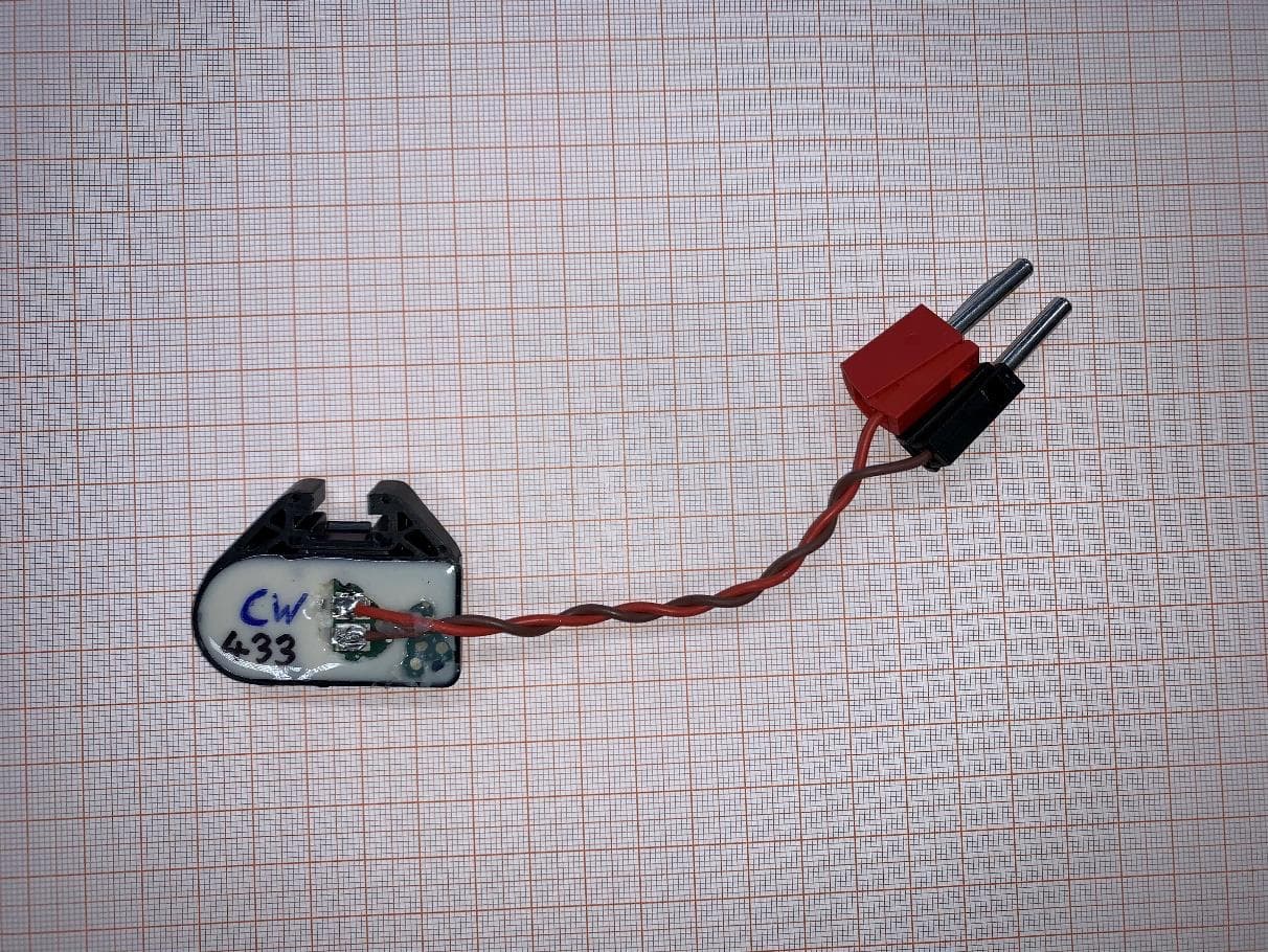
OYGTSSRE4AR
Jul 18, 2022TPMS Sensor S5.32 433 MHz
Equipment Class
DSC - Part 15 Security/Remote Control Transmitter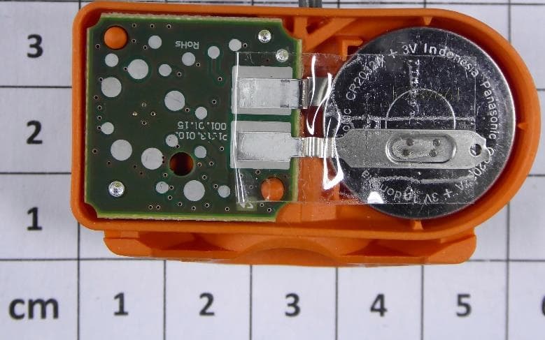
OYGTMSS5A2
Aug 12, 2020TPMS Sensor S5.xG Dual Band
Equipment Class
DSC - Part 15 Security/Remote Control Transmitter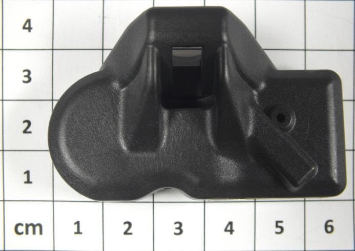
OYGTSSRE4UD
Dec 17, 2014TPMS Sensors of G3.8 Family (433.92 MHz)
Equipment Class
DSC - Part 15 Security/Remote Control Transmitter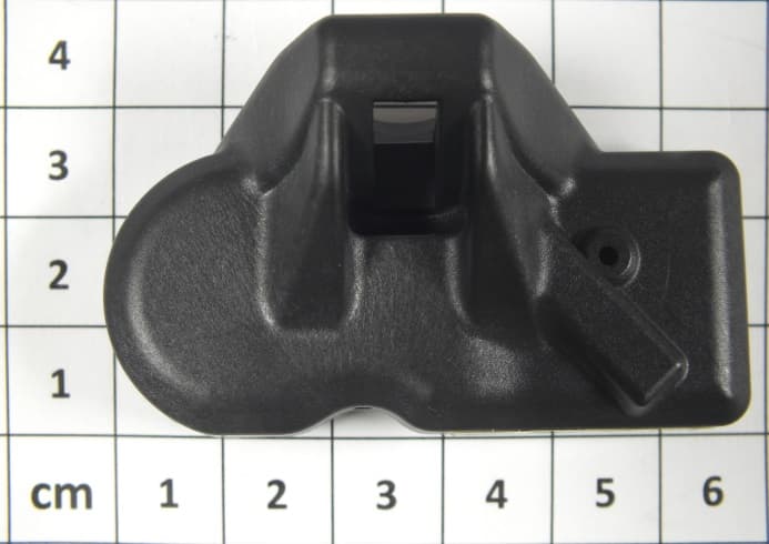
OYGTSSRE3UD
Dec 17, 2014Tire Pressure Monitoring System (TPMS)
Equipment Class
DSC - Part 15 Security/Remote Control TransmitterOYGTSSRE4UC
Aug 04, 2014TSSRE4UC
Equipment Class
DSC - Part 15 Security/Remote Control Transmitter