OYGTSSRE3PBTire Safety System
Huf Baolong Electronics Bretten GmbH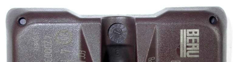
Click to zoom
Application Details
- Equipment Class
- DSC - Part 15 Security/Remote Control Transmitter
- Date of Grant
- Oct 23, 2006
- Application Purpose
- Original Equipment
- Date of Application
- Oct 23, 2006
- Equipment Note
- Tire Safety System
- Frequency Range
- 315.00000000 - 315.00000000
- Country
- Germany
Documents & Files
Document Text
Text extracted from the exhibit documents filed with the FCC. Open a document above to read the original.
Users Manual
Reifendruck-Kontrollsystem Tire pressure monitoring system Seite 1 von 4 1 Description of the system The tire pressure monitoring system is applied for the permanent control of the tire pressure during driving and also during standstill periods. An electronic system which is installed in the interior of the tire measures the tire pressure and the temperature in regular intervals and transmits information to a central control unit by means of a high frequency transmission line. The control unit evaluates the incoming data and transmits the information to the driver, if required. In the case of a puncture, the driver is given a warning, and he is also informed when the tire pressure should be corrected. 2 System components The tire pressure control system consists of the following components: • or 5 aluminium valves • 4 or 5 electronic units in the wheels (sensor and high-frequency sending unit) • 4 or 5 receiving antennas • a special connecting cable appropriate for high-frequency transmission, between the receiving antennas and the control unit • a control unit (high-frequency receiver and evaluation system) • option: keying device for entering a default pressure Figure 1: components of the tire pressure monitoring system At present, an individual output unit is not available, since the output of the messages to the driver is done via the driver information system belonging to the standard equipment. Reifendruck-Kontrollsystem Tire pressure monitoring system Seite 2 von 4 Figure 2: schematic representation of the system ́s layout in a vehicle 2.1 Electronic wheel unit The battery-based electronic wheel units are mounted inside the tires to measure the tire pressure and the temperature of the electronic wheel systems. Every electronic wheel unit has an individual code (ID), which is transmitted with every message. Furthermore, the data telegram includes information about the remaining service life of the battery. The measured data are transmitted from the wheel through a transmission point. A tire pressure monitoring system has to carry out two main functions: The recognition of a pressure loss and the measurement of the absolute pressure. For the measurement of the absolute pressure, a relatively low frequency of measurement data transmissions is sufficient, a pressure loss must be transmitted immediately. The electronic wheel system shifts automatically to the various operating modi in order to carry out these functions at a minimum power consumption. Transmitting intervals • Normally, every electronic wheel unit measures the tire pressure and the approximate temperature of the air in the tire every three seconds but if the measured values are stable, sending processes are carried out only every 54 seconds. • At a pressure loss of more than 0.2 bar per minute, the electronic wheel unit shifts temporarily to a high transmission frequency. It will then carry out measurements and sending processes every 0.8 seconds. This energy management allows battery-based operation with a sufficient service life. Reifendruck-Kontrollsystem Tire pressure monitoring system Seite 3 von 4 Abbildung 3: components of the tire pressure monitoring system The electronic wheel unit is combined with the aluminium valve to form a compact unit which is bolted to the standardized valve bore of the rim. Its design allows mounting in almost every known rim type. The electronic wheel unit includes an intelligent integrated sensor which is mounted on a circuit carrier and has been developed especially for this application. In its SMD housing, the two-chip integrated sensor contains a pressure sensor element and an ASIC (Application Specific Integrated Circuit) with temperature sensor, measurement acquisition unit and a signal conditioning unit. This sensor directly controls a high-frequency sending unit. The power supply to the sensor and the sending unit is done by an environmental friendly lithium battery which has been developed especially for the high demands on temperature resistance, acceleration resistance and service life. In combination with the tire monitoring control unit, the typical service life is 7 years. 2.2 Control Device The control device consists of a high-frequency receiving module, a control device plate with microprocessor control and the bus and diagnosis interfaces. It evaluates the received data and transmits the information to the driver information system. It is installed in a standard series housing. 3 High Frequency transmission The applied technique is a unidirectional high-frequency transmission of the measuring data from the wheel to the vehicle. The high-frequency transmission is carried out in the 433-MHz- range, the socalled ISM band or, in several countries, in the 315 MHz range. The system has been given approval by the telecommunication authorities of the relevant countries. The data sent by the electronic wheel system are received by the antennas mounted in the wheels and are transmitted to the control unit by screened twisted pair cables. Reifendruck-Kontrollsystem Tire pressure monitoring system Seite 4 von 4 4 FCC Requirements Section 15.19: Labeling requirements This device complies with Part15 of the FCC Rules. Operation is subject to the following two conditions: (1) this device may not cause harmful interference, and (2) this device must accept any interference received, including interference that may cause undesired operation. Section 15.21: Information to the user The user manual or instruction manual for an intentional or unintentional radiator shall caution the user that changes or modifications not expressly approved by the party responsible for compliance could void the user’s authority to operate the equipment. 5 IC statement according to RSS210 5.11 User Manual Operation is subject to the following two conditions: (1) this device may not cause interference, and (2) this device must accept any interference, including interference that may cause undesired operation o…
Text truncated - open the document above for the full version.
Cover Letter(s)
Federal Communications Commission 7435 Oakland Mills Road Columbia, MD 21046 Re: Justification Letter for Confidentiality of Internal Photos Our client’s product with the FCC ID: OYGTSSRE3PB is a Tire Safety System (Wheel Electronic). These devices will be installed in vehicle tires and are only serviceable by designated technicians. (Non-Consumer-Devices). Therefore our client also wants to hold the Internal Photos for this submission confidential. Sincerely, Strasskirchen, 23.10.2006 Thomas Ring Manager: Certification mikes-testingpartners gmbh ohmstrasse 2-4 94342 Strasskichen, Germany Phone: 0049 9424 9481 0 Fax: 0049 9424 9481 240
External Photos
FCC ID: OYGTSSRE3PB mikes-testingpartners gmbh File No. T31130-00-00XF, page 5 of 26 Ohmstrasse 2-4 x 94342 Strasskirchen Tel.:+49(0)9424-94810 x Fax:+49(0)9424-9481240 Rev. No. 1.1 3 EQUIPMENT UNDER TEST 3.1 Photo documentation of the EuT Wheel Electronic / TSSRE3Pb T31130-00-00XF External Photo Top view Wheel Electronic / TSSRE3Pb T31130-00-00XF External Photo Rear view
Test Report
FCC ID: OYGTSSRE3PB mikes-testingpartners gmbh File No. T31130-00-00XF, page 1 of 26 Ohmstrasse 2-4 x 94342 Strasskirchen Tel.:+49(0)9424-94810 x Fax:+49(0)9424-9481240 Rev. No. 1.1 EMI -- T E S T R E P O R T Test Report No. : T31130-00-00XF October 06,2006 ______________________________________________________________________________________________ Date of issue Type / Model Name : Wheel Electronic / TSSRE3Pb Product Description : Tire Safety System Applicant : BERU AG Address : Mörikestrasse 155 71636 Ludwigsburg Manufacturer : BERU AG Address : Mörikestrasse 155 71636 Ludwigsburg Licence holder : BERU AG Address : Mörikestrasse 155 71636 Ludwigsburg Test Result according to the standards listed in clause 1 test standards: Positive The test report merely corresponds to the test sample. It is not permitted to copy extracts of these test results without the written permission of the test DAT-P-207/05-00 laboratory. FCC ID: OYGTSSRE3PB mikes-testingpartners gmbh File No. T31130-00-00XF, page 2 of 26 Ohmstrasse 2-4 x 94342 Strasskirchen Tel.:+49(0)9424-94810 x Fax:+49(0)9424-9481240 Rev. No. 1.1 Contents 1 TEST STANDARDS 3 2 SUMMARY 4 3 EQUIPMENT UNDER TEST 5 3.1 PHOTO DOCUMENTATION OF THE EUT 5 3.3 POWER SUPPLY SYSTEM UTILISED 7 3.4 SHORT DESCRIPTION OF THE EQUIPMENT UNDER TEST (EUT) 7 4 TEST ENVIRONMENT 8 4.1 ADDRESS OF THE TEST LABORATORY 8 4.2 ENVIRONMENTAL CONDITIONS 8 4.3 STATEMENT OF THE MEASUREMENT UNCERTAINTY 8 4.4 MEASUREMENT PROTOCOL FOR FCC, VCCI AND AUSTEL 8 5 TEST CONDITIONS AND RESULTS FOR 315 MHZ TRANSMITTER 10 5.1 CONDUCTED EMISSIONS 10 5.2 RADIATED POWER OF THE FUNDAMENTAL WAVE 11 5.3 RADIATED EMISSIONS (ELECTRIC FIELD) 30 MHZ – 18 GHZ 13 5.4 CORRECTION FOR PULSE OPERATION (DUTY CYCLE) 18 5.5 EMISSION BANDWIDTH 22 5.6 SIGNAL DEACTIVATION 24 6 USED TEST EQUIPMENT AND ACCESSORIES 26 FCC ID: OYGTSSRE3PB mikes-testingpartners gmbh File No. T31130-00-00XF, page 3 of 26 Ohmstrasse 2-4 x 94342 Strasskirchen Tel.:+49(0)9424-94810 x Fax:+49(0)9424-9481240 Rev. No. 1.1 1 TEST STANDARDS The tests were performed according to following standards: FCC Rules and Regulations Part 15 Subpart C - Intentional Radiators (October 01, 2005) Part 15, Subpart C, Section 15.231 Periodic operation in the band 40.66-40.70 MHz and above 70 MHz §15.231(a) Signal deactivation §15.231(b) Radiated emissions, Fundamental & Harmonics §15.231(c) Emission Bandwidth Part 15, Subpart C, Section 15.35(c) Correction for Pulse Operation (Duty Cycle) Part 15, Subpart C, Section 15.207(a) AC Line conducted emissions Part 15, Subpart C, Section 15.209(a) Radiated emissions, general requirements FCC ID: OYGTSSRE3PB mikes-testingpartners gmbh File No. T31130-00-00XF, page 4 of 26 Ohmstrasse 2-4 x 94342 Strasskirchen Tel.:+49(0)9424-94810 x Fax:+49(0)9424-9481240 Rev. No. 1.1 2 SUMMARY GENERAL REMARKS: All radiated tests have been performed on samples which are in orginal state. For activating the EuT it have been lied into a pressure box where it was possible to change the pressure. (See test setup photos) All other tests have been performed at PCB without any cabinet where it was possible to activate the EuT when we switch on the DC power with an external DC Power supply. FINAL ASSESSMENT: The equipment under test fulfills the EMI requirements cited in clause 1 test standards. Date of receipt of test sample : acc. to storage records Testing commenced on : September 20,2006 Testing concluded on : October 06,2006 Checked by: Tested by: Thomas Weise Dipl.-Ing.(FH) Laboratory Manager Fischer Xaver FCC ID: OYGTSSRE3PB mikes-testingpartners gmbh File No. T31130-00-00XF, page 7 of 26 Ohmstrasse 2-4 x 94342 Strasskirchen Tel.:+49(0)9424-94810 x Fax:+49(0)9424-9481240 Rev. No. 1.1 Power supply system utilised Power supply voltage : 3,0 V / DC 3.4 Short description of the Equipment under Test (EuT) The tire pressure monitoring system is applied for the permanent control of the tire pressure during driving and also during standstill periods. An electronic system which is installed in the interior of the tire measures the tire pressure and the temperature in regular intervals and transmits information to a central control unit by means of a high frequency transmission line. The control unit evaluates the incoming data and transmits the information to the driver, if required. In the case of a puncture, the driver is given a warning, and he is also informed when the tire pressure should be corrected. Number of tested samples: 1 Serial number: Prototype EuT operation mode: The equipment under test was operated during the measurement under the following conditions: - TX-mode at frequency 315 MHz EuT configuration: (The CDF filled by the applicant can be viewed at the test laboratory.) The following peripheral devices and interface cables were connected during the measurements: - Model : - Model : - Model : - Model : - Model : - Model : FCC ID: OYGTSSRE3PB mikes-testingpartners gmbh File No. T31130-00-00XF, page 8 of 26 Ohmstrasse 2-4 x 94342 Strasskirchen Tel.:+49(0)9424-94810 x Fax:+49(0)9424-9481240 Rev. No. 1.1 4 TEST ENVIRONMENT 4.1 Address of the test laboratory mikes-testingpartners gmbh Ohmstrasse 2-4 94342 Strasskirchen Germany 4.2 Environmental conditions During the measurement the environmental conditions were within the listed ranges: Temperature: 15-35 ° C Humidity: 30-60 % Atmospheric pressure: 86-106 kPa 4.3 Statement of the measurement uncertainty The data and results referenced in this document are true and accurate. The reader is cautioned that there may be errors within the calibration limits of the equipment and facilities. The measurement uncertainty was calculated for all measurements listed in this test report acc. to CISPR 16-4-2 /11.2003 „Uncertainties, statistics and limit modelling – Uncertainty in EMC measurements“ and is documented in the quality system acc. to DIN EN ISO/IEC 17025. Furthermore, component and process variability of devices similar to that tested may result in additional deviation. The m…
Text truncated - open the document above for the full version.
Test Setup Photos
FCC ID: OYGTSSRE3PB mikes-testingpartners gmbh File No. T31130-00-00XF, page 11 of 26 Ohmstrasse 2-4 x 94342 Strasskirchen Tel.:+49(0)9424-94810 x Fax:+49(0)9424-9481240 Rev. No. 1.1 5.2 Radiated power of the fundamental wave For test instruments and accessories used see section 6 Part CPR 2. 5.2.1 Description of the test location Test location: OATS1 Test distance: 3 metres 5.2.2 Photo documentation of the test set-up FCC ID: OYGTSSRE3PB mikes-testingpartners gmbh File No. T31130-00-00XF, page 13 of 26 Ohmstrasse 2-4 x 94342 Strasskirchen Tel.:+49(0)9424-94810 x Fax:+49(0)9424-9481240 Rev. No. 1.1 5.3 Radiated emissions (electric field) 30 MHz – 18 GHz For test instruments and accessories used see section 6 Part SER 2, SER 3. 5.3.1 Description of the test location Test location: OATS1 Anechoic Chamber A2 5.3.2 Photo documentation of the test set-up FCC ID: OYGTSSRE3PB mikes-testingpartners gmbh File No. T31130-00-00XF, page 14 of 26 Ohmstrasse 2-4 x 94342 Strasskirchen Tel.:+49(0)9424-94810 x Fax:+49(0)9424-9481240 Rev. No. 1.1
Contact Information
Applicant
Alexander Haerter
Test Firm
CSA Group Bayern GmbHThomas Weise
Technical Specifications
| # | Rule Parts | Frequency Range | Power Output |
|---|---|---|---|
| 1 | 15.231 | 315 MHz - 315 MHz | - |
Other Applications from Huf Baolong Electronics Bretten GmbH
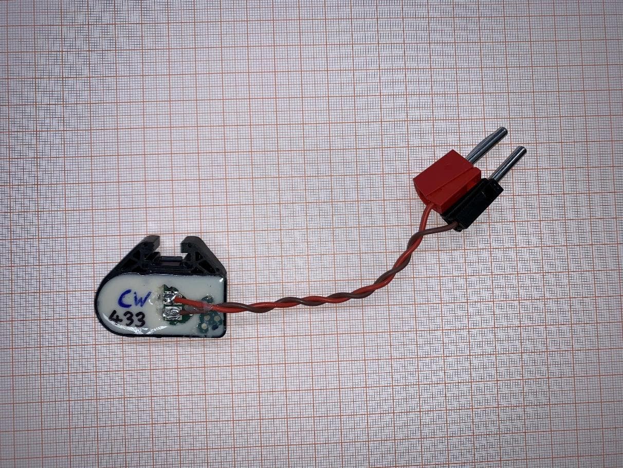
OYGTSSRE4AR
Jul 18, 2022TPMS Sensor S5.32 433 MHz
Equipment Class
DSC - Part 15 Security/Remote Control Transmitter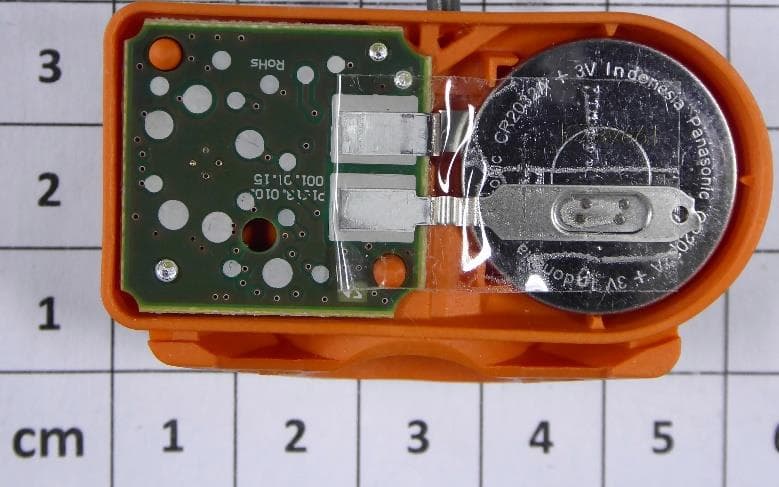
OYGTMSS5A2
Aug 12, 2020TPMS Sensor S5.xG Dual Band
Equipment Class
DSC - Part 15 Security/Remote Control Transmitter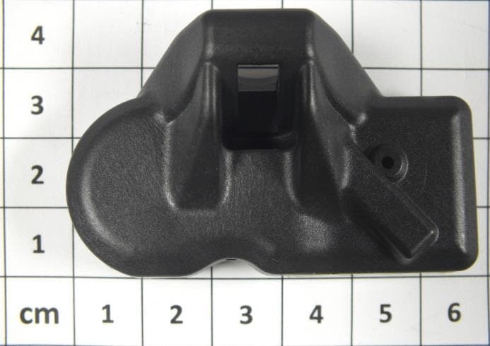
OYGTSSRE4UD
Dec 17, 2014TPMS Sensors of G3.8 Family (433.92 MHz)
Equipment Class
DSC - Part 15 Security/Remote Control Transmitter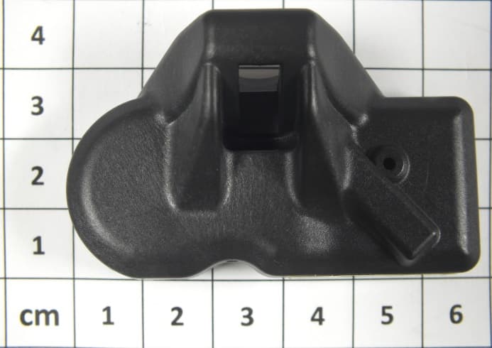
OYGTSSRE3UD
Dec 17, 2014Tire Pressure Monitoring System (TPMS)
Equipment Class
DSC - Part 15 Security/Remote Control TransmitterOYGTSSRE4UC
Aug 04, 2014TSSRE4UC
Equipment Class
DSC - Part 15 Security/Remote Control Transmitter