OYGTSSRE3TDTire Safety System
Huf Baolong Electronics Bretten GmbH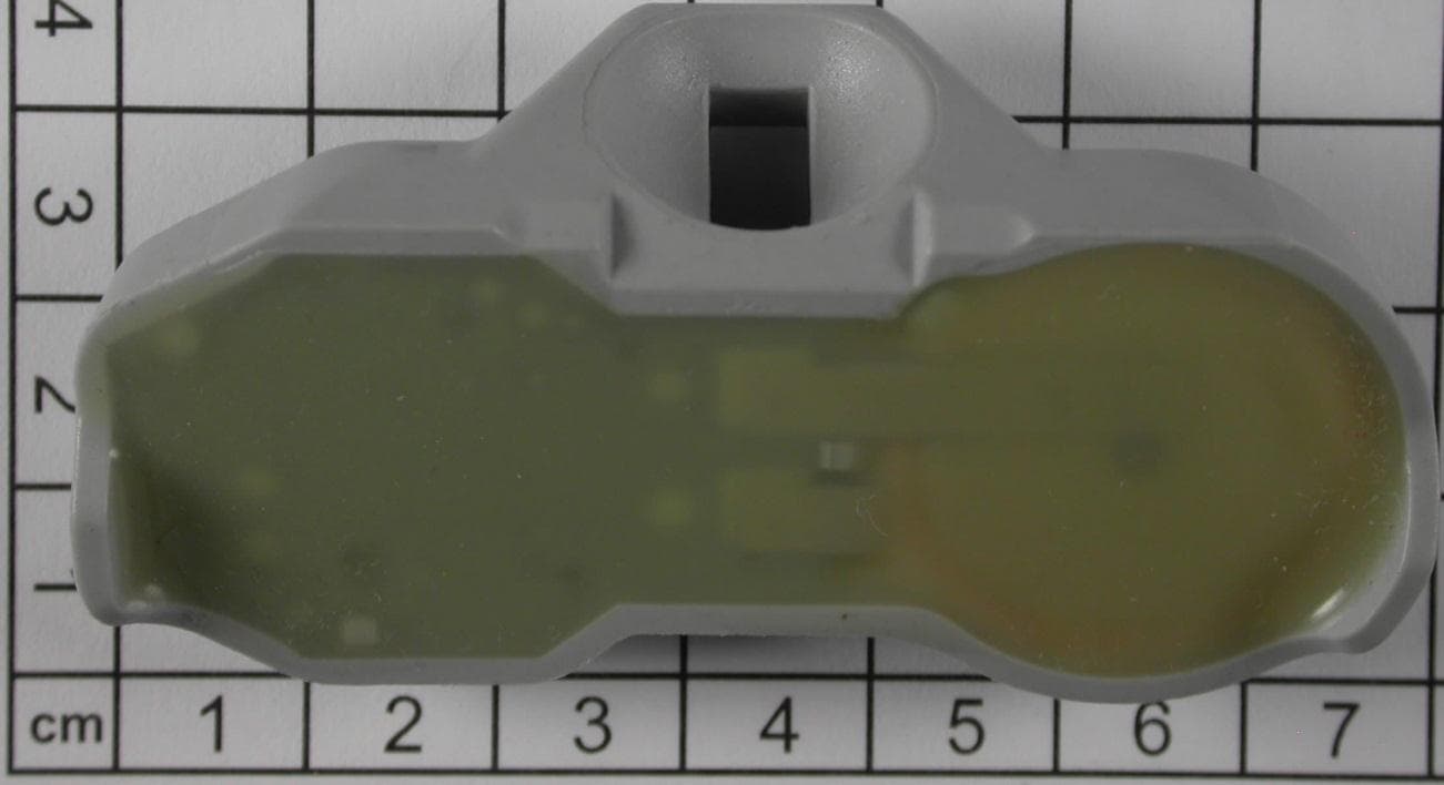
Click to zoom
Application Details
- Equipment Class
- DSC - Part 15 Security/Remote Control Transmitter
- Date of Grant
- Jun 24, 2012
- Application Purpose
- Original Equipment
- Date of Application
- Jun 21, 2012
- Equipment Note
- Tire Safety System
- Frequency Range
- 315.00000000 - 315.00000000
- Country
- Germany
Documents & Files
Document Text
Text extracted from the exhibit documents filed with the FCC. Open a document above to read the original.
Users Manual
USER’S MANUAL & COMPLIANCE STATEMENT May 30, 2012 Huf Electronics Bretten GmbH Gewerbestrasse 40, 75015 Bretten Germany Tire Pressure Monitoring System (TPMS) Model(s): TSSRE3Td The device under test is manufactured by the grantee (Huf Electronics Bretten) and sold as an OEM prod uct for cars. Therefore, we will not supply a separate user’s manual. Huf Electronics Bretten will supply this document to the reseller/dist ributor dictating what must be included in the end user’s manual for the vehicle. INFORMATION TO BE INCLUDED IN THE END USER’S MANUAL The following information must be included in the end user’s manual to ensure continued FCC and Industry Can ada regulatory compliance. +++++++++++++++++++++++++++++++++++++++++++++++++++++++++++++++++++++++++++++ FCC ID: OYGTSSRE3TD IC: 3702A-TSSRE3TD This device complies with Part 15 of the FCC rules a nd with RSS-210 of Industry Canada. Operation is subject to the following two conditions: (1) this device may not cause harmful interference, and (2) this device must accept any interference received, including interference that may cause undesired operation. WARNING: Changes or modifications not expressly approved by the party re sp onsible for compliance could void the user’s authority to operate the equipment. ++++++++++++++++++++++++++++++++++++++++++++++++++++++++++++++++++++++++++++
External Photos
Attachment A to File No.: T36045-00 1 P h o t o d o c u m e n t a t i o n o f t h e E U T 1.1 External views TSSRE3Td:
ID Label/Location Info
Huf Electronics Bretten Tire Pressure Monitoring Systems Label and location no. description content text height mm text width mm 1 customer logo symbol --- --- 2 customer part number part number 1.6 16.0 3 FCC ID (USA) FCC ID: OYGTSSRE3TD 1.2 15.0 4 Other country approvals Other homologations see owner manual 1.0 13.0 11.0 5 serial number (dec, 10 character) nnnnnnnnnn 1.5 11.0 6 hex wrench size 11mm Symbol 3.4 4.0 7 torque for mounting screw 4Nm 1.4 4.0 8 date of manufacture dd/mm/yy 1.3 7.0 9 frequency 315MHz 1.3 6.0 10 number of final test station (2 ch.) nn 1.3 2.0 11 model designation TSSRE3Td 1.5 3.5 12 Manufacturer name Huf 1.5 3.5 13 Data Matrix Code 315snnnnnnnnnn 7.5 7.5 14 wheeled bin symbol Symbol 4.0 3.8 15 IC ID (Canada) IC: 3702A-TSSRE3TD 1.2 15.0 16 country of origin Germany 1.5 8.0 17 legend for model Model: 1.5 6.4 18 RCB ID (Japan) 204-260004 1.2 14.0 19 CMIIT ID (China) CMIIT ID: 2011DJ4971 1.2 15.0 2012-05-30 page 1 of 2 Huf Electronics Bretten Tire Pressure Monitoring Systems Label and location Model: TSSRE3Td 2012-05-30 page 2 of 2
Test Report
FCC ID: OYGTSSRE3TD mikes-testingpartners gmbh File No. T36045-00-00HU, page 1 of 33 Ohmstrasse 2-4 94342 STRASSKIRCHEN GERMANY Tel.:+49(0)9424-94810 Fax: +49(0)9424-9481240 Rev. No. 1.1, 05.11.2008 EMI − T E S T R E P O R T - FCC Part 15.231 - Test Report No. : T36045-00-00HU 29. May 2012 ______________________________________________________________________________________________ Date of issue Type / Model Name : Wheel Electronic / TSSRE3Td Product Description : Tire Safety System Applicant : Huf Electronics Bretten GmbH Address : Gewerbestr. 40 75015 Bretten Germany Manufacturer : Huf Electronics Bretten GmbH Address : Gewerbestr. 40 75015 Bretten Germany Licence holder : Huf Electronics Bretten GmbH Address : Gewerbestr. 40 75015 Bretten Germany Test Result according to the standards listed in clause 1 test standards: POSITIVE The test report merely corresponds to the test sample. It is not permitted to copy extracts of these test results without the written permission of the test laboratory. FCC ID: OYGTSSRE3TD mikes-testingpartners gmbh File No. T36045-00-00HU, page 2 of 33 Ohmstrasse 2-4 94342 STRASSKIRCHEN GERMANY Tel.:+49(0)9424-94810 Fax: +49(0)9424-9481240 Rev. No. 1.1, 05.11.2008 Contents 1 T E S T S T A N D A R D S 3 2 S U M M A R Y 4 3 E Q U I P M E N T U N D E R T E S T 6 3.1 Photo documentation of the EUT – See Attachment A 6 3.2 Power supply system utilised 6 3.3 Short description of the Equipment under Test (EUT) 6 4 T E S T E N V I R O N M E N T 7 4.1 Address of the test laboratory 7 4.2 Environmental conditions 7 4.3 Statement of the measurement uncertainty 7 4.4 Measurement Protocol for FCC, VCCI and AUSTEL 7 5 T E S T C O N D I T I O N S A N D R E S U L T S 9 5.1 Conducted emissions 9 5.2 Field strength of the fundamental wave 10 5.3 Spurious emissions (magnetic field) 9 kHz – 30 MHz 12 5.4 Spurious emissions radiated (electric field) 14 5.5 Correction for pulse operation (duty cycle) 18 5.6 Emission bandwidth 22 5.7 On / Off Period 25 5.8 Signal deactivation 29 6 U S E D T E S T E Q U I P M E N T A N D A C C E S S O R I E S 33 A T T A C H M E N T A FCC ID: OYGTSSRE3TD mikes-testingpartners gmbh File No. T36045-00-00HU, page 3 of 33 Ohmstrasse 2-4 94342 STRASSKIRCHEN GERMANY Tel.:+49(0)9424-94810 Fax: +49(0)9424-9481240 Rev. No. 1.1, 05.11.2008 1 T E S T S T A N D A R D S The tests were performed according to following standards: FCC Rules and Regulations Part 15, Subpart A - General (October, 2011) Part 15, Subpart A, Section 15.31 Measurement standards Part 15, Subpart A, Section 15.33 Frequency range of radiated measurements Part 15, Subpart A, Section 15.35 Measurement detector functions and bandwidths FCC Rules and Regulations Part 15, Subpart C - Intentional Radiators (October, 2011) Part 15, Subpart C, Section 15.203 Antenna requirement Part 15, Subpart C, Section 15.204 External radio frequency power amplifiers and antenna modifications Part 15, Subpart C, Section 15.205 Restricted bands of operation Part 15, Subpart C, Section 15.207 Conducted limits Part 15, Subpart C, Section 15.209 Radiated emission limits, general requirements Part 15, Subpart C, Section 15.231 Periodic operation in the band 40.66-40.70 MHz and above 70 MHz ANSI C63.4: 2003 Methods of Measurement of Radio-Noise Emissions from Low- Voltage Electrical and Electronic Equipment in the Range of 9 kHz to 40 GHz. ANSI C95.1: 1992 IEEE Standard for Safety Levels with respect to Human Exposure to Radio Frequency Electromagnetic Fields, 3 kHz to 300 GHz CISPR 16-4-2: 2003 Uncertainty in EMC measurement CISPR 22: 2005 Information technology equipment EN 55022: 2006 FCC ID: OYGTSSRE3TD mikes-testingpartners gmbh File No. T36045-00-00HU, page 4 of 33 Ohmstrasse 2-4 94342 STRASSKIRCHEN GERMANY Tel.:+49(0)9424-94810 Fax: +49(0)9424-9481240 Rev. No. 1.1, 05.11.2008 2 S U M M A R Y GENERAL REMARKS: All radiated tests have been performed on samples which are in original state. FCC ID: OYGTSSRE3TD mikes-testingpartners gmbh File No. T36045-00-00HU, page 5 of 33 Ohmstrasse 2-4 94342 STRASSKIRCHEN GERMANY Tel.:+49(0)9424-94810 Fax: +49(0)9424-9481240 Rev. No. 1.1, 05.11.2008 The EUT has an incorporated antenna and is powered by a primary battery. The manufacturer declares following transmitting intervals: - Normal Operation mode: In normal operation mode, the electronic wheel unit measures the tire pressure and the approximate temperature of the air in the tire every three seconds but if the measured values are stable, sending processes are carried out only every 54 seconds. - Fast send mode: When a pressure loss > 0.2 bar on the last sent pressure value is detected, the wheel electronics switch immediately to fast-send mode. In this situation, the wheel electronics measure and send every 0.8 seconds for 255s. After this period of time it falls to the normal operation mode back. FINAL ASSESSMENT: The equipment under test fulfills the EMI requirements cited in clause 1 test standards. Date of receipt of test sample : acc. to storage records Testing commenced on : 10. May 2012 Testing concluded on : 14. May 2012 Checked by: Tested by: Klaus Gegenfurtner Dipl.-Ing.(FH) Manager Radio Group Markus Huber FCC ID: OYGTSSRE3TD mikes-testingpartners gmbh File No. T36045-00-00HU, page 6 of 33 Ohmstrasse 2-4 94342 STRASSKIRCHEN GERMANY Tel.:+49(0)9424-94810 Fax: +49(0)9424-9481240 Rev. No. 1.1, 05.11.2008 3 E Q U I P M E N T U N D E R T E S T 3.1 Photo documentation of the EUT – See Attachment A 3.2 Power supply system utilised Power supply voltage : 3.0 V / DC (Lithium battery) 3.3 Short description of the Equipment under Test (EUT) The Wheel electronics measure the tire pressure and the air temperature in the tire and send these via a set radio route together with the residual battery life and the code (ID) to the digital antenna. For exactly description please refer to the technical documents. Number of tested samples: 2 Serial number: Pre production sample EUT operation mode: Th…
Text truncated - open the document above for the full version.
Test Setup Photos
FCC ID: OYGTSSRE3TD mikes-testingpartners gmbh File No. T36045-00-00HU, page 10 of 33 Ohmstrasse 2-4 94342 STRASSKIRCHEN GERMANY Tel.:+49(0)9424-94810 Fax: +49(0)9424-9481240 Rev. No. 1.1, 05.11.2008 5.2 Field strength of the fundamental wave For test instruments and accessories used see section 6 Part CPR 2. 5.2.1 Description of the test location Test location: OATS1 Test distance: 3 metres 5.2.2 Photo documentation of the test set-up 5.2.1 Applicable standard According to FCC Part 15C, Section 15.231(e): The field strength of emissions from intentional radiators shall not exceed the effective field strength limits. 5.2.2 Description of Measurement The radiated power of the fundamental wave from the EUT is measured in the frequency range of 30 to 1000 MHz using a tuned receiver and appropriate broadband linearly polarized antennas. Measurements between 30 MHz and 1000 MHz are made with 120 kHz/6 dB bandwidth and quasi-peak detection. Table top equipment is placed on a 1.0 X 1.5 metres non-conducting table 80 centimetres above the ground plane. Floor standing equipment is placed directly on the turntable/ground plane. The set up of the EUT will be in accordance to ANSI C63.4. The Interface cables that are closer than 40 centimetres to the ground plane are bundled in the centre in a serpentine fashion so they are at least 40 centimetres from the ground plane. Cables to simulators/testers (if used in this test) are routed through the centre of the table and to a screen room located outside the test area. The antenna was positioned 3, 10 or 30 metres horizontally from the EUT. To locate maximum emissions from the test sample the antenna is varied in height from 1 to 4 metres, measurement scans are made in horizontal and vertical antenna polarization’s and the EUT is rotated 360 degrees. The resolution bandwidth during the measurement is as follows: 30 MHz – 1000 MHz: RBW: 120 kHz FCC ID: OYGTSSRE3TD mikes-testingpartners gmbh File No. T36045-00-00HU, page 12 of 33 Ohmstrasse 2-4 94342 STRASSKIRCHEN GERMANY Tel.:+49(0)9424-94810 Fax: +49(0)9424-9481240 Rev. No. 1.1, 05.11.2008 5.3 Spurious emissions (magnetic field) 9 kHz – 30 MHz For test instruments and accessories used see section 6 Part SER 1. 5.3.1 Description of the test location Test location: OATS1 Test distance: 3 metres 5.3.2 Photo documentation of the test set-up 5.3.3 Applicable standard According to FCC Part 15C, Section 15.209: The emissions from intentional radiators shall not exceed the effective field strength limits. 5.3.4 Description of Measurement The magnetic field strength from the EUT will be measured on an open area test site in the frequency range of 9 kHz to 30 MHz using a tuned receiver and a shielded loop antenna. The set up of the Equipment under test will be in accordance to ANSI C63.4. The antenna was positioned 3, 10 or 30 meters horizontally from the EUT. Measurements have been made in all three orthogonal axes and the shielded loop antenna was rotated to locate the maximum of the emissions. In the case where larger measuring distances are required the results will extrapolated based on the values measured on the closer distances according to Section 15.31(f)(2)(2). The final measurement will be performed with an EMI Receiver set to Quasi Peak detector except for the frequency bands 9 kHz to 90 kHz and 110 to 490 kHz where an average detector will be used according to Section 15.209(d)(2). FCC ID: OYGTSSRE3TD mikes-testingpartners gmbh File No. T36045-00-00HU, page 14 of 33 Ohmstrasse 2-4 94342 STRASSKIRCHEN GERMANY Tel.:+49(0)9424-94810 Fax: +49(0)9424-9481240 Rev. No. 1.1, 05.11.2008 5.4 Spurious emissions radiated (electric field) For test instruments and accessories used see section 6 Part SER 2, SER 3. 5.4.1 Description of the test location Test location: OATS1 Anechoic Chamber A2 Test distance: 3 metres 5.4.2 Photo documentation of the test set-up FCC ID: OYGTSSRE3TD mikes-testingpartners gmbh File No. T36045-00-00HU, page 18 of 33 Ohmstrasse 2-4 94342 STRASSKIRCHEN GERMANY Tel.:+49(0)9424-94810 Fax: +49(0)9424-9481240 Rev. No. 1.1, 05.11.2008 5.5 Correction for pulse operation (duty cycle) For test instruments and accessories used see section 6 Part DC. 5.5.1 Description of the test location Test location: AREA4 5.5.2 Photo documentation of the test set-up 5.5.3 Applicable standard According to FCC Part 15C, Section 15.35(c): The emissions from intentional radiators shall not exceed the effective field strength limits. 5.5.4 Test result The Duty cycle factor (dB) is calculated applying the following formula: KE= 20 log ((tiB)/100) KE: pulse operation correction factor (dB) tiB pulse duration for one pulse (ms) Maximum transmitting duration in every 100ms period: KE= 20 log ((10.136)/100) = -19.88 dB max. KE accd. FCC regulation = -20.0 dB Remarks: FCC ID: OYGTSSRE3TD mikes-testingpartners gmbh File No. T36045-00-00HU, page 22 of 33 Ohmstrasse 2-4 94342 STRASSKIRCHEN GERMANY Tel.:+49(0)9424-94810 Fax: +49(0)9424-9481240 Rev. No. 1.1, 05.11.2008 5.6 Emission bandwidth For test instruments and accessories used see section 6 Part MB. 5.6.1 Description of the test location Test location: AREA4 5.6.2 Photo documentation of the test set-up 5.6.3 Applicable standard According to FCC Part 15C, Section 15.231(c): The bandwidth of the emission shall not exceed the effective limits. 5.6.4 Description of Measurement The measurement was performed conducted with intentional modulation using a spectrum analyser. The analyser span was set wide enough to capture the most of the power envelope of the signal. The function “20-dB-down” is used to determine the BW. For an overview on the adjacent restricted bands the span was set as wide as needed to show that the restricted bands are not affected. FCC ID: OYGTSSRE3TD mikes-testingpartners gmbh File No. T36045-00-00HU, page 25 of 33 Ohmstrasse 2-4 94342 STRASSKIRCHEN GERMANY Tel.:+49(0)9424-94810 Fax: +49(0)9424-9481240 Rev. No. 1.1, 05…
Text truncated - open the document above for the full version.
Contact Information
Applicant
Alexander Haerter
Technical Contact
mikes-testingpartners gmbhMarkus Huber
[email protected]+49-9424-9481
Ohmstr. 2-4 · Strasskirchen · Germany
Test Firm
CSA Group Bayern GmbHThomas Weise
Technical Specifications
| # | Rule Parts | Frequency Range | Power Output |
|---|---|---|---|
| 1 | 15.231(e) | 315 MHz - 315 MHz | - |
Other Applications from Huf Baolong Electronics Bretten GmbH
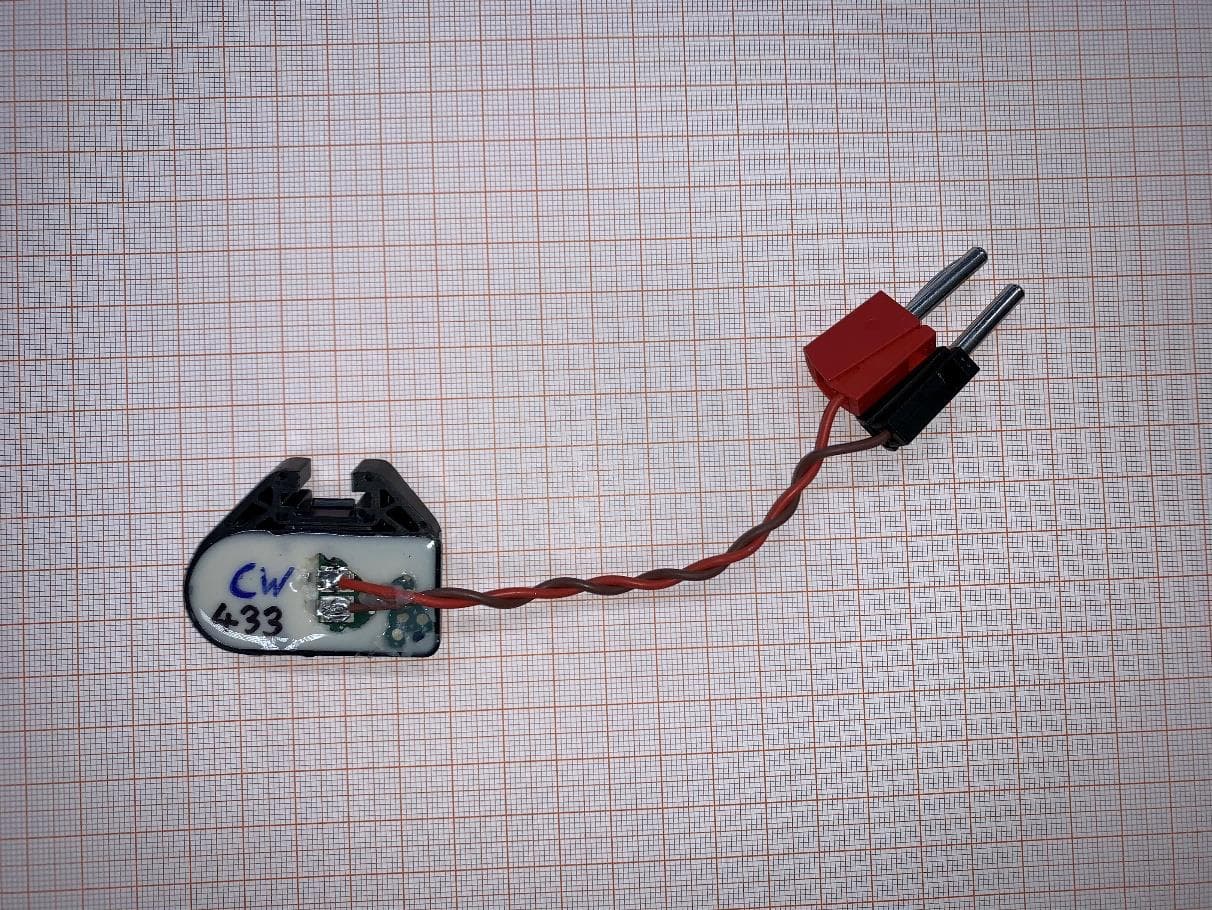
OYGTSSRE4AR
Jul 18, 2022TPMS Sensor S5.32 433 MHz
Equipment Class
DSC - Part 15 Security/Remote Control Transmitter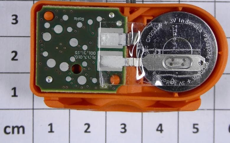
OYGTMSS5A2
Aug 12, 2020TPMS Sensor S5.xG Dual Band
Equipment Class
DSC - Part 15 Security/Remote Control Transmitter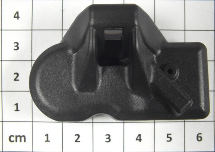
OYGTSSRE4UD
Dec 17, 2014TPMS Sensors of G3.8 Family (433.92 MHz)
Equipment Class
DSC - Part 15 Security/Remote Control Transmitter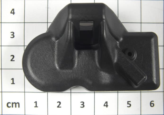
OYGTSSRE3UD
Dec 17, 2014Tire Pressure Monitoring System (TPMS)
Equipment Class
DSC - Part 15 Security/Remote Control TransmitterOYGTSSRE4UC
Aug 04, 2014TSSRE4UC
Equipment Class
DSC - Part 15 Security/Remote Control Transmitter