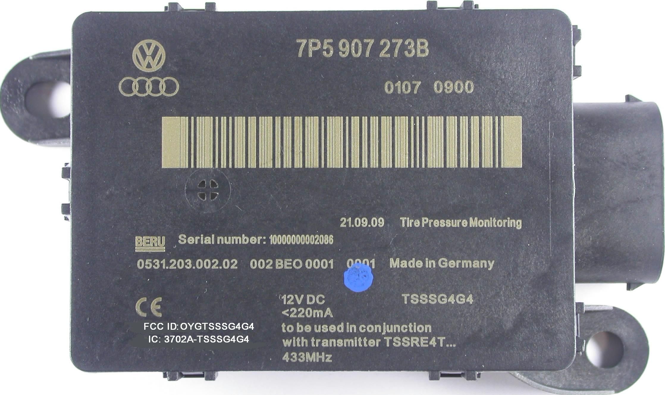
OYGTSSSG4G4Tyre Pressure Monitor System
Huf Baolong Electronics Bretten GmbH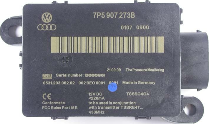
Click to zoom
Application Details
- Equipment Class
- CYY - Communications Receiver used w/Pt 15 Transmitter
- Date of Grant
- Dec 14, 2009
- Application Purpose
- Original Equipment
- Date of Application
- Dec 14, 2009
- Equipment Note
- Tyre Pressure Monitor System
- Frequency Range
- 433.92000000 - 433.92000000
- Country
- Germany
Documents & Files
Document Text
Text extracted from the exhibit documents filed with the FCC. Open a document above to read the original.
Users Manual
SYSTEM DESCRIPTION TPM KOMFORT ECU 1.1 TPM FUNCTIONALITY The main function of the TPM system is to monitor all four tyre pressures during driving operation and at standstill. LF trigger transmitters request periodically the wheel electronics to send datagrams containing information about tyre pressure and temperature. The system is able to detect the wheels fitted to the vehicle and their relative installation positions. This is achieved by analysing the triggering position and by performing a statistical analysis of the received information. 1.1.1 TPM System Interfaces The trigger transmitter interfaces with the TPM Komfort ECU by means of a dedicated & proprietary LIN bus. The TPM control unit diagnoses the individual system components. The TPM control module interfaces with the Driver Information Panel (DIP) and the Infotainment Unit (ZAB) by means of the Komfort CAN network. 1.1.2 TPM User Interface The interface with the user is made via the ZAB and the DIP. The DIP shows to the driver any warnings in the form of TPM specific symbols and text. The ZAB presents information regarding the state and condition of each tyre pressure. The driver requests a system calibration (system learning) through the ZAB (shown below). 1.1.3 TPM System Configuration There are two possible system configurations, dependent on radio frequency (RF) used: - 315 MHz configuration for some Asian and African markets - 433 MHz configuration for ROW (including NAR & Europe). 1.2 WHEEL MANAGEMENT 1.2.1 Overview The TPM system detects automatically the wheels fitted into the vehicle. The system performs a statistical analysis of the received data in order to recognize which wheel electronics and in which position are the wheels installed in the vehicle. In order to prevent other vehicles with TPM systems from causing interference at standstill, the "learning" or calibration is performed only when the vehicle is in motion. The TPM system achieves wheel management by performing the following actions: 1) Wheel Detection During this phase the system wheels are learned. If all wheel electronics respond with at least 2 datagrams to a trigger request, then all wheel electronics are marked as system wheels 2) Wheel Position Detection The wheel position detection is done by using the response to the trigger signal. Once the positions of the wheel electronics have been clearly identified, the positions are stored in a non- volatile memory (EEPROM) 3) Running Wheel Detection In order to support the wheel position detection a distinction is made between the spare wheel and the running wheels. This is achieved by using the information from the roll switch in the wheel electronics. 4) Confirmation The confirmation phase enables the system to learn automatically any change of the wheel positions. This check is performed while the vehicle is in motion in order to avoid potential timeout because of non-reception while the vehicle is at standstill. 1.2.2 Wheel Detection With the aim to perform wheel detection the system counts the number of responses to a trigger request. The system detects that a wheel is a system wheel when a wheel electronic (with its unique ID) has given at least two positive responses (2 or more) to trigger events at the same position and when the control unit has analyzed the result. The system shall detect the wheels fitted within 3 minutes from the moment the vehicle is set in motion. If at least one of four wheels are not detected within three minutes then a DTC is recorded in memory and “System Fault” message is issued to the kombi. 1.2.3 Wheel Position Detection An association matrix (ZOM), relating wheel electronics position and ID, is used to count the number of immediate responses that a wheel electronic (with unique ID) gives to the request of a trigger device. The counting is done in increments of 1. Since the effective low frequency radio transmission sphere of a trigger device is limited, only one wheel electronic will normally respond to the request signal. The wheel position detection is completed when: - There is exactly one wheel ID with maximum counter value for each of the trigger positions, and if this counter value is higher or equal than a preset limit (parameter) - The four running wheels have been clearly identified, i.e. no counter value for a certain trigger position will be higher than a preset value in the init- phase after the TSS sees first power supply. The status “Assigned” is then reached. The management of a spare wheel is not implemented. 1.2.4 Running Wheel Detection The information of the roll switch contained in the wheel electronics is used to identify the running wheels. The roll switch is designed in a way so that the wheel rotation will be detected above a tangential speed of typically approx. 20 to 30 km/h. This causes the corresponding bit in the wheel electronics datagram to be set to 1. The running wheel bit is used to distinguish between running wheel and spare wheel (wheel at rest). 1.2.5 Confirmation After the status “Assigned” is reached a trigger request is issued. If there is a positive reply to this request then the status "Confirmed" is reached. If the status "Confirmed" is not reached after the maximum admissible learning period has elapsed, a “System Fault” message is issued to the kombi. At the same time, a DTC is stored in memory. The aim of the confirmation phase is to ensure that the 4 assigned wheel electronics are in AutoTransmitOff-Mode 1 . 1.3 TPM ELECTRONIC CONTROL UNIT 1.3.1 Overview and Installation The TPM ECU is the “heart” of the TPM system. Ultimately, the ECU is responsible for requesting the trigger devices to issue a trigger event, to receive and decode the datagrams sent by the Wheel Electronic, to compute the hard and soft warnings, to interface with the DIP and ZAB, and to provide diagnostics to the required tools (E.g. VAS Tester). The ECU will be installed outside the passenger compartment. 1.3.2 Electrical Specification 1.3.2.1 Ele…
Text truncated - open the document above for the full version.
Block Diagram
1 Blockdiagram Komfort SG 433MHz TSS Komfort Steuergerät Watchdog I/O(SCI) CAN Transceiver CAN (CMOS) CAN-Bus Connector 12-pin (MQS) KL30 Sytemprozessor μC with Flash, RAM EEPROM CAN Controller UART KL31 Ctrl.-Line. GND VCC LIN Transceiver LIN-Bus V Bat2 LIN1_ONLIN2_ONLIN3_ONLIN4_ON Trigger power control ext. Voltage. control Reset WD-Trigger V Bat 9V/12V and V Bat 5VDCDC V Bat RF-Receiver Demod. Data RF Steuer-Ltg. Pre-LNA Loop Antenna INH(enable) Overcurrent Protection V Bat Oscillation Frequency Receiver:433,92MHz: 13,225625 Crystal Oscillation Frequency μController:433,92MHz: 16MHz Crystal
Cover Letter(s)
09.12.2009 Federal Communications Commission 7435 Oakland Mills Road Columbia, MD 21046 Re: Request of Confidentiality Pursuant to Sections 0.457(d)(1)(ii) and 0.459 of the Commission’s Rules, the Applicant hereby requests confidential treatment of information accompanying as outlined below for the following FCC ID: OYGTSSSG4G4 Schematics, Parts List, Operating Description, Block Diagram The above materials contain trade secrets and proprietary information not customarily released to the public. The public disclosure of these matters might be harmful to the Applicant and provide unjustified benefits to its competitors. The Applicant understands that pursuant to Rule 0.457(d)(1)(ii), disclosure of this Application and all accompanying documentation will not be made before the date of the Grant for this Application. Sincerely, Thomas Ring Certification Group mikes-testingpartners gmbh Ohmstrasse 2-4 94342 Strasskirchen Germany
External Photos
mikes-testingpartners gmbh File No. T33872-00-02HU, page 6 of 20 Ohmstrasse 2-4 x 94342 STRASSKIRCHEN x GERMANY Tel.:+49(0)9424-94810 x Fax:+49(0)9424-9481240 Rev. No. 1.1, 29.9.2008 Front view: Bottom view: Side view: Rear view:
Internal Photos
mikes-testingpartners gmbh File No. T33872-00-02HU, page 7 of 20 Ohmstrasse 2-4 x 94342 STRASSKIRCHEN x GERMANY Tel.:+49(0)9424-94810 x Fax:+49(0)9424-9481240 Rev. No. 1.1, 29.9.2008 Internal Front view: PCB rear view: mikes-testingpartners gmbh File No. T33872-00-02HU, page 8 of 20 Ohmstrasse 2-4 x 94342 STRASSKIRCHEN x GERMANY Tel.:+49(0)9424-94810 x Fax:+49(0)9424-9481240 Rev. No. 1.1, 29.9.2008 PCB front view: mikes-testingpartners gmbh File No. T33872-00-02HU, page 9 of 20 Ohmstrasse 2-4 x 94342 STRASSKIRCHEN x GERMANY Tel.:+49(0)9424-94810 x Fax:+49(0)9424-9481240 Rev. No. 1.1, 29.9.2008
Operational Description
SYSTEM DESCRIPTION TPM KOMFORT ECU 1.1 TPM FUNCTIONALITY The main function of the TPM system is to monitor all four tyre pressures during driving operation and at standstill. LF trigger transmitters request periodically the wheel electronics to send datagrams containing information about tyre pressure and temperature. The system is able to detect the wheels fitted to the vehicle and their relative installation positions. This is achieved by analysing the triggering position and by performing a statistical analysis of the received information. 1.1.1 TPM System Interfaces The trigger transmitter interfaces with the TPM Komfort ECU by means of a dedicated & proprietary LIN bus. The TPM control unit diagnoses the individual system components. The TPM control module interfaces with the Driver Information Panel (DIP) and the Infotainment Unit (ZAB) by means of the Komfort CAN network. 1.1.2 TPM User Interface The interface with the user is made via the ZAB and the DIP. The DIP shows to the driver any warnings in the form of TPM specific symbols and text. The ZAB presents information regarding the state and condition of each tyre pressure. The driver requests a system calibration (system learning) through the ZAB (shown below). 1.1.3 TPM System Configuration There are two possible system configurations, dependent on radio frequency (RF) used: - 315 MHz configuration for some Asian and African markets - 433 MHz configuration for ROW (including NAR & Europe). 1.2 WHEEL MANAGEMENT 1.2.1 Overview The TPM system detects automatically the wheels fitted into the vehicle. The system performs a statistical analysis of the received data in order to recognize which wheel electronics and in which position are the wheels installed in the vehicle. In order to prevent other vehicles with TPM systems from causing interference at standstill, the "learning" or calibration is performed only when the vehicle is in motion. The TPM system achieves wheel management by performing the following actions: 1) Wheel Detection During this phase the system wheels are learned. If all wheel electronics respond with at least 2 datagrams to a trigger request, then all wheel electronics are marked as system wheels 2) Wheel Position Detection The wheel position detection is done by using the response to the trigger signal. Once the positions of the wheel electronics have been clearly identified, the positions are stored in a non- volatile memory (EEPROM) 3) Running Wheel Detection In order to support the wheel position detection a distinction is made between the spare wheel and the running wheels. This is achieved by using the information from the roll switch in the wheel electronics. 4) Confirmation The confirmation phase enables the system to learn automatically any change of the wheel positions. This check is performed while the vehicle is in motion in order to avoid potential timeout because of non-reception while the vehicle is at standstill. 1.2.2 Wheel Detection With the aim to perform wheel detection the system counts the number of responses to a trigger request. The system detects that a wheel is a system wheel when a wheel electronic (with its unique ID) has given at least two positive responses (2 or more) to trigger events at the same position and when the control unit has analyzed the result. The system shall detect the wheels fitted within 3 minutes from the moment the vehicle is set in motion. If at least one of four wheels are not detected within three minutes then a DTC is recorded in memory and “System Fault” message is issued to the kombi. 1.2.3 Wheel Position Detection An association matrix (ZOM), relating wheel electronics position and ID, is used to count the number of immediate responses that a wheel electronic (with unique ID) gives to the request of a trigger device. The counting is done in increments of 1. Since the effective low frequency radio transmission sphere of a trigger device is limited, only one wheel electronic will normally respond to the request signal. The wheel position detection is completed when: - There is exactly one wheel ID with maximum counter value for each of the trigger positions, and if this counter value is higher or equal than a preset limit (parameter) - The four running wheels have been clearly identified, i.e. no counter value for a certain trigger position will be higher than a preset value in the init- phase after the TSS sees first power supply. The status “Assigned” is then reached. The management of a spare wheel is not implemented. 1.2.4 Running Wheel Detection The information of the roll switch contained in the wheel electronics is used to identify the running wheels. The roll switch is designed in a way so that the wheel rotation will be detected above a tangential speed of typically approx. 20 to 30 km/h. This causes the corresponding bit in the wheel electronics datagram to be set to 1. The running wheel bit is used to distinguish between running wheel and spare wheel (wheel at rest). 1.2.5 Confirmation After the status “Assigned” is reached a trigger request is issued. If there is a positive reply to this request then the status "Confirmed" is reached. If the status "Confirmed" is not reached after the maximum admissible learning period has elapsed, a “System Fault” message is issued to the kombi. At the same time, a DTC is stored in memory. The aim of the confirmation phase is to ensure that the 4 assigned wheel electronics are in AutoTransmitOff-Mode 1 . 1.3 TPM ELECTRONIC CONTROL UNIT 1.3.1 Overview and Installation The TPM ECU is the “heart” of the TPM system. Ultimately, the ECU is responsible for requesting the trigger devices to issue a trigger event, to receive and decode the datagrams sent by the Wheel Electronic, to compute the hard and soft warnings, to interface with the DIP and ZAB, and to provide diagnostics to the required tools (E.g. VAS Tester). The ECU will be installed outside the passenger compartment. 1.3.2 Electrical Specification 1.3.2.1 Ele…
Text truncated - open the document above for the full version.
Parts List/Tune Up Info
Seite (page): 2 / 6 DIN A4 . TSS BERU Index d Seemann Härter Kraft 18.05.2009 18.05.2009 18.05.2009 Anmerkung: Es ist nicht erlaubt ohne Rücksprache und schriftl iche Genehmigung durch die BERU Electronics GmbH de n Hersteller zu wechseln! Note : It is not allowed to change the manufacturer without written allowance from BERU Electronics Gm bH! 1 2 3 4 5 6 7 8 9 10 11 12 13 Bezeichnung (designation) Anzahl (amount) Typ (type) Benennung (denomination) Spannung (voltage) Toleranz (tolerance) Material (material) Gehäuse (package) Klasse (class) Hersteller (manufacturer) Hersteller Bestell Nr. (man. ordering code) Q-Standard (Q-standard) BERU Sach-Nr. (BERU part no.) 1 LP UNBEST TSS SG G4 VT FR-4 A Vastbright Technology IPC-A-600 class 2 2531.394.121.04.01 0 LP UNBEST TSS SG G4 FUB FR-4 A Fuba IPC-A-600 class 2 2531.394.121.04.02 0 LP UNBEST TSS SG G4 CML FR-4 A CML IPC-A-600 class 2 2531.394.121.04.03 E2 1 Schirmbecher Rahmen BMIS-209-F Laird Steel Zeichnung B Laird Technologies BMIS-209-F 2532.120.006.00.00 - 1 1P5 CHIP-C 1P5/0P1/50V/NP0/0603 EPC 50V 0P1 NP0 0603 B Ep cos B37930K5010B570 AEC-Q200 2519.050.003.00.01 0 1P5 CHIP-C 1P5/0P1/50V/NP0/0603 MUR 50V 0P1 NP0 0603 Mur ata GCM1885C1H1R5BZ13J AEC-Q200 2519.050.003.00.02 C4, C100, C105 3 3P3 CHIP-C 3P3/0P1/50V/NP0/0603 MUR 50 V 0P1 NP0 0603 B Murata GCM1885C1H3R3BZ13J AEC-Q200 2519.05 0.043.00.01 3 220P CHIP-C 220P/5%/50V/NP0/0603 MUR 50V 5% NP0 0603 B Mu rata GCM1885C1H221JA16J AEC-Q200 2519.050.071.00.01 0 220P CHIP-C 220P/5%/50V/NP0/0603 AVX 50V 5% NP0 0603 B AV X 06035A221J4T4A AEC-Q200 2519.050.071.00.02 12 100N CHIP-C 100N/10%/50V/X7R/0603 MUR 50V 10% X7R 0603 B Murata GCM188R71H104KA57D AEC-Q200 2519.050.058.00.01 0 100N CHIP-C 100N/10%/50V/X7R/0603 TDK 50V 10% X7R 0603 B TDK C1608X7R1H104KT-AUTO AEC-Q200 2519.050.058.00.02 0 10N CHIP-C 10N/10%/50V/X7R/0603 AVX 50V 10% X7R 0603 B AV X 06035C103K4T4A AEC-Q200 2519.050.006.00.02 7 10N CHIP-C 10N/10%/50V/X7R/0603 MUR 50V 10% X7R 0603 B Mu rata GCM188R71H103KA37D AEC-Q200 2519.050.006.00.03 1 120P CHIP-C 120P/5%/50V/NP0/0603 MUR 50V 5% NP0 0603 B Mu rata GCM1885C1H121JA16D AEC-Q200 2519.050.087.00.01 0 120P CHIP-C 120P/5%/50V/NP0/0603 AVX 50V 5% NP0 0603 B AV X 06035A121J4T4A AEC-Q200 2519.050.087.00.02 0 2N2 CHIP-C 2N2/10%/50V/X7R/0603 AVX 50V 10% X7R 0603 B AV X 06035C222K4T4A AEC-Q200 2519.050.019.00.02 2 2N2 CHIP-C 2N2/10%/50V/X7R/0603 MUR 50V 10% X7R 0603 B Mu rata GCM188R71H222KA37D AEC-Q200 2519.050.019.00.03 1 1N5 CHIP-C 1N5/10%/50V/X7R/0603 MUR 50V 10% X7R 0603 B Mu rata GCM188R71H152KA37J AEC-Q200 2519.050.065.00.01 0 1N5 CHIP-C 1N5/10%/50V/X7R/0603 AVX 50V 10% X7R 0603 B AV X 06035C152K4T4A AEC-Q200 2519.050.065.00.02 1 150P CHIP-C 150P/5%/50V/NP0/0603 AVX 50V 5% NP0 0603 B AV X 06035A151J4T4A AEC-Q200 2519.050.028.00.01 0 150P CHIP-C 150P/5%/50V/NP0/0603 MUR 50V 5% NP0 0603 B Mu rata GCM1885C1H151JA16J AEC-Q200 2519.050.028.00.03 3 33N CHIP-C 33N/10%/50V/X7R/0603 MUR 50V 10% X7R 0603 B Mu rata GCM188R71H333KA55J AEC-Q200 2519.050.066.00.01 0 33N CHIP-C 33N/10%/50V/X7R/0603 AVX 50V 10% X7R 0603 B AV X 06035C333K4T4A AEC-Q200 2519.050.066.00.02 0 1N CHIP-C 1N/10%/50V/X7R/0603 AVX 50V 10% X7R 0603 B AVX 06035C102K4T4A AEC-Q200 2519.050.017.00.02 7 1N CHIP-C 1N/10%/50V/X7R/0603 MUR 50V 10% X7R 0603 B Mura ta GCM188R71H102KA37D AEC-Q200 2519.050.017.00.03 4 470P CHIP-C 470P/5%/50V/NP0/0603 AVX 50V 5% NP0 0603 B AV X 06035A470J4T4A AEC-Q200 2519.050.009.00.02 0 470P CHIP-C 470P/5%/50V/NP0/0603 MUR 50V 5% NP0 0603 B Mu rata GCM1885C1H471JA16J AEC-Q200 2519.050.009.00.03 0 4N7 CHIP-C 4N7/10%/50V/X7R/0603 AVX 50V 10% X7R 0603 B AV X 06035C472K4T4A AEC-Q200 2519.050.012.00.02 2 4N7 CHIP-C 4N7/10%/50V/X7R/0603 MUR 50V 10% X7R 0603 B Mu rata GCM188R71H472KA37J AEC-Q200 2519.050.012.00.03 0 100P CHIP-C 100P/5%/50V/NP0/0603 AVX 50V 5% NP0 0603 B A VX 06035A101J4T4A AEC-Q200 2519.050.014.00.02 8 100P CHIP-C 100P/5%/50V/NP0/0603 MUR 50V 5% NP0 0603 B Mu rata GCM1885C1H101JA16D AEC-Q200 2519.050.014.00.03 C14, C34C10C36, C37, C104, C110, C115, C118, C119, C120C22C30, C31, C45, C61 Dok.-Nr.: drawing no.: Stückliste bill of material gehört zu Sach-Nr.: belongs to p/n.: 1531.300.121.xx.xx 3531 300 121 02 12 freigegeben / Datum: released / date: PBA TSS ECU G4 433MHZ LP BEST TSS SG G4 433MHZ geprüft / Datum: checked / date: erstellt / Datum: prepared / date: C7, C9, C12, C13, C15, C19, C28, C53, C54, C58, C64, C103C8, C16, C20, C35, C49, C62, C63C32, C48C23, C24, C26C25, C29, C38, C39, C40, C41, C42E1C21C5, C6, C33C3 Seite (page): 3 / 6 DIN A4 . TSS BERU Index d Seemann Härter Kraft 18.05.2009 18.05.2009 18.05.2009 Anmerkung: Es ist nicht erlaubt ohne Rücksprache und schriftl iche Genehmigung durch die BERU Electronics GmbH de n Hersteller zu wechseln! Note : It is not allowed to change the manufacturer without written allowance from BERU Electronics Gm bH! 1 2 3 4 5 6 7 8 9 10 11 12 13 Bezeichnung (designation) Anzahl (amount) Typ (type) Benennung (denomination) Spannung (voltage) Toleranz (tolerance) Material (material) Gehäuse (package) Klasse (class) Hersteller (manufacturer) Hersteller Bestell Nr. (man. ordering code) Q-Standard (Q-standard) BERU Sach-Nr. (BERU part no.) Dok.-Nr.: drawing no.: Stückliste bill of material gehört zu Sach-Nr.: belongs to p/n.: 1531.300.121.xx.xx 3531 300 121 02 12 freigegeben / Datum: released / date: PBA TSS ECU G4 433MHZ LP BEST TSS SG G4 433MHZ geprüft / Datum: checked / date: erstellt / Datum: prepared / date: 2 12P CHIP-C 12P/1%/50V/NP0/0603 MUR 50V 1% NP0 0603 B Mura ta GCM1885C1H120FA16J AEC-Q200 2519.050.050.00.01 0 12P CHIP-C 12P/1%/50V/NP0/0603 AVX 50V 1% NP0 0603 B AVX 0 6035A120F4T4A AEC-Q200 2519.050.050.00.03 C50 1 10U CHIP-C 10U/10%/10V/X7R/1206 MUR 10V 10% X7R 1206 B Murata GCM31CR71A106KA64L AEC-Q200 2519.050.059.00.01 2 220N CHIP-C 220N/10%/50V/X7R/0805 MUR 50V 10% X7R 0805 B Murata GCM21BR71H224KA37K AEC-Q200 2519.050.002.00.01 0 220N CHIP-C 220N/10%/50V/X7R/0805 TDK 50V 10% X7R 0805 B TDK C2012X7R1H224KT-AUTO AEC-Q200 2519.050.002.00.02 3…
Text truncated - open the document above for the full version.
Schematics
Index Änderung / modification gezeichnet / Datum / date Datum / date geprüft / approved drawn Projekt :project 3531 300 121 03 11c (Übersicht).prj Blatt / page von / of Gewerbestrasse 40D-75015 BrettenTel. / phone ++49-7252-970-0Fax ++49-7252-970-200 Zchg.Nr / Art.Nr:drawing no / part no Diese Zeichnung ist urheberrechtlich geschützt. Wir behalten uns alle Rechte vor. Proprietary data, company confidential. All rights reserved. TSS SG G4 KomfortÜbersicht 433MHz 3531 300 121 03 11P01971 Protel A3 3 4 5 6 7 8 A Ändst. / rev. no. 2 1 B CED 16 ACHTUNG! Es gelten die Bauteilwerte der Stückliste / only component values of the bill of material ar e valid GND EN-VCCDISABLE-WDN-SP-RESET VCC WD-TRIGGERVBAT-SENSE Voltage monitoring & Watchdog Timer3531 300 121 03 11c (Diagnose).sch VCC ENN-ERRN-STBTXD-CANRXD-CAN I-OUT-SENSE CLR-OVERCURRENT EN-CH00EN-CH01EN-CH02EN-CH03RXD-TSTXD-TS N-SP-RESET BKGD GND VBAT-SENSE WD-TRIGGER DISABLE-WD HF-EN FASTLOAD N-RX-WAKEUP RSSI DEMOD N-IRQ-OVERCURRENT VTS-1VTS-2PSU-HOLD System Processor3531 300 121 03 11c (Systemprozessor).Sch DEMODFASTLOADRSSI VCC HF-EN GND N-RX-WAKEUP RF-Receiver3531 300 121 03 11c (Empfänger).sch VTS VCC GND VTS-CCLR-OVERCURRENTI-OUT-SENSEN-IRQ-OVERCURRENT Overcurrent detection3531 300 121 03 11c (Diagnose).sch N-SP-RESETBKGDDISABLE-WD VCC GND Programming Interface SP3531 300 121 03 11c (Schnittstellen).sch GND PCB antenna GNDGNDVCCVCCVCC VCC VCCGND VBAT CAN-H N-ERR VCC TXD-CANRXD-CAN GND CAN-LCAN-GND EN-VCC CANWAKE EN N-STB CAN Transceiver 3531 300 121 03 11c (Schnittstellen).sch VTS-C EN-CH00 VTS-CH00VTS-CH01VTS-CH02VTS-CH03 EN-CH01EN-CH02EN-CH03 VTS-1VTS-2 VTS Channel 00 - 03 3531 300 121 03 11c (Stromversorgung).Sch VTS VCC TXD-TS TS-DATA GND RXD-TS Trigger client data bus 3531 300 121 03 11c (Schnittstellen).sch VTS-CH00VTS-CH01VTS-CH02VTS-CH03 TS-DATA KL30 GNDGND CAN-H CAN-L CAN-GND CANWAKE Connector 3531 300 121 03 11c (Schnittstellen).sch GND GND KL30 VCC VBAT EN-VCC VTS PSU-HOLD GND N-IRQ-OVERCURRENT Voltage Regulator 3531 300 121 03 11c (Stromversorgung).Sch GND GND Pin 12Pin 6Pin 3Pin 5Pin 10Pin 4Pin 9Pin 11Pin 1Pin 8Pin 7Pin 2 VCCGNDVCCGNDVCC P N2MARKE_PASSMARKE P N3MARKE_PASSMARKE N N4MARKE_NACHARBEIT I N5MARKE_INK_PUNKT L N1MARKE_LABEL - generiert aus P019 710 015 04 11 Ramfeld 18.11.08 Mar ks 18.11.08 00 a LNA Anpassung: L11, C105 eingefügt Härter 24.11.08 Ma rks 24.11.08 01 b Messpunkte M66 und M100 entfernt Ramfeld 11.12.08 02 c Anpassungsmöglichkeiten im HF-Teil vorgehalten Kraf t 20.02.09 03 MarksMarks 12.12.0816.03.09 Index Änderung / modification gezeichnet / Datum / date Datum / date geprüft / approved drawn Projekt :project 3531 300 121 03 11c (Diagnose).Sch Blatt / page von / of Gewerbestrasse 40D-75015 BrettenTel. / phone ++49-7252-970-0Fax ++49-7252-970-200 Zchg.Nr / Art.Nr:drawing no / part no Diese Zeichnung ist urheberrechtlich geschützt. Wir behalten uns alle Rechte vor. Proprietary data, company confidential. All rights reserved. TSS SG G4 KomfortDiagnose 433MHz 3531 300 121 03 11P01971 Protel A3 3 4 5 6 7 8 A Ändst. / rev. no. 2 1 B CED 26 ACHTUNG! Es gelten die Bauteilwerte der Stückliste / only component values of the bill of material ar e valid VTS VTS-C I-OUT-SENSE GNDGND GND CLR-OVERCURRENT 5V = VTS On TP = 1 msec R3975R R4375R C6310N Overcurrent threshold approx.. 300mA R5415K Q12N7002K EN-VCC GND GND C3510N VBAT-SENSE M1 M2 M3 M4 M5 M6 M7 M8 M10 M11 Overcurrent Protection Voltage monitoring VCC VCC GND GND N-IRQ-OVERCURRENT N-SP-RESET WD-TRIGGER C324N7 GND GND GND DISABLE-WD High = Off Watchdog Timer VCC t_reset = 5ms t_wdmax = 3s; t_wdmin = 375ms R1956K GND VTS-C GND 0V = VTS Off M39 M47 M48 SET0 1 RESET 7 WDI 6 SWT 2 VCC 8 SET1 5 SRT 3 GND 4 U1MAX6753KA46 R40 1R0R411R0 Gain = 20 V/V R4210K VCC UTrip = 0.6VRshunt = 0,5 Ohm (R40||R41)Ugain = 20 V/V (INA200)Uinaout = 20*(0,5V/A*0,3A)=3Va current of > 300mA through Shunt Rs will toggle the comparator. R351K C1610N D4BZX84C5V1 GND R410K C381N GNDVCC C251N M3a M4a M1a M2a M74 M38 M70 GND VCCGND GNDVCC C12100N C19100N R4612KR4547K C64100N R6212KR6156K VCC 1 VIN- 7 OUT 2 GND 4 VIN+ 8 CMPIN 3 CMPOUT 6 RESET 5 U7INA200 - generiert aus P019 710 015 04 11 Ramfeld 18.11.08 Mar ks 18.11.08 00 a LNA Anpassung: L11, C105 eingefügt Härter 24.11.08 Ma rks 24.11.08 01 b Messpunkte M66 und M100 entfernt Ramfeld 11.12.08 02 c Anpassungsmöglichkeiten im HF-Teil vorgehalten Kraf t 20.02.09 03 MarksMarks 12.12.0816.03.09 Index Änderung / modification gezeichnet / Datum / date Datum / date geprüft / approved drawn Projekt :project 3531 300 121 03 11c (Systemprozessor).Sch Blatt / page von / of Gewerbestrasse 40D-75015 BrettenTel. / phone ++49-7252-970-0Fax ++49-7252-970-200 Zchg.Nr / Art.Nr:drawing no / part no Diese Zeichnung ist urheberrechtlich geschützt. Wir behalten uns alle Rechte vor. Proprietary data, company confidential. All rights reserved. TSS SG G4 KomfortSystemprozessor 433MHz 3531 300 121 03 11P01971 Protel A3 3 4 5 6 7 8 A Ändst. / rev. no. 2 1 B CED 36 ACHTUNG! Es gelten die Bauteilwerte der Stückliste / only component values of the bill of material ar e valid GND GND GND GND GND System Processor GND N-SP-RESET EN-CH00EN-CH01EN-CH02EN-CH03 TXD-TS I-OUT-SENSECLR-OVERCURRENT VBAT-SENSE RSSI DEMOD HF-EN FASTLOAD TXD-CANRXD-CAN N-ERR EN N-STB prim. power supply analog power supply C56220N GND regulator output C52220N prim. regulator outputI/O supply VCC VCC C59220N GND sec. regulator output C33220P C342N2 VTS-1VTS-2 RXD-TS WD-TRIGGER R110K PLL-Filter C4312P C4412P GND GND GND GND GND VCCGND VCC BKGD DISABLE-WD N-RX-WAKEUP N-IRQ-OVERCURRENT SS1/PWM3/KWP3/PP3 1 SCK1/PWM2/KWP2/PP2 2 MOSI1/PWM1/KWP1/PP1 3 MISO1/PWM0/KWP0/PP0 4 IOC0/PT0 5 IOC1/PT1 6 IOC2/PT2 7 IOC3/PT3 8 VDD1 9 VSS1 10 IOC4/PT4 11 IOC5/PT5 12 IOC6/PT6 13 IOC7/PT7 14 MODC/BKGD 15 PB0 16 PB1 17 PB2 18 PB3 19 PB4 20 PB5 21 PB6 22 PB7 23 XCLKS/PE7 24 PE6 25 PE5 26 ECLK/PE4 27 VSSR1 28 VDDR1 29 VDDPLL 31 XFC 32 VSSPLL 33 RESET 30 EXTAL 34 XTAL 35 TEST 36 PE3 37 PE2 38 IRQ/PE1 39 XIRQ/PE0 40 PA0 41 PA1 42 PA2…
Text truncated - open the document above for the full version.
Test Report
mikes-testingpartners gmbh File No. T33872-00-02HU, page 1 of 20 Ohmstrasse 2-4 x 94342 STRASSKIRCHEN x GERMANY Tel.:+49(0)9424-94810 x Fax:+49(0)9424-9481240 Rev. No. 1.1, 29.9.2008 EMI -- T E S T R E P O R T - FCC Part 15B - Test Report No. : T33872-00-02HU 08. December 2009 ______________________________________________________________________________________________ Date of issue Type / Model Name : TSSSG4G4 Product Description : Electronic Control Unit for a Tire Pressure Monitoring System Applicant : BERU AG Address : Mörikestrasse 155 71636 LUDWIGSBURG, GERMANY Manufacturer : BERU AG Address : Mörikestrasse 155 71636 LUDWIGSBURG, GERMANY Licence holder : BERU AG Address : Mörikestrasse 155 71636 LUDWIGSBURG, GERMANY Test Result according to the standards listed in clause 1 test standards: POSITIVE The test report merely corresponds to the test sample. It is not permitted to copy extracts of these test results without the written permission of the test laboratory. DAT-P-207/05-00 Registration No. DAT-P-207/05 mikes-testingpartners gmbh File No. T33872-00-02HU, page 2 of 20 Ohmstrasse 2-4 x 94342 STRASSKIRCHEN x GERMANY Tel.:+49(0)9424-94810 x Fax:+49(0)9424-9481240 Rev. No. 1.1, 29.9.2008 Contents 1 TEST STANDARDS 3 2 SUMMARY 4 3 EQUIPMENT UNDER TEST 5 3.1 Photo documentation of the EUT – Detailed photos see Attachment A 5 3.2 Power supply system utilised 10 3.3 Short description of the equipment under test (EUT) 10 4 TEST ENVIRONMENT 11 4.1 Address of the test laboratory 11 4.2 Environmental conditions 11 4.3 Statement of the measurement uncertainty 11 4.4 Measurement Protocol for FCC, VCCI and AUSTEL 12 5 TEST CONDITIONS AND RESULTS 13 5.1 Conducted emissions 13 5.2 Radiated emissions 14 5.3 Spurious emissions radiated (electric field) 17 6 USED TEST EQUIPMENT AND ACCESSORIES 20 mikes-testingpartners gmbh File No. T33872-00-02HU, page 3 of 20 Ohmstrasse 2-4 x 94342 STRASSKIRCHEN x GERMANY Tel.:+49(0)9424-94810 x Fax:+49(0)9424-9481240 Rev. No. 1.1, 29.9.2008 1 TEST STANDARDS The tests were performed according to following standards: FCC Rules and Regulations Part 15 Subpart A - General (October 01, 2008) Part 15, Subpart A, Section 15.31 Measurement standards Part 15, Subpart A, Section 15.33 Frequency range of radiated measurements Part 15, Subpart A, Section 15.35 Measurement detector functions and bandwidths FCC Rules and Regulations Part 15 Subpart B - Unintentional Radiators (October 01, 2008) Part 15, Subpart B, Section 15.109 Radiated emissions, general requirements Part 15, Subpart B, Section 15.111 Antenna power conduction ANSI C63.4: 2003 Methods of Measurement of Radio-Noise Emissions from Low- Voltage Electrical and Electronic Equipment in the Range of 9 kHz to 40 GHz. ANSI C95.1:1992 IEEE Standard for Safety Levels with respect to Human Exposure to Radio Frequency Electromagnetic Fields, 3 kHz to 300 GHz CISPR 16-4-2: 2003 Uncertainty in EMC measurement CISPR 22: 2005 Information technology equipment EN 55022: 2006 mikes-testingpartners gmbh File No. T33872-00-02HU, page 4 of 20 Ohmstrasse 2-4 x 94342 STRASSKIRCHEN x GERMANY Tel.:+49(0)9424-94810 x Fax:+49(0)9424-9481240 Rev. No. 1.1, 29.9.2008 2 SUMMARY GENERAL REMARKS: None FINAL ASSESSMENT: The equipment under test fulfills the EMI requirements cited in clause 1 test standards. Date of receipt of test sample : acc. to storage records Testing commenced on : 01. December 2009 Testing concluded on : 02. December 2009 Checked by: Tested by: Thomas Weise Dipl.-Ing.(FH) Laboratory Manager Markus Huber mikes-testingpartners gmbh File No. T33872-00-02HU, page 5 of 20 Ohmstrasse 2-4 x 94342 STRASSKIRCH…
Text truncated - open the document above for the full version.
Contact Information
Applicant
Alexander Haerter
Test Firm
CSA Group Bayern GmbHThomas Weise
Technical Specifications
| # | Rule Parts | Frequency Range | Power Output |
|---|---|---|---|
| 1 | 15B | 433.92 MHz - 433.92 MHz | - |
Other Applications from Huf Baolong Electronics Bretten GmbH
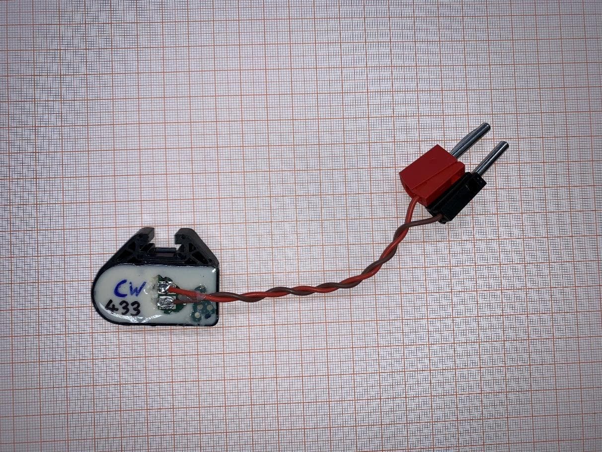
OYGTSSRE4AR
Jul 18, 2022TPMS Sensor S5.32 433 MHz
Equipment Class
DSC - Part 15 Security/Remote Control Transmitter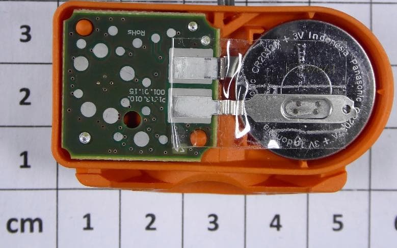
OYGTMSS5A2
Aug 12, 2020TPMS Sensor S5.xG Dual Band
Equipment Class
DSC - Part 15 Security/Remote Control Transmitter
OYGTSSRE4UD
Dec 17, 2014TPMS Sensors of G3.8 Family (433.92 MHz)
Equipment Class
DSC - Part 15 Security/Remote Control Transmitter
OYGTSSRE3UD
Dec 17, 2014Tire Pressure Monitoring System (TPMS)
Equipment Class
DSC - Part 15 Security/Remote Control TransmitterOYGTSSRE4UC
Aug 04, 2014TSSRE4UC
Equipment Class
DSC - Part 15 Security/Remote Control Transmitter