OYIRSS99745BASE
Wireless eSystems, Inc.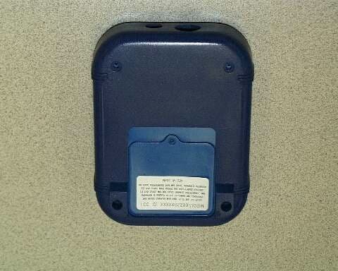
Click to zoom
Application Details
- Equipment Class
- DXX - Part 15 Low Power Communication Device Transmitter
- Date of Grant
- May 07, 2000
- Application Purpose
- Original Equipment
- Date of Application
- Apr 04, 2000
- Frequency Range
- 916.50000000 - 916.50000000
- Company
- Wireless eSystems, Inc.
- Country
- United States
Documents & Files
Document Text
Text extracted from the exhibit documents filed with the FCC. Open a document above to read the original.
Users Manual
FCCUM99725 March 15, 2000 Rev - USERS MANUAL FOR THE RAPID SCORING SYSTEM (RSS) Prepared by: 35 Hill Ave. Fort Walton Beach, FL 32548 (850) 244-2332 Email: www.gomicrosystems.com FCCUM99725 March 15, 2000 Rev - i TABLE OF CONTENTS ParagraphTitlePage 1.0SCOPE1 2.0SYSTEM OVERVIEW1 2.1Base Station Description2 2.2Base Station Set Up2 2.3Remote Interactive Module Description3 2.4Remote Operation5 2.5Battery Charging5 2.6Battery Pack Replacement6 LIST OF FIGURES FigureTitlePage 1RSS Operation1 2RSS Base Station2 3Base Station Display3 4Remote Features4 5Battery Charger6 6Battery Pack Replacement7 LIST OF TABLES TableTitlePage IKeypad Functions4 LIST OF ACRONYMS ACAlternating Current DCDirect Current IDIdentification LCDLiquid Crystal Display PCPersonal Computer RFRadio Frequency RSSRapid Scoring System FCCUM99725 March 15, 2000 Rev - 1 1.0SCOPE . This document provides information on the setup and operation of the Rapid Scoring System (RSS). 2.0System Overview . The RSS consists of a single base station, thirty hand held remote interactive modules and a software package which executes on a personal computer (PC) with a Windows95/98 operating system. The software package will also run on a Macintosh PC. The software package is designed to communicate over a local area network with a server running the software included. The handheld units communicate over a wireless Radio Frequency (RF) link to a base station and utilize rechargeable batteries for “ no wires” operation. Figure 1. illustrates the RSS operation. Figure 1. RSS Operation FCCUM99725 March 15, 2000 Rev - 2 2.1Base Station Description. The base station controls message traffic flow between the PC and the remote units. Note that the base station is a modified version of the remote. An RS232 interface, Alternating Current (AC) wall adapter and a different software package are the only differences between the base station and remote units. The Liquid Crystal Display (LCD) display and keypad are used for diagnostic test and status display on the base station. Figure 2 illustrates the features of the base station. Figure 2. RSS Base Station The base station contains software to collect and distribute information between the remotes and the server. The software has two main functions; first the software manages the radio frequency traffic between the devices and the PC. In addition , this software writes records to and receives records from a local version on the base station The local version is the middleware that takes information and reads/writes data into the master server. 2.2Base Station Set Up . Connect the supplied RS232 cable to the base station circular DIN connector at the bottom of the unit. Connect the other end of the RS232 cable to the serial port of the PC. Connect the direct current (dc) jack on the end of the AC adapter cable into the bottom of the base station. Connect the AC adapter into an AC wall outlet. Press the power button to power the unit on. A second key press to the FCCUM99725 March 15, 2000 Rev - 3 power switch will turn the unit off. The base station will display connection status to the PC RS-232 link and status of the RF links, on the PC display, indicated by a flashing circle for each remote which is responding to the base station. This base unit display is shown in Figure 3. Figure 3. Base Station Display 2.3Remote Interactive Module Description. The remote provides the data entry point for the user of the RSS system. The LCD graphics display, the programmable soft keys and cursor keys allow the user to quickly enter data for transmittal to the server. Figure 4 shows the remote features. Table I below explains the keypad assignments. RSSM Connection: Remote Connections Active: ACTIVE 20 FCCUM99725 March 15, 2000 Rev - 4 Figure 4. Remote Features Table I. Keypad Functions KEYFUNCTION Powerapplies power to unit F1programmable function key F2programmable function key S1-S5programmable soft keys , for answer selection Backspacemove cursor to previous position Flagmark undecided answer up arrowcursor up right arrowcursor right down arrowcursor down left arrowcursor left enterexecute FCCUM99725 March 15, 2000 Rev - 5 To turn the unit on, press the power key. To turn the unit off, press the power key again. Note that during operation the power off function is disabled until the allotted time has elapsed or enabled by the base station. 2.4Remote Operation. The remote units operate in concert with the base station, therefore the base station must be powered on and communication established with the server prior to remote activation. When the remote user turns on the unit the device requests the user to enter his or her personal User Identification (ID) and password using the virtual keyboard display. Upon completion of this information , the ID and password are sent to the server. Upon recognizing the user the server will pass back the options the user is assigned. The user then scrolls the list of options and selects the appropriate one. Once the option is selected, the server sends the selected items to the user. Periodically the Base station will poll the devices and collect information. The information entered by the user will be retrieved and temporarily stored by the base station. In addition, information about the user and the device number the user is operating can be displayed on the personal computer display. When the user has completed the operation, the user will command the remote to deliver any remaining or updated information to the Base Unit. This information will be passed through to the master server for immediate evaluation. Once the information is processed by the master server, the administrator will have the ability to sign on directly to the master server to review results on-line and/or print reports. 2.5Battery Charging. The remote units are shipped with battery packs installed but uncharged. The battery charger is capable of bringing a battery pack from completely discharged to fully ch…
Text truncated - open the document above for the full version.
Block Diagram
RSS Base Unit (Model 120-1) Block Diagram TRANSMIT DATA RECEIVE DATA Crystal 32.768 kHz CPU 18.432MHz Crystal 3.6864 MHz RF XCVR 916.50 MHz Gate Array 1.843 MHz 115.2 kHz
Cover Letter(s)
Joseph J. Luna Micro Systems, Inc. 35 Hill Avenue Ft. Walton Beach, FL 32548 April 10, 2000 FCC Certification: The following is a cover letter requesting confidentiality on selected exhibits for FCC certification on the base unit for the RSS. These items contain proprietary information relative to trade secrets and costly engineering development specific to our organization. Exhibits for confidential status include the schematic diagram and parts list. Please make what ever provisions necessary to ensure these items remain in a confidential status. Respectfully, Joseph J. Luna RF Engineer
External Photos
RSS Base Unit (Model 120-1) External Photographs
ID Label/Location Info
RSS Base Unit (Model 120-1) FCC Identifier
ID Label/Location Info
RSS Base Unit (Model 120-1) External Photographs
ID Label/Location Info
RSS Base Unit (Model 120-1) FCC Identifier
ID Label/Location Info
RSS Base Unit (Model 120-1) FCC Identifier
Internal Photos
RSS Base Unit (Model 120-1) Internal Photographs
Operational Description
FCCOD99725 March 15, 2000 Rev - OPERATING DESCRIPTION FOR THE RAPID SCORING SYSTEM (RSS) Prepared by: 35 Hill Ave. Fort Walton Beach, FL 32548 (850) 244-2332 Email: www.gomicrosystems.com FCCOD99725 March 15, 2000 Rev - 1 The RSS consists of a single base station, thirty hand held remote interactive modules and a software package which executes on a personal computer (PC) with a Windows95/98 operating system. The software package will also run on a Macintosh PC. The software package is designed to communicate over a local area network with a server running the software included. The handheld units communicate over a wireless Radio Frequency (RF) link to a base station and utilize rechargeable batteries for “ no wires” operation. Figure 1. illustrates the RSS operation. Figure 1. RSS Operation The base station contains software to collect and distribute information between the remotes and the server. The software has two main functions; first the software manages the radio frequency traffic between the devices and the PC. In addition , this software writes records to and receives records from a local version on the base station The local version is the middleware that takes information and reads/writes data into the master server. The base station will display connection status to the PC RS-232 link and status of the RF links which are responding to the base station The remote units operate in concert with the base station. When the remote user turns on the unit the device requests the user to enter his or her personal User Identification (ID) and password using the virtual keyboard display. Upon completion of this information , the ID and password are sent to the server. Upon recognizing the user the server will pass back the options the user is assigned. The user then scrolls the list of options and selects the appropriate one. Once the option is selected, the server sends the selected items to the user. FCCOD99725 March 15, 2000 Rev - 2 The remote utilizes NiMH batteries in a 3 cell configuration. The remote is not powered on during charging. While charging the battery charger will illuminate a red LED. When charging is complete the green LED will illuminate and the red LED will extinguish.
Test Report
7800 Highway 20 West Huntsville, Alabama 35806 Phone (256) 837-4411 Fax (256) 830-2109 !mw.wlelabs.com TEST REPORT REPORT NO.: 43957-o 1 WYLE JOB NO.: 43957 CLIENT P.O. NO.: 00-0247 CONTRACT: N/A TOTAL PAGES (INCLUDING COVER): 22 DATE: 8 h&l-& 6. 2000 FCC CERTIFICATION TESTING ON MICRO SYSTEMS’ RAPID SCORING SYSTEM For Micro Systems, Inc. 35 Hill Avenue Fort Walton Beach, FL 32548 Attn: Adam Taylor STATE OF ALABAMA COUNTY OF MADISON Jm, being duly sworn, deposes and says: The information contained in this report is the result of complete and carefully conducted testing and is to the besl of his knowledge true and correct in all COPYRIGHT BY VvYLE LABORATORIES. THE RIGHT TO REPRODUCE, COPY, EXHISI THE EXPRESS PRIOR PERMISSION OF WYLE LABORATORIES IS PROHIBITED. TH CONTAINED HEREIN SHALL SE EQUIVALENTTO EXPRESS PRIOR PERMISSION. WI-I-1404. Rev. Feb ‘97 T. E. A Nyle shall have no liability for damages of any kind to person or property, including special or consequential damages, resulting from Wyle’s providing the servtces movered by this report. Mike Moranha, Sr. Test Specialist Date IR OTHERWISE UTILIZE ANY OF THE MATERIAL CONTAINED HEREIN WITHOUT CCEPTANCE OF A PURCHASE ORDER IN CONNECTION WITH THE MATERIAL Page No. 2 Test Report No. 43957-01 1.0INTRODUCTION 1.1 Scope This report documents conformance with the FCC Rules, Part 15, Class A, as listed below, and details the results of the testing performed on Micro Systems’ Rapid Scoring System (RSS) on February 28 and 29, 2000, at Wyle Laboratories’ Huntsville, Alabama, Test Facility. The specimen was received in good condition on February 28, 2000. 1.2Product Description The Rapid Scoring System (RSS) provides schools with a simple system to conduct standardized testing, The student enters their multiple-choice answers into a small hand-held device rather than using a paper answer sheet. The RSS consists of 30 small hand-held devices (remote units), used by the students, and a base unit connected to a PC. The remote units use radio frequencies (RF) to communicate with the base unit. The base unit connects to the PC via an RS-232 connection and receives its power from a plug-in wall transformer. Each remote unit is powered by a rechargeable battery pack. The base unit polls each remote unit periodically to transfer information required for standardized testing. 1.3 Details for Tested System The identifiers for the test specimen, support devices, and cables used in the tested system are: l Test Specimen Item Part No. Serial No. Quantity Base Unit RSS Wyle 001 1 Remote Unit RSS Wyle 0011 l Support Equipment There was no support equipment used during the FCC Part 15 testing. 1.4 Test Methodology All emissions testing was performed according to the procedures in ANSI C63.4-1992. The EUT is subject to the radiated emission limits for a Class A Digital Device per Subpart B, Paragraphs 15.107(b), 15.109(b), 15.209 at an antenna-to-EUT distance of ten meters. Subpart C (Intentional Radiators), Paragraph 15.249 of the FCC Rules and Regulations testing was conducted at an antenna-to-EUT distance of three meters. VVYLE LABORATORIES Huntsville Facility Page No. 3 Test Report No. 43957-01 1.0INTRODUCTION (Continued) 1.5 Test Facility The Open-Area Test Site facility used to collect the data in this report is located on the grounds of Wyle Laboratories’ Huntsville, Alabama Test Facility. This site has been fully described in reports provided to the FCC Reference 3 1040/SIDDS300B3. This test site was tested and meets the requirements of ANSI C63.4-1992. 1.6References lMicro Systems’ purchase Order No. 00-0247 lWyle Laboratories’ Request for Quotation No. 545/002671Xl/DB lANSI C63.4-1992, “Methods of Measurement of Radio Noise From Low-Voltage Electrical and Electronic Equipment in the Range of 9 kHz to 40 GHz” l Code of Federal Regulations (CFR) Title 47, “Telecommunications,” October 1, 1998 lWyle Laboratories’ Quality Assurance Program Manual, Revision 1 . ANSI/NCSL 2540-1, “Calibration Laboratories and Measuring and Test Equipment, General Requirements n lIS0 10012- 1, “Quality Assurance Requirements for Measuring Equipment” lMIL-STD-45662A, *Calibration System Requirements” 1.7 Quality Assurance 1.7.1 Oualitv_.Assurance Prom All work performed on this test program was completed in accordance with Wyle Laboratories’ Quality Assurance Program. The Wyle Laboratories, Huntsville Facility, Quality Management System is registered - in compliance with the ISO- International Quality Standard. Registration has been completed by Quality Management Institute (QMI), a Division of Canadian Standards Association (CSA). WYLE LABORATORIES Huntsville Facility Page No. 4 Test Report No. 43957-01 1.0INTRODUCTION (Continued) 1.7Quality Assurance (Continued) l l 1.7.2 Test Ew Iustrumeuta~ 2.0 PRODUCT LABELING All instrumentation, measuring, and test equipment used in the performance of this test program were calibrated in accordance with Wyle Laboratories’ Quality Assurance Program, which complies with the requirements of ANSVNCSL 2540-1, IS0 10012-1, and Military Specification MIL-STDA5662A. Standards used in performing all calibrations are traceable to the National Institute of Standards and Technology (NIST) by report number and date. When no national standards exist, the standards are traceable to international standards or the basis for calibration is otherwise documented. Appendix C contains a list of the instrumentation, measuring, and test equipment that was used to perform the tests. THE DEVICE COMPLIES WITH PART I5 OF THE FCC RULES OPERATION IS SUBJECT TO THE FOLLOWING TWO CONDITIONS (1)THE DEVICE MAY NOT CAUSE HARMFUL INTERFERENCE AND (2)THE DEVICE MUST ACCEPT ANY INTERFERENCE RECEIVED INCLUDING INTERFERENCE THAT MAY CAUSE UNDESIRED OPERATION , FCC ID XXXXXXX Figure 2.1- FCC ID Label SYSTEM TEST CONFIGURATION Justification WYLE LABORATORIES Huntsville Faclllty The equipment was configured for testing in a typical fashion (as a customer would normally use it). …
Text truncated - open the document above for the full version.
Test Setup Photos
7800 Highway 20 West Huntsville, Alabama 35806 Phone (256) 837-4411 Fax (256) 830-2109 !mw.wlelabs.com TEST REPORT REPORT NO.: 43957-o 1 WYLE JOB NO.: 43957 CLIENT P.O. NO.: 00-0247 CONTRACT: N/A TOTAL PAGES (INCLUDING COVER): 22 DATE: 8 h&l-& 6. 2000 FCC CERTIFICATION TESTING ON MICRO SYSTEMS’ RAPID SCORING SYSTEM For Micro Systems, Inc. 35 Hill Avenue Fort Walton Beach, FL 32548 Attn: Adam Taylor STATE OF ALABAMA COUNTY OF MADISON Jm, being duly sworn, deposes and says: The information contained in this report is the result of complete and carefully conducted testing and is to the besl of his knowledge true and correct in all COPYRIGHT BY VvYLE LABORATORIES. THE RIGHT TO REPRODUCE, COPY, EXHISI THE EXPRESS PRIOR PERMISSION OF WYLE LABORATORIES IS PROHIBITED. TH CONTAINED HEREIN SHALL SE EQUIVALENTTO EXPRESS PRIOR PERMISSION. WI-I-1404. Rev. Feb ‘97 T. E. A Nyle shall have no liability for damages of any kind to person or property, including special or consequential damages, resulting from Wyle’s providing the servtces movered by this report. Mike Moranha, Sr. Test Specialist Date IR OTHERWISE UTILIZE ANY OF THE MATERIAL CONTAINED HEREIN WITHOUT CCEPTANCE OF A PURCHASE ORDER IN CONNECTION WITH THE MATERIAL Page No. 2 Test Report No. 43957-01 1.0INTRODUCTION 1.1 Scope This report documents conformance with the FCC Rules, Part 15, Class A, as listed below, and details the results of the testing performed on Micro Systems’ Rapid Scoring System (RSS) on February 28 and 29, 2000, at Wyle Laboratories’ Huntsville, Alabama, Test Facility. The specimen was received in good condition on February 28, 2000. 1.2Product Description The Rapid Scoring System (RSS) provides schools with a simple system to conduct standardized testing, The student enters their multiple-choice answers into a small hand-held device rather than using a paper answer sheet. The RSS consists of 30 small hand-held devices (remote units), used by the students, and a base unit connected to a PC. The remote units use radio frequencies (RF) to communicate with the base unit. The base unit connects to the PC via an RS-232 connection and receives its power from a plug-in wall transformer. Each remote unit is powered by a rechargeable battery pack. The base unit polls each remote unit periodically to transfer information required for standardized testing. 1.3 Details for Tested System The identifiers for the test specimen, support devices, and cables used in the tested system are: l Test Specimen Item Part No. Serial No. Quantity Base Unit RSS Wyle 001 1 Remote Unit RSS Wyle 0011 l Support Equipment There was no support equipment used during the FCC Part 15 testing. 1.4 Test Methodology All emissions testing was performed according to the procedures in ANSI C63.4-1992. The EUT is subject to the radiated emission limits for a Class A Digital Device per Subpart B, Paragraphs 15.107(b), 15.109(b), 15.209 at an antenna-to-EUT distance of ten meters. Subpart C (Intentional Radiators), Paragraph 15.249 of the FCC Rules and Regulations testing was conducted at an antenna-to-EUT distance of three meters. VVYLE LABORATORIES Huntsville Facility Page No. 3 Test Report No. 43957-01 1.0INTRODUCTION (Continued) 1.5 Test Facility The Open-Area Test Site facility used to collect the data in this report is located on the grounds of Wyle Laboratories’ Huntsville, Alabama Test Facility. This site has been fully described in reports provided to the FCC Reference 3 1040/SIDDS300B3. This test site was tested and meets the requirements of ANSI C63.4-1992. 1.6References lMicro Systems’ purchase Order No. 00-0247 lWyle Laboratories’ Request for Quotation No. 545/002671Xl/DB lANSI C63.4-1992, “Methods of Measurement of Radio Noise From Low-Voltage Electrical and Electronic Equipment in the Range of 9 kHz to 40 GHz” l Code of Federal Regulations (CFR) Title 47, “Telecommunications,” October 1, 1998 lWyle Laboratories’ Quality Assurance Program Manual, Revision 1 . ANSI/NCSL 2540-1, “Calibration Laboratories and Measuring and Test Equipment, General Requirements n lIS0 10012- 1, “Quality Assurance Requirements for Measuring Equipment” lMIL-STD-45662A, *Calibration System Requirements” 1.7 Quality Assurance 1.7.1 Oualitv_.Assurance Prom All work performed on this test program was completed in accordance with Wyle Laboratories’ Quality Assurance Program. The Wyle Laboratories, Huntsville Facility, Quality Management System is registered - in compliance with the ISO- International Quality Standard. Registration has been completed by Quality Management Institute (QMI), a Division of Canadian Standards Association (CSA). WYLE LABORATORIES Huntsville Facility Page No. 4 Test Report No. 43957-01 1.0INTRODUCTION (Continued) 1.7Quality Assurance (Continued) l l 1.7.2 Test Ew Iustrumeuta~ 2.0 PRODUCT LABELING All instrumentation, measuring, and test equipment used in the performance of this test program were calibrated in accordance with Wyle Laboratories’ Quality Assurance Program, which complies with the requirements of ANSVNCSL 2540-1, IS0 10012-1, and Military Specification MIL-STDA5662A. Standards used in performing all calibrations are traceable to the National Institute of Standards and Technology (NIST) by report number and date. When no national standards exist, the standards are traceable to international standards or the basis for calibration is otherwise documented. Appendix C contains a list of the instrumentation, measuring, and test equipment that was used to perform the tests. THE DEVICE COMPLIES WITH PART I5 OF THE FCC RULES OPERATION IS SUBJECT TO THE FOLLOWING TWO CONDITIONS (1)THE DEVICE MAY NOT CAUSE HARMFUL INTERFERENCE AND (2)THE DEVICE MUST ACCEPT ANY INTERFERENCE RECEIVED INCLUDING INTERFERENCE THAT MAY CAUSE UNDESIRED OPERATION , FCC ID XXXXXXX Figure 2.1- FCC ID Label SYSTEM TEST CONFIGURATION Justification WYLE LABORATORIES Huntsville Faclllty The equipment was configured for testing in a typical fashion (as a customer would normally use it). …
Text truncated - open the document above for the full version.
Contact Information
Applicant
Bill Thompson(Operations/Marketing Manager)
Technical Contact
Micro Systems, Inc.Joe J Luna
[email protected](850) 244-2332
35 Hill Avenue · Fort Walton Beach, Florida · United States
Non-Technical Contact
Micro Systems, Inc.Joe J Luna
[email protected](850) 244-2332
Test Firm
Wyle LaboratoriesJoseph Hazeltine
Technical Specifications
| # | Rule Parts | Frequency Range | Power Output |
|---|---|---|---|
| 1 | 15.249 | 916.5 MHz - 916.5 MHz | - |
Other Applications from Wireless eSystems, Inc.
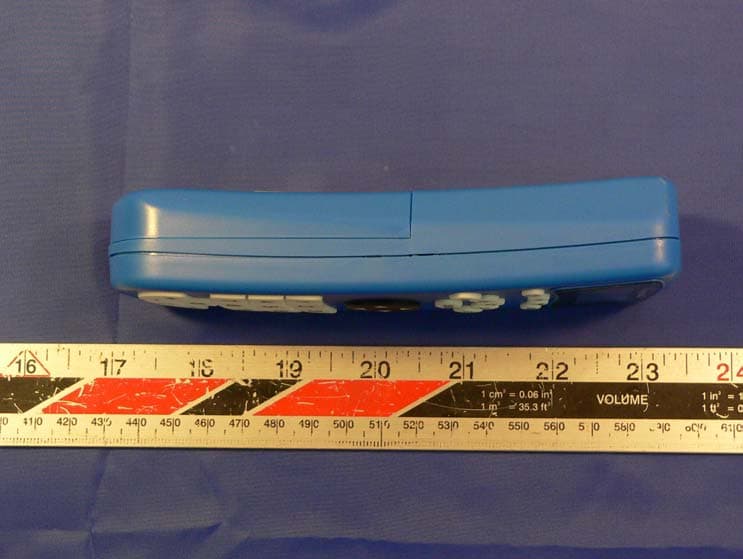
OYILITEREMOTE
Dec 11, 2005Lite Remote
Equipment Class
DXX - Part 15 Low Power Communication Device Transmitter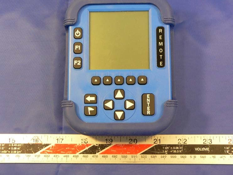
OYITOUCHREMOTE
Dec 11, 2005Touch Remote
Equipment Class
DXX - Part 15 Low Power Communication Device Transmitter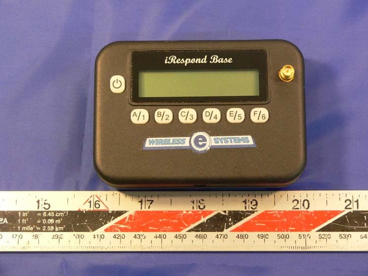
OYILITEBASE
Dec 11, 2005Lite Base
Equipment Class
DXX - Part 15 Low Power Communication Device Transmitter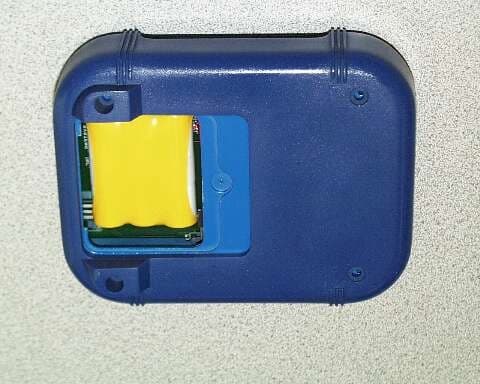
OYIRSS97735SIM
May 07, 2000DXX - Part 15 Low Power Communication Device Transmitter
Equipment Class
DXX - Part 15 Low Power Communication Device Transmitter