OYITOUCHREMOTETouch Remote
Wireless eSystems, Inc.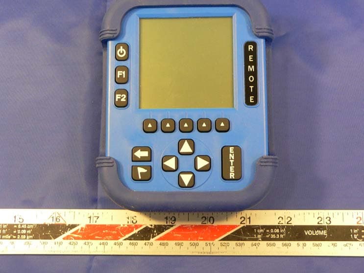
Click to zoom
Application Details
- Equipment Class
- DXX - Part 15 Low Power Communication Device Transmitter
- Date of Grant
- Dec 11, 2005
- Application Purpose
- Original Equipment
- Date of Application
- Dec 11, 2005
- Equipment Note
- Touch Remote
- Frequency Range
- 2432.83170000 - 2435.43170000
- Company
- Wireless eSystems, Inc.
- Country
- United States
Documents & Files
Document Text
Text extracted from the exhibit documents filed with the FCC. Open a document above to read the original.
Users Manual
1 Installation and Setup Installation and Set Up Procedure Installation and setup are quick and easy. All remote units with styluses, the base and antenna, and the USB cable are contained in the carrying case provided. The remote unit battery charging system, power adapter with cords, and charging cables are packed in a separate box within the shipping container. Remove all components and follow the procedures as described and illustrated on the following pages. Setup Procedure Unpack the iRespond Touch system Charge Remote Units Setup the iRespond System Install the iRespond Software (Refer to the separate Quick Guide for Software Installation. Perform Session Setup (Refer to the separate Quick Guide for Session Setup. Remote Unit Battery Pack Charging Each remote unit must be charged prior to use. Unpack the battery charging system from the carton. Included are 8V charging adapters. Connect the AC plug to a wall receptacle. Plug the connector into a remote unit. Each remote will take three to four hours to fully charge. Continue this process until all remotes have been charged. Under normal use, a remote will run for approximately two weeks before recharging is required. 2 iRespond System Setup Linksys USB Hub Setup • Attach USB cable to hub. Locate an available USB port on the computer and attach the other end of the USB cable to this port. Attach the power adapter into the hub. Plug the adapter into a standard electrical outlet. The hub will be automatically detected by the computer and is now ready for use. Base Unit Setup • Screw in the base unit antenna on the top of the unit. To maximize transmission, orient the antenna so that it sticks straight up from the unit. • Using the USB cable provided with the system, connect the end with the mini USB connector to the base unit. Locate an available USB port on the Linksys hub. Connect the other end of the USB cable to the port. • Apply power to the base unit by pressing the Power On/Off button in the upper-left of the unit. • Setup for the base unit is now complete. Remote Unit Setup • Apply power to the remote units by pressing the Power On/Off button in the upper-left of each unit. Take note of the UID number that appears on the bottom of the LCD. This UID number also appears on the back of the remote unit on a separate label below the FCC Label. The iRespond hardware setup is complete. 3 Using the Base and Remote Units Key Function Power On/Off This key, located top-left, turns power on and off the unit. Once a session is established the key is disabled. Pressing this key simultaneously with the up-arrow cursor key will force a remote unit to power off. F1 Function This multipurpose key is used in combination with other keys. Also used to save settings in Configuration Mode. F2 Function The user may use this key to activate the soft keys in a session. The F2 key may also be used to access the Configure and Diagnostics screen. Backspace This key is useful for editing a User ID, a password, or a fill-in response. The Backspace key will erase the last character entered. Flag This key allows the user to mark items for later review in a session. Cursors These keys are used to scroll, navigate and highlight items on the LCD. A user may use these keys to scroll through the question when it is displayed on the LCD. If a remote unit fails to respond to the Power On/Off key, press the up-arrow and the Power On/Off keys simultaneously to force the unit to power off. Enter This key submits the user's input to the base unit for recording or scoring. Soft Keys A user will use these keys to select responses in a session. The Soft Keys are an alternative to selecting responses directly on the touch panel with the stylus. 4 5 Software Installation and Setup System Requirements The iRespond System runs on customer supplied Windows TM -based desktop PCs and laptops. Please verify system compliance before proceeding. The Windows TM -based system requirements: • 400 MHz or higher Pentium II processor • Windows TM 95/98/ME/2000/NT/XP • CD ROM drive • 1 free USB port • 10 MB available disk space • 128 MB RAM Installation and Set Up Procedure Software installation and setup is quick and easy. Locate the iRespond installation CD shipped with the system, and then follow the procedures as described. Procedure: Install the software, Set up the software to run sessions; ♦ Log In and Account Administration ♦ Set Up your Class Rosters ♦ Set Up your Test Banks ♦ Set Up your Remote Units Installation To ensure compatibility, please review the system requirements before installing the software, and then follow the steps below. • Insert the iRespond software installation disc in your CD-ROM drive. • The iRespond Software will automatically launch the installation program. During this process, be sure to answer the items that appear on the screen. • If your computer is not configured to auto-start, select Run from the Start Menu and browse the installation CD for "Setup.exe." Select that file and click OK to start the installation procedure. Sun's Java TM JRE file system is required to run the iRespond software. If the JRE files are not already installed on your computer, setup will automatically load the requisite files. 6 Introduction After installing the software, it is necessary for you to set up user accounts, enter your class rosters, enter your test banks, and set up the remote units before a session can be started. This guide is a step-by-step procedure through those set up dialogs. Toolbar menu selection names and dialog names described in this guide are shown in green. Text entries and toolbar button clicks required by you are shown in bright blue. Log In and Account Administration Launch the iRespond software and the iRespond Login dialog appears. This dialog prompts you for your user name and password. First-time log in is done as administrator. Enter the default user name admin, and the default password changeme, and click the Login button. S…
Text truncated - open the document above for the full version.
Block Diagram
26.00MHz crystal CC2500 RF Transceiver LH75410 ARM Micorocontroller 15 Key Keypad 160 X 160 Graphic LCD display LDO voltage regulator 14.7456 MHz crystal SPI Port 3 Cell NiMH Battery Pack +3.3V Power FRACTUS chip antenna AY07730 Touch remote Block Diagram 1 MB Flash Memory 0.5 MB Static RAM Memory LCD Bias generator
External Photos
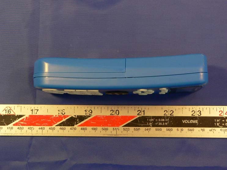
Wireless eSystems, Inc. FCC ID: OYITOUCHREMOTE Report # R0511141Exhibits FCC Part 15.249 Test Report EXHIBIT C - EUT PHOTOGRAPHS EUT Front View EUT Rear View Wireless eSystems, Inc. FCC ID: OYITOUCHREMOTE Report # R0511141Exhibits FCC Part 15.249 Test Report EUT Side View
ID Label/Location Info
EXHIBIT A - FCC ID LABEL INFORMATION Proposed FCC ID Label Specifications: Text is black or white in color and is left justified. Labels are silk-screened and shall be “permanently affixed” at a conspicuous location on the EUT. Proposed Label Location on EUT Bottom view of EUT / Proposed Label location FCC ID: OYITOUCHREMOTE This device complies with Part 15 of the FCC Rules. Operation is subject to the following two conditions: (1) this device may not cause harmful interference, and (2) this device must accept any interference received,
Internal Photos
Wireless eSystems, Inc. FCC ID: OYITOUCHREMOTE Report # R0511141Exhibits FCC Part 15.249 Test Report Cover Off View Component View Wireless eSystems, Inc. FCC ID: OYITOUCHREMOTE Report # R0511141Exhibits FCC Part 15.249 Test Report Solder View Power Supply Front View Wireless eSystems, Inc. FCC ID: OYITOUCHREMOTE Report # R0511141Exhibits FCC Part 15.249 Test Report Power Supply Back View
Test Report
Note: The test report is specially limited to the above company and this particular sample only. It may not be duplicated without prior written consent of Bay Area Compliance Laboratory Corporation. This report must not be used by the client to claim product certification, approval, or endorsement by NVLAP, NIST or any agency of the US Government. FCC PART 15.249 EMI MEASUREMENT AND TEST REPORT For Wireless eSystems, Inc. 65 Hill Ave. Fort Walton Beach, Florida 32548 FCC ID: OYITOUCHREMOTE This Report Concerns: Original Report Equipment Type: Touch Remote Test Engineer: James Ma Report No.: R0511141 Report Date: 2005-12-01 Reviewed By: Snell Leong / Prepared By: Bay Area Compliance Laboratory Corporation 230 Commercial Street Sunnyvale, CA 94085 Tel (408) 732-9162 Fax (408) 732-9164 Wireless eSystems, Inc. FCC ID: OYITOUCHREMOTE Report # R0511141Rpt Page 2 of 16 FCC Part 15.249 Test Report TABLE OF CONTENTS GENERAL INFORMATION.......................................................................................................................................3 PRODUCT DESCRIPTION FOR EQUIPMENT UNDER TEST (EUT) ....................................................................................3 OBJECTIVE...................................................................................................................................................................3 RELATED SUBMITTAL(S)/GRANT(S).............................................................................................................................3 TEST METHODOLOGY..................................................................................................................................................3 TEST FACILITY.............................................................................................................................................................3 SYSTEM TEST CONFIGURATION ..........................................................................................................................5 JUSTIFICATION.............................................................................................................................................................5 SCHEMATICS AND BLOCK DIAGRAM............................................................................................................................5 EQUIPMENT MODIFICATIONS.......................................................................................................................................5 TEST SETUP CONFIGURATION......................................................................................................................................6 TEST SETUP BLOCK DIAGRAM.....................................................................................................................................6 SUMMARY OF TEST RESULTS ...............................................................................................................................7 §15.203 - ANTENNA REQUIREMENT......................................................................................................................8 STANDARD APPLICABLE..............................................................................................................................................8 ANTENNA CONNECTED CONSTRUCTION......................................................................................................................8 § 15.207 (A) - CONDUCTED EMISSIONS TEST DATA .........................................................................................9 MEASUREMENT UNCERTAINTY....................................................................................................................................9 EUT SETUP..................................................................................................................................................................9 RECEIVER SETUP..........................................................................................................................................................9 TEST EQUIPMENT LIST AND DETAILS...........................................................................................................................9 TEST PROCEDURE........................................................................................................................................................9 ENVIRONMENTAL CONDITIONS....................................................................................................................................9 SUMMARY OF TEST RESULTS.....................................................................................................................................10 CONDUCTED EMISSIONS TEST DATA.........................................................................................................................10 PLOT OF CONDUCTED EMISSIONS TEST DATA...........................................................................................................10 §15.205, §15.209 (A), §15.249 (A) - RADIATED EMISSION DATA......................................................................13 APPLICABLE STANDARD............................................................................................................................................13 MEASUREMENT UNCERTAINTY..................................................................................................................................13 EUT SETUP................................................................................................................................................................13 RECEIVER SETUP........................................................................................................................................................14 TEST EQUIPMENT LIST AND DETAILS.........................................................................................................................14 ENVIRONMENTAL CONDITIONS....…
Text truncated - open the document above for the full version.
Test Setup Photos
Wireless eSystems, Inc. FCC ID: OYITOUCHREMOTE Report # R0511141Exhibits FCC Part 15.249 Test Report EXHIBIT B - TEST SETUP PHOTOGRAPHS Conducted Emission – Front View Conducted Emission – Rear View Wireless eSystems, Inc. FCC ID: OYITOUCHREMOTE Report # R0511141Exhibits FCC Part 15.249 Test Report Radiated Emission – Front View Radiated Emission – Rear View
Contact Information
Applicant
Bill Thompson(Operations/Marketing Manager)
Test Firm
Bay Area Compliance LaboratoryJohn Chan
Technical Specifications
| # | Rule Parts | Frequency Range | Power Output |
|---|---|---|---|
| 1 | 15C | 2.43 GHz - 2.44 GHz | - |
Other Applications from Wireless eSystems, Inc.
OYILITEREMOTE
Dec 11, 2005Lite Remote
Equipment Class
DXX - Part 15 Low Power Communication Device Transmitter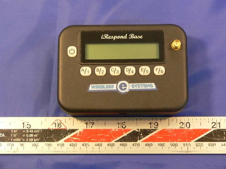
OYILITEBASE
Dec 11, 2005Lite Base
Equipment Class
DXX - Part 15 Low Power Communication Device Transmitter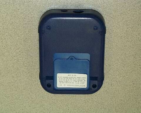
OYIRSS99745BASE
May 07, 2000DXX - Part 15 Low Power Communication Device Transmitter
Equipment Class
DXX - Part 15 Low Power Communication Device Transmitter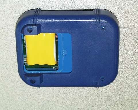
OYIRSS97735SIM
May 07, 2000DXX - Part 15 Low Power Communication Device Transmitter
Equipment Class
DXX - Part 15 Low Power Communication Device Transmitter