OZ9USTC-TED-0003RTU Mobile Transmit Endpoint Device
U. S. Telemetry Corporation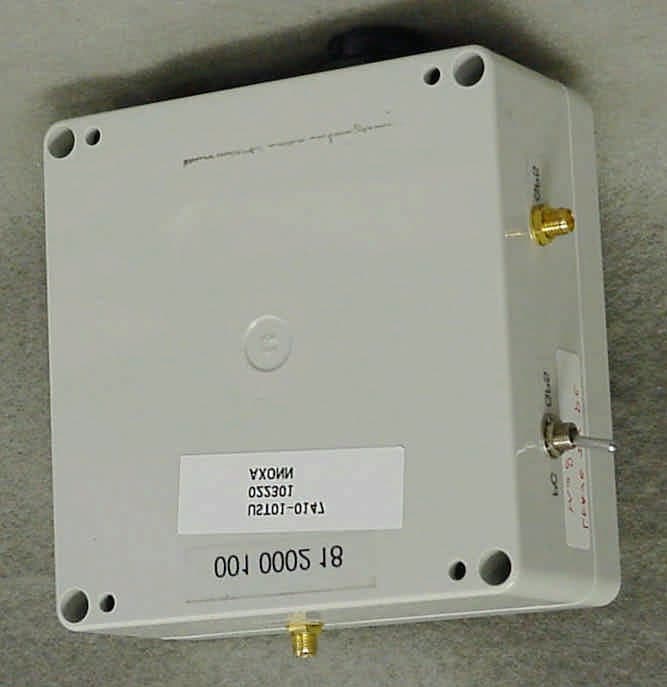
Click to zoom
Application Details
- Equipment Class
- TNB - Licensed Non-Broadcast Station Transmitter
- Date of Grant
- Apr 02, 2001
- Application Purpose
- Original Equipment
- Date of Application
- Apr 02, 2001
- Equipment Note
- RTU Mobile Transmit Endpoint Device
- Frequency Range
- 218.02500000 - 218.97500000
- Company
- U. S. Telemetry Corporation
- Country
- United States
Documents & Files
Document Text
Text extracted from the exhibit documents filed with the FCC. Open a document above to read the original.
Users Manual
Axonn Corporation U.S. Telemetry Mobile Transmit Endpoint Device Users Manual RF Transmitter Installation Instructions The USTC Mobile TED transmitter should only be installed by qualified service personnel. The transmitter detects transmitted GPS signals and other data signals from the external binary inputs and broadcasts that data to the system's CTS sites. MOUNTING LOCATION The USTC TED Transmitter is an RTU as defined by the FCC. The transmitter housing will normally be installed in the trunk or passenger section of a vehicle. The GPS receive-only antenna and the MTED transmit-only antenna shall be mounted external to the vehicle. The omnidirectional transmit- only antenna shall be mounted in the center of the vehicle roof or trunk. The purpose for the location of the transmit-only antenna is two-fold - it 1) insures compliance with FCC exposure requirements and 2) improves the RF radiating characteristics of the transmit-only antenna. The GPS receive-only antenna should be mounted at least 30” away from the transmit antenna. INSTALLATION INSTRUCTIONS 1. Mount the antennas and transmitter housing. Insure that these devices are securely in place. The location of these devices should conform to the above paragraph. 2. Connect the antenna to the proper antenna connector. Note that an improper connection could damage either of the antenna, the MTED, or all three devices. 3. The unit will come pre-programmed with Transmitter ID. There will be field programming of the unit for other parameters. CAUTION: This device is required to comply with FCC RF exposure requirements for mobile transmitting devices. A separation of 20 cm (8 inches) or more must be maintained between the transmit antenna and all persons during device operations to satisfy RF exposure compliance. TESTING THE TRANSMITTER Following system installation, system testing is mandatory. This should be performed by locating the TED in its final location and powering up the unit. On initial power-up, the TED will send out RF messages every 4 seconds or more depending on programming. This will establish communications with the CTS receiver and the information collected will then be used to judge system performance ! FCC NOTICE The USTC TED transmitter generates and uses radio frequency energy. If not installed and used in accordance with the manufacturer's instructions, it may cause interference to radio and television reception. The transmitter has been tested and found to comply with the specifications in Part 95 of the FCC Rules. If this equipment causes interference to radio or television reception - which can be determined by turning the equipment on and off - the installer is encouraged to correct the interference by one or more of the following measures: 1) Reorient the antenna of the radio/television. 2) Connect the AC transformer to a different outlet so the TED and radio/television are on different branch circuits. 3) Relocate the TED with respect to the radio/television. If necessary, the installer should consult an experienced radio/television technician for additional suggestions, or send for the "Interference Handbook" prepared by the Federal Communications Commission. This booklet is available from the U.S. Government Printing Office, Washington, D.C., 20402, stock number 004-000-00450-7. CAUTION: Axonn Corporation does not support field changes or modifications to any of the Axonn Corporation RF equipment unless they are specifically covered in this manual. All adjustments must be made at the factory under the specific guidelines set forth in our manufacturing processes. Any modification to the equipment could void the user's authority to operate the equipment and render the equipment in violation of FCC Part 95. This device complies with Part 95 of the FCC Rules. Operation is subject to the following two conditions: (1) this device may not cause harmful interference, and (2) this device must accept any interference received, including interference that may cause undesired operation. LIMITED WARRANTY THERE ARE NOT WARRANTIES, EXPRESS OR IMPLIED, OF MERCHANTABILITY OR FITNESS FOR A PARTICULAR PURPOSE OR OTHERWISE, WHICH EXTEND BEYOND THE DESCRIPTION ON THE FACE HEREOF. In no case shall Seller be liable to anyone for any consequential or incidental damages for breach of this or any other warranty, express or implied, or upon any other basis of liability whatsoever, even if the loss or damage is caused by Seller's own negligence or fault.
Cover Letter(s)
FCC ID: OZ9USTC-TED-0003
Cover Letter(s)
FCC ID: OZ9USTC-TED-0003
External Photos
FCC ID: OZ9USTC-TED-0003 SECTION 5 PHOTOGRAPHS FCC ID: OZ9USTC-TED-0003 PHOTOS OF THE TESTED EUT The following photos are attached: Photo 1.EUT, Front View Photo 2.EUT, Rear View Photo 3.EUT, Bottom View Showing Interface Connector Photo 4.EUT, Top View Showing Transmit Antenna Port Photo 5.EUT, Side View Showing GPS RX Antenna Port Photo 6.EUT, Internal View Cover Removed Photo 7.EUT, Top View of +9V Regulator Board Photo 8.EUT, Bottom View of +9V Regulator Board Photo 9.EUT, Top View of GPS Receiver Photo 10.EUT, Top View of GPS Receiver (Shield Removed) Photo 11.EUT, Bottom View of GPS Receiver Photo 12.EUT, Top View of GPS Interface Board Photo 13.EUT, Bottom View of GPS Interface Board Photo 14.EUT, Transmitter and Battery Board Assembly Photo 15.EUT, Top View of Battery Assembly Board, Transmitter Removed Photo 16.EUT, Bottom View of Battery Assembly Board Photo 17.EUT, Top View of Transmitter Board Photo 18.EUT, Top View of Transmitter Board, Shields Removed Photo 19.EUT, Bottom View of Transmitter Board Photo 20. Antenna Connection Board Photo 21.EUT, View of Transmit Antenna Photo 22.EUT, View of GPS Receive Antenna FCC ID: OZ9USTC-TED-0003 Photo 1.EUT, Front View FCC ID: OZ9USTC-TED-0003 Photo 2.EUT, Rear View FCC ID: OZ9USTC-TED-0003 Photo 3.EUT, Bottom View Showing Interface Connector FCC ID: OZ9USTC-TED-0003 Photo 4.EUT, Top View Showing Transmit Antenna Port FCC ID: OZ9USTC-TED-0003 Photo 5.EUT, Side View Showing GPS RX Antenna Port
ID Label/Location Info
FCC ID: OZ9USTC-TED-0003 SECTION 3 LABELING INFORMATION FCC ID: OZ9USTC-TED-0003
Internal Photos
FCC ID: OZ9USTC-TED-0003 Photo 6.EUT, Internal View Cover Removed FCC ID: OZ9USTC-TED-0003 Photo 7.EUT, Top View of +9V Regulator Board FCC ID: OZ9USTC-TED-0003 Photo 8.EUT, Bottom View of +9V Regulator Board FCC ID: OZ9USTC-TED-0003 Photo 9.EUT, Top View of GPS Receiver FCC ID: OZ9USTC-TED-0003 Photo 10.EUT, Top View of GPS Receiver (Shield Removed) FCC ID: OZ9USTC-TED-0003 Photo 11.EUT, Bottom View of GPS Receiver FCC ID: OZ9USTC-TED-0003 Photo 12.EUT, Top View of GPS Interface Board FCC ID: OZ9USTC-TED-0003 Photo 13.EUT, Bottom View of GPS Interface Board FCC ID: OZ9USTC-TED-0003 Photo 14.EUT, Transmitter and Battery Board Assembly FCC ID: OZ9USTC-TED-0003 Photo 15.EUT, Top View of Battery Assembly Board, Transmitter Removed FCC ID: OZ9USTC-TED-0003 Photo 16.EUT, Bottom View of Battery Assembly Board FCC ID: OZ9USTC-TED-0003 Photo 17.EUT, Top View of Transmitter Board FCC ID: OZ9USTC-TED-0003 Photo 18.EUT, Top View of Transmitter Board, Shields Removed FCC ID: OZ9USTC-TED-0003 Photo 19.EUT, Bottom View of Transmitter Board FCC ID: OZ9USTC-TED-0003 Photo 20. Antenna Connection Board FCC ID: OZ9USTC-TED-0003 Photo 21.EUT, View of Transmit Antenna FCC ID: OZ9USTC-TED-0003 Photo 22.EUT, View of GPS Receive Antenna
Contact Information
Applicant
Donald M. Clarke(President)
225 761-9501Fax: 225 408-3091
Technical Contact
U.S. Technologies, IncTimothy R Johnson
[email protected]770 740 0717
3505 Francis Circle · Alpharetta, Georgia · United States
Technical Specifications
| # | Rule Parts | Frequency Range | Power Output | Emission | Tolerance |
|---|---|---|---|---|---|
| 1 | 95F | 218.025 MHz - 218.975 MHz | 1.24 W | 30K2F2D | 20.0000000000 ppm |
Other Applications from U. S. Telemetry Corporation
OZ9USTC-TED-0004
Oct 16, 2001Response Transmitter Unit
Equipment Class
TNB - Licensed Non-Broadcast Station Transmitter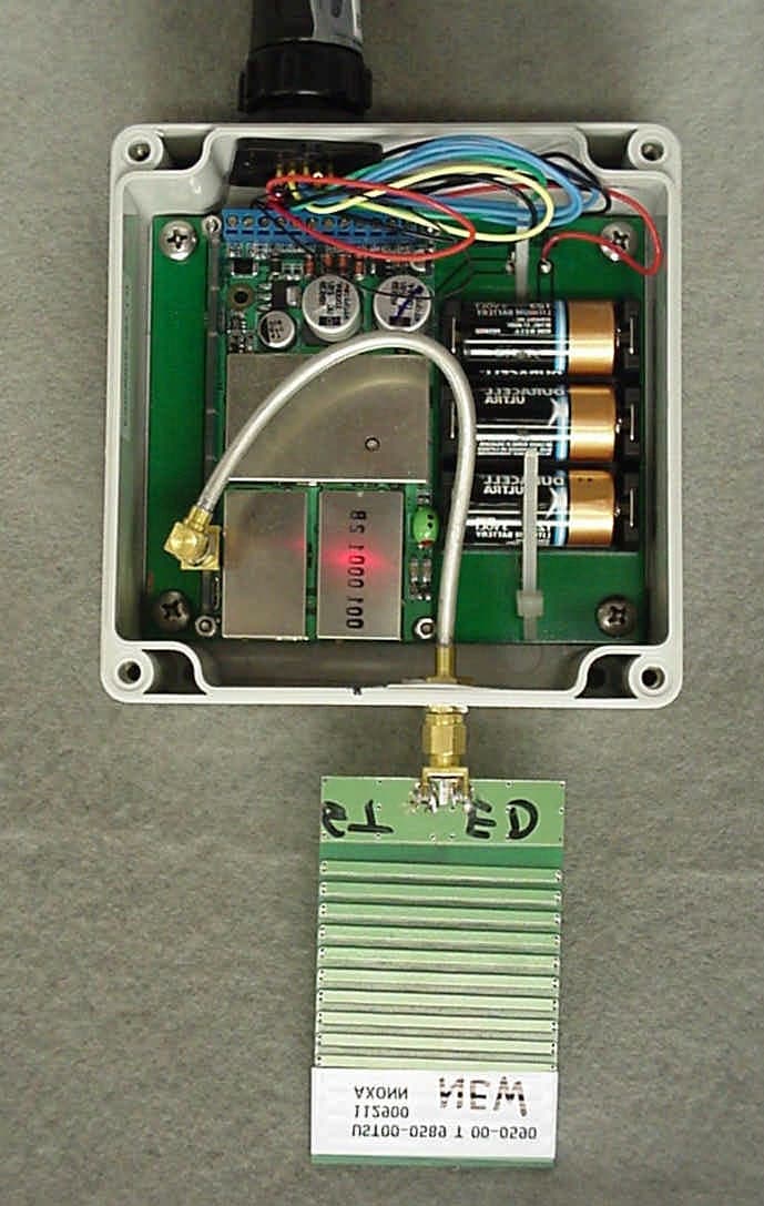
OZ9USTC-TED-0002E
Mar 13, 2001RTU Meter Telemetry Device
Equipment Class
TNB - Licensed Non-Broadcast Station Transmitter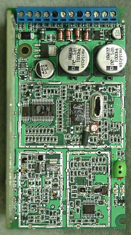
OZ9USTC-TED-0002
Mar 11, 2001RTU Meter Telemetry Device
Equipment Class
TNB - Licensed Non-Broadcast Station Transmitter
OZ9USTC-TED-002I
Mar 07, 2001RTU Meter Telemetry Device
Equipment Class
TNB - Licensed Non-Broadcast Station Transmitter
OZ9USTC-TED-0001
Jun 12, 2000Response Transmitter Unit (RTU) under Part 95
Equipment Class
TNB - Licensed Non-Broadcast Station Transmitter