OZGV740-BA50C2ARFID Reader Transmitter
Omron Corporation, RFID Business Development Department
Click to zoom
Application Details
- Equipment Class
- DSS - Part 15 Spread Spectrum Transmitter
- Date of Grant
- Jan 12, 2006
- Application Purpose
- Original Equipment
- Date of Application
- Jan 12, 2006
- Equipment Note
- RFID Reader Transmitter
- Frequency Range
- 902.72600000 - 927.32200000
- Country
- Japan
Documents & Files
Document Text
Text extracted from the exhibit documents filed with the FCC. Open a document above to read the original.
Users Manual
V740 RFID READER/WRITER, ANTENNA 2005-09, REV.01 OPERATION MANUAL 1 of 56 ©OMRON CORPORATION 2005 V740-series UHF RFID System Operation Manual V740-BA50C22A-US (Bi-static Reader/Writer) V740-HS02CA (Circular Antenna) V740-HS02C (Circular Antenna) Cat.No. RFM – XXX – XX Reader/Writer Antenna V740 RFID READER/WRITER, ANTENNA 2005-09, REV.01 OPERATION MANUAL 2 of 56 ©OMRON CORPORATION 2005 PRECAUTIONS Please read and understand this manual before using the products. Please consult your OMRON representative if you have any question or comments. WARRANTY: OMRON’S EXCLUSIVE WARRANTY IS THAT THE PRODUCTS ARE FREE FROM DEFECTS IN MATERIALS AND WORKMANSHIP FOR A PERIOD OF ONE YEAR (OR OTHER PERIOD IF SPECIFIED) FROM DATE OF SALE BY OMRON. OMRON MAKES NO WARRANTY OR REPRESENTATION, EXPRESS OR IMPLIED, REGARDING NON-INFRINGEMENT, MERCHANTABILITY, OR FITNESS FOR PARTICULAR PURPOSE OF THE PRODUCTS. ANY BUYER OR USER ACKNOWLEDGES THAT THE BUYER OR USER ALONE HAS DETERMINED THAT THE PRODUCTS WILL SUITABLY MEET THE PREQUIREMENTS OF THEIR INTENDED USE. OMRON DISCLAIMS ALL OTHER WARRANTIES, EXPRESS OR IMPLIED. LIMITATIONS OF LIABILITY: OMRON SHALL NOT BE RESPONSIBLE FOR SPECIAL, INDIRECT, OR CONSEQUENTIAL DAMAGES, LOSS OF PROFITS OR COMMERCIAL LOSS IN ANY WAY CONNECTED WITH THE PRODUCTS, WHETHER SUCH CLAIM IS BASED ON CONTRACT, WARRANTY, NEGLIGENCE, OR STRICT LIABILITY. IN NO EVENT SHALL THE RESPONSIBILITY OF OMRON FOR ANY ACT EXCEED THE INDIVIDUAL PRICE OF THE PRODUCT ON WHICH LIABILITY IS ASSERTED. IN NO EVENT SHALL OMRON BE RESPONSIBLE FOR WARRANTY, REPAIR, OR OTHER CLAIMS REGARDING THE PRODUCTS UNLESS OMRON'S ANALYSIS CONFIRMS THAT THE PRODUCTS WERE PROPERLY HANDLED, STORED, INSTALLED, AND MAINTAINED AND NOT SUBJECT TO CONTAMINATION, ABUSE, MISUSE, OR INAPPROPRIATE MODIFICATION OR REPAIR. SUITABLITY FOR USE : OMRON SHALL NOT BE RESPONSIBLE FOR CONFORMITY WITH ANY STANDARDS, CODES, OR REGULATIONS THAT APPLY TO THE COMBINATION OF THE PRODUCTS IN THE CUSTOMER'S APPLICATION OR USE OF THE PRODUCT. TAKE ALL NECESSARY STEPS TO DETERMINE THE SUITABILITY OF THE PRODUCT FOR THE SYSTEMS, MACHINES, AND EQUIPMENT WITH WHICH IT WILL BE USED. KNOW AND OBSERVE ALL PROHIBITIONS OF USE APPLICABLE TO THIS PRODUCT. NEVER USE THE PRODUCTS FOR AN APPLICATION INVOLVING SERIOUS RISK TO LIFE OR PROPERTY WITHOUT ENSURING THAT THE SYSTEM AS A WHOLE HAS BEEN DESIGNED TO ADDRESS THE RISKS, AND THAT THE OMRON PRODUCT IS PROPERLY RATED AND INSTALLED FOR THE INTENDED USE WITHIN THE OVERALL EQUIPMENT OR SYSTEM. CHANGE IN SPECIFICATIONS : PRODUCT SPECIFICATIONS AND ACCESSORIES MAY BE CHANGED AT ANY TIME BASED ON IMPROVEMENTS AND OTHER REASONS. CONSULT WITH YOUR OMORN REPRESENTATIVE AT ANY TIME TO CONFIRM ACTUAL SPECIFICATIONS OF PURCHASED PRODUCT. Regulatory Compliance EMC ................................................................... 47 CFR, Part 15 ................................................................................RSS210 Safety ........................................................................... UL 60950 .................................................... Can/CSA C22.2 No 60950 FCC COMPLIANCE: This equipment complies with Part 15 of the FCC rules for intentional radiators and Class A digital devices when installed and used in accordance with the operation manual. Following these rules provides reasonable protection against harmful interference from equipment operated in a commercial area. This equipment should not be installed in a residential area as it can radiate radio frequency energy that could interfere with radio communications, a situation the user would have to fix at their own expense. EQUIPMENT MODIFICATION CAUTION: Equipment changes or modifications not expressly approved by OMRON Corporation, the party responsible for FCC compliance, could void the user's authority to operate the equipment and could create a hazardous condition. IMPORTANT USER INFORMATION: In order to comply with FCC/IC requirements for RF exposure safety, a separation distance of at least 23 cm (9.1in) needs to be maintained between the radiating elements of the antenna and the bodies of nearby persons. This transmitter must not be co-located or operated in conjunction with any other antenna or transmitter. ©Copyright OMRON Corporation 2005. All rights reserved. This document is protected by copyright and is intended solely for use in conjunction with the product. Notify your OMRON representative before copying or reproducing this document in any manner, for any other purpose. Warranty, Limitations of Liability Application Precautions, Change in Specifications Declarations V740 RFID READER/WRITER, ANTENNA 2005-09, REV.01 OPERATION MANUAL 3 of 56 ©OMRON CORPORATION 2005 Safety Precautions This chapter provides important information for the safe use of this product. Ensure to read the information carefully before use. IN THE SAFETY PRECAUTIONS BELOW, SEVERITY IS CATEGORIZED AS EITHER ”WARNING” OR “CAUTION”. Warning Indicates a potentially hazardous situation which, if not avoided, could result in minor or moderate injury, or may result in serious injury or death. Additionally there may be significant property damage. Caution Indicates a potentially hazardous situation which, if not avoided, may result in minor or moderate injury, or property damage. Property damage refers to extended damage caused to house/household goods or livestock/pets. ●Description of Symbols Prohibition Indicates an action or activity not permitted. Observe strictly Indicates the need to ensure the safe use of the product. Ensure to establish a solid grounding A label indicating that a device with a grounding terminal should always be grounded. Electric shock hazard A notification that alerts the possibility of electric shock under certain conditions. Do not disassemble A notification that prohibits disassembly when injuries caused by electric shocks may result. Please ensure that all cautions and prohibitions are adhered to, since non-compliance may lead …
Text truncated - open the document above for the full version.
External Photos
AntennaModelV740-HS02CA Photos ExternalPhotos Chassis Top Chassis Bottom Chassis Front Chassis Back Chassis Side Internal Photos Antenna Model:V740-HS02C Photos External Photos Chassis Top Chassis Bottom Chassis Back Chassis Front Chassis Side
External Photos
Reader/Writer Model: V740-BA50C22A-US External Photos Chassis Top Chassis Bottom Chassis Front Chassis Back Chassis Side
ID Label/Location Info
FCC LABEL FCC LABEL
Internal Photos
End
Internal Photos
Chassis Bottom Board in Chassis Chassis Inside Digital Board Top Digital Board Bottom Analog Board Top Analog Board Bottom
Test Report
Test report No. : 26AE0013-HO-1a Page : 2 of 42 Issued date : November 24, 2005 Revised : December 28, 2005 FCC ID : OZGV740-BA50C2A UL Apex Co., Ltd. Head Office EMC Lab. 4383-326 Asama-cho, Ise-shi, Mie-ken 516-0021 JAPAN Telephone : +81 596 24 8116 Facsimile : +81 596 24 8124 MF060b(01.06.05) CONTENTS PAGE SECTION 1: Client information .................................................................................................................... 3 SECTION 2: Equipment under test (E.U.T.)................................................................................................. 3 SECTION 3: Test specification, procedures & results ................................................................................ 5 SECTION 4: Operation of E.U.T. during testing ......................................................................................... 8 SECTION 5: Conducted Emission............................................................................................................... 10 SECTION 6: Spurious Emission.................................................................................................................. 11 SECTION 7: 20dB Bandwidth ..................................................................................................................... 12 SECTION 8: Maximum Peak Output Power ............................................................................................. 12 SECTION 9: Carrier Frequency Separation .............................................................................................. 12 SECTION 10: Number of Hopping Frequency .......................................................................................... 12 SECTION 11: Dwell time ............................................................................................................................. 12 APPENDIX 1: Photographs of test setup .................................................................................................... 13 Conducted Emission...............................................................................................................................................13 Spurious Emission (Radiated) ...............................................................................................................................14 APPENDIX 2:Test instruments.............................................................................................................................15 APPENDIX 3: Data of EMI test.................................................................................................................... 16 Conducted Emission...............................................................................................................................................16 Carrier Frequency Separation ..............................................................................................................................20 20dB Bandwidth .....................................................................................................................................................22 Number of Hopping Frequency ............................................................................................................................24 Dwell time ...............................................................................................................................................................25 Maximum Peak Output Power & Variation of Input AC Power .......................................................................27 Radiated Spurious Emission..................................................................................................................................31 Conducted Spurious Emission ..............................................................................................................................37 99% Occupied Bandwidth.....................................................................................................................................42 Test report No. : 26AE0013-HO-1a Page : 3 of 42 Issued date : November 24, 2005 Revised : December 28, 2005 FCC ID : OZGV740-BA50C2A UL Apex Co., Ltd. Head Office EMC Lab. 4383-326 Asama-cho, Ise-shi, Mie-ken 516-0021 JAPAN Telephone : +81 596 24 8116 Facsimile : +81 596 24 8124 MF060b(01.06.05) SECTION 1: Client information Company Name : OMRON Corporation Address : 2-2-1,Nishikusatsu, Kusatsu-city, Shiga-pref., 525-0035 Japan Telephone Number : +81-77-565-5287 Facsimile Number : +81-77-565-5553 Contact Person : Koji Andou SECTION 2: Equipment under test (E.U.T.) 2.1 Identification of E.U.T. Type of Equipment : Radio Identification System (Reader/Writer and Antenna) Model No. : READER/WRITER: V740-BA50C22A-US ANTENNA : V740-HS02CA Serial No. : READER/WRITER: RFP-DS-051104 ANTENNA : RFP-DS-051104 Rating : AC100 to 240V, 2.3A 50/60Hz(with attached AC Adaptor) DC OUT 24V Country of Manufacture : JAPAN Receipt Date of Sample : November 4, 2005 Condition of EUT : Production prototype (Not for Sale: This sample is equivalent to mass-produced items.) 2.2 Product Description Model No: V740-BA50C22A-US and V740-HS02CA (referred to as the EUT in this report) is the Radio Identification System (Reader/Writer and Antenna). The antenna, V740-HS02CA has a variant model: V740-HS02C. The difference between two models is the use of lead- free soldering. The lead-free soldering is used for V740-HS02CA, but not for V740-HS02C. There is no difference in the hardware between two antennas. Frequency Hopping System (RF-ID) Equipment Type Transceiver Frequency Range 902.726MHz – 927.322MHz Bandwidth and Channel specing 24.8MHz (Hopping on), 581.5kHz (Hopping off) and 500kHz Antenna Type Patch Antenna Antenna Connector Type N-type Antenna Gain +6.0 dBi max ITU Code A1D Type of Modulation Frequency Hopping Frequency of Operation CPU: 266MHz (33.333MHz), PLL: 8.0MHz, 25MHz, 33MHz, 54.24MHz Power Supply AC100 to 240V, 2.3A 50/60Hz (with…
Text truncated - open the document above for the full version.
Test Setup Photos
Test report No. : 26AE0013-HO-1a Page : 13 of 42 Issued date : November 24, 2005 Revised : December 28, 2005 FCC ID : OZGV740-BA50C2A UL Apex Co., Ltd. Head Office EMC Lab. 4383-326 Asama-cho, Ise-shi, Mie-ken 516-0021 JAPAN Telephone : +81 596 24 8116 Facsimile : +81 596 24 8124 MF060b(01.06.05) APPENDIX 1: Photographs of test setup Conducted Emission Front Rear Test report No. : 26AE0013-HO-1a Page : 14 of 42 Issued date : November 24, 2005 Revised : December 28, 2005 FCC ID : OZGV740-BA50C2A UL Apex Co., Ltd. Head Office EMC Lab. 4383-326 Asama-cho, Ise-shi, Mie-ken 516-0021 JAPAN Telephone : +81 596 24 8116 Facsimile : +81 596 24 8124 MF060b(01.06.05) Spurious Emission (Radiated) Front Rear
Contact Information
Applicant
Shinichiro Fukuoka(RFID Business Development Department)
Technical Contact
UL Apex Co., LtdMakoto Kosaka
[email protected]+81-596-24-8116
4383-326 Asama-cho · Ise-shi, Mie-Ken, California · Japan
Non-Technical Contact
UL Apex Co., LtdKanako Sanda
[email protected]+81-596-24-8116
Test Firm
UL Japan, IncMitsuru Fujimura
Technical Specifications
| # | Rule Parts | Frequency Range | Power Output |
|---|---|---|---|
| 1 | 15C | 902.726 MHz - 927.322 MHz | 984.00 mW |
Other Applications from Omron Corporation, RFID Business Development Department
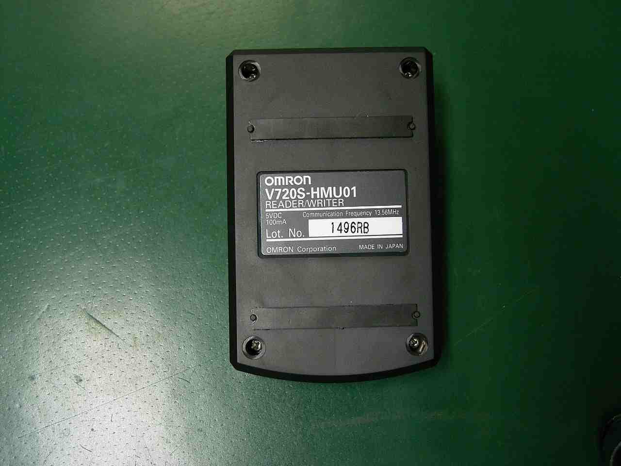
OZGV720SHMU01
Jan 07, 2008RFID Transmitter
Equipment Class
DXX - Part 15 Low Power Communication Device Transmitter
OZGV680-CHXD
Nov 08, 2007RFID Reader/Writer
Equipment Class
DXX - Part 15 Low Power Communication Device Transmitter
OZGV720SBC5D4A-US
Oct 09, 2006RF ID Reader
Equipment Class
DXX - Part 15 Low Power Communication Device Transmitter
OZGV740-BA50CX4
Sep 01, 2005Radio Identification System
Equipment Class
DSS - Part 15 Spread Spectrum Transmitter
OZGV740-BA50CX2
Jan 31, 2005RFID Frequency Hopping Transmitter
Equipment Class
DSS - Part 15 Spread Spectrum Transmitter