OZGV740-BA50CX2RFID Frequency Hopping Transmitter
Omron Corporation, RFID Business Development Department
Click to zoom
Application Details
- Equipment Class
- DSS - Part 15 Spread Spectrum Transmitter
- Date of Grant
- Jan 31, 2005
- Application Purpose
- Original Equipment
- Date of Application
- Jan 31, 2005
- Equipment Note
- RFID Frequency Hopping Transmitter
- Frequency Range
- 902.00000000 - 928.00000000
- Country
- Japan
Documents & Files
Document Text
Text extracted from the exhibit documents filed with the FCC. Open a document above to read the original.
Users Manual
V740 RFID READER NOTE. SPECIFICATIONS SUBJECT TO CHANGE WITHOUT NOTICE. REV. 1.1 OPERATION MANUAL 1 of 27 © OMRON CORPORATION 2004 V740-series RFID Reader/Writer Antenna Operation Manual V740-BA50C02- US 2 Ports - Reader/Writer V740-BA50C22- US 4 Ports – Reader/Writer V740-HS02C Dual Patch Antenna The OMRON V740 RFID Reader/Writer (herein after denoted as Reader) uses RFID (radio frequency identification) technology to read data stored on RFID tags. The Reader operates analogous to an SQL (structured query language) server, providing tag data in response to requests from another application. A separate software application may be used to direct its operation and provide a user interface. The Reader supports UHF (ultra high frequency) antennas, which are available separately. The Reader supports multiple configurations of UHF antenna ports and transfers data to a remote computer over a network connection. Contents V740 RFID Reader ................................. 1 About this Guide..............................................2 Before You Begin ............................................2 Installation Requirements .........................2 Performance Considerations ....................2 Antennas .........................................................4 Antenna Cables ........................................4 Setting the Reader RF Power...................4 Reader Installation ..........................................5 Install the Reader......................................5 Install the Antennas ..................................5 Connect the Reader..................................5 Antenna Connection Options....................6 Reader Configuration ......................................6 Reader Service................................................7 Using the Browser-Based Interface ..........7 Restarting the Reader.............................12 Using Safe Mode ....................................12 Specifications ................................................13 V740 RFID Reader Query Protocol ..... 14 Transport Protocol.........................................14 TCP Connection Setup and Teardown ...14 Event/Query Protocol ....................................14 Client Software Requests/Functionality ..15 General Observations, Commands, and Syntax .....................................................15 Extended RQL Command Structure supported by the V740............................15 Detailed Command Structure .................17 Errors......................................................21 Protocol Specific Functionality and Parameter Settings .................................23 915 MHz EPC Class 1 ............................23 915 MHz EPC Class 0 ............................24 Examples.......................................................26 Example 1 ...............................................26 Example 2 ...............................................26 Example 3 ...............................................26 Declarations ......................................... 27 V740 RFID READER NOTE. SPECIFICATIONS SUBJECT TO CHANGE WITHOUT NOTICE. REV. 1.1 OPERATION MANUAL 2 of 27 © OMRON CORPORATION 2004 About this Guide This installation and usage guide explains how to install the V740 Reader, how to use the browser- based interface, and how to control the Reader remotely. . Use the instructions provided with the antennas to install and service the antennas. Note: Because customer requirements dictate the placement of Reader and antenna components, your OMRON representative will supply this information separately. Before You Begin Installation Requirements • The Reader is shipped with a certified limited power source with a cable length of 1.8m (6ft). • Use only authorized antennas and cables to maintain FCC approval (see page 3). • In order to comply with FCC requirements for RF exposure safety, a separation distance of at least 21 cm (8.3 in) needs to be maintained between the radiating elements of the antenna and the bodies of nearby persons. • Provide strain relief for all Reader connections. • The minimum screw size for mounting the Reader is #12 (M5). Use suitable wall anchors when mounting to drywall or masonry. • An Shielded Ethernet cable must be used to communicate with other devices. • Multiple Readers and antennas can be used in combination to enhance detection at specific locations provided the software application is able to synchronize antenna operation. • Recommended minimum configuration for a computer running an application that interfaces with the V740 Reader: – Pentium® 400 MHz processor – 128MB memory – 10 GB hard drive – Microsoft® Windows® 2000 or Windows XP operating system – Base-T-10/100 Ethernet® port – CD-ROM drive Performance Considerations Reader performance may be affected by external factors including tag variables and environment. Performance tests conducted under typical operating conditions at your site are recommended to help you optimize system performance. Tag Variables There are several variables associated with tags that can affect Reader performance: • Application surface — Some materials interfere with tag performance including metal and moisture. Tags applied to items made from or containing these materials may not perform as expected. • Tag orientation — Reader performance is affected by the orientation of the tag in the antenna field. • Tag model — many tag models are available. Each model has its own performance characteristics. Environment Reader performance may be affected by the following: • Metal surfaces such as desks, filing cabinets, bookshelves, and wastebaskets may enhance or degrade Reader performance. Mount antennas as far as possible from metal surfaces that are adversely affecting system performance. • Devices that operate at 900 MHz, such as cordless phones and wireless LANs, can interfere with Reader performance. These devices may degrade performance of the Reader. The Reader may also adversely affect performance …
Text truncated - open the document above for the full version.
External Photos
OMRON Corporation FCC ID: OZGV740-BA50CX2 Confidential 1/10 Reader/Writer Model : V740-BA50CXX-US Photos External Photos Chassis Top OMRON Corporation FCC ID: OZGV740-BA50CX2 Confidential 2/10 Chassis Bottom OMRON Corporation FCC ID: OZGV740-BA50CX2 Confidential 3/10 Chassis Front OMRON Corporation FCC ID: OZGV740-BA50CX2 Confidential 4/10 Chassis Back OMRON Corporation FCC ID: OZGV740-BA50CX2 Confidential 5/10 Chassis Side OMRON Corporation FCC ID: OZGV740-BA50CX2 Confidential 6/10 Antenna Model : V740-HS02C Photos External Photos Chassis Top OMRON Corporation FCC ID: OZGV740-BA50CX2 Confidential 7/10 Chassis Bottom OMRON Corporation FCC ID: OZGV740-BA50CX2 Confidential 8/10 Chassis Front OMRON Corporation FCC ID: OZGV740-BA50CX2 Confidential 9/10 Chassis Bottom OMRON Corporation FCC ID: OZGV740-BA50CX2 Confidential 10/10 Chassis Side
ID Label/Location Info
Reader/WriterModel:V740-BA50CXX-US Label Design and Location Label Location
Internal Photos
OMRON Corporation FCC ID: OZGV740-BA50CX2 Confidential 1/6 Reader/Writer Model : V740-BA50CXX-US Photos Internal Photos Chassis Top OMRON Corporation FCC ID: OZGV740-BA50CX2 Confidential 2/6 Chassis Bottom OMRON Corporation FCC ID: OZGV740-BA50CX2 Confidential 3/6 Board in Chassis OMRON Corporation FCC ID: OZGV740-BA50CX2 Confidential 4/6 Digital Board top Digital Board Bottom OMRON Corporation FCC ID: OZGV740-BA50CX2 Confidential 5/6 Analog Board Top Analog Board Bottom OMRON Corporation FCC ID: OZGV740-BA50CX2 Confidential 6/6 Antenna Model : V740-HS02C Photos Internal Photos
Test Report
Test report No. : 25EE0130-HO-1 Page : 1 of 35 Issued date : January 12, 2005 FCC ID : OZGV740-BA50CX2 Revised date : January 20, 2005 Revised date : February 1, 2005 UL Apex Co., Ltd. Head Office EMC Lab. 4383-326 Asama-cho, Ise-shi, Mie-ken 516-0021 JAPAN Telephone : +81 596 24 8116 Facsimile : +81 596 24 8124 MF060b(10.04.03) EMI TEST REPORT Test Report No. : 25EE0130-HO-1 Applicant : OMRON Corporation Type of Equipment : RFID System(Reader/Writer and Antenna) Model No. : V740-BA50C22-US and V740-HS02C Test standard : FCC Part 15 Subpart C Section 15.207, Section 15.247 : 2004 FCC ID : OZGV740-BA50CX2 Test Result : Complied 1. This test report shall not be reproduced in full or partial, without the written approval of UL Apex Co., Ltd. 2. The results in this report apply only to the sample tested. 3. This equipment is in compliance with above regulation. We hereby certify that the data contain a true representation of the EMC profile. 4. The test results in this report are traceable to the national or international standards. Date of test: _____________________________ Tested by: ______________________________ Makoto Kosaka EMC Service Approved by : ______________________________ Naoki Sakamoto Group Leader of EMC Service December 20 and 21, 2004 Test report No. : 25EE0130-HO-1 Page : 2 of 35 Issued date : January 12, 2005 FCC ID : OZGV740-BA50CX2 Revised date : January 20, 2005 Revised date : February 1, 2005 UL Apex Co., Ltd. Head Office EMC Lab. 4383-326 Asama-cho, Ise-shi, Mie-ken 516-0021 JAPAN Telephone : +81 596 24 8116 Facsimile : +81 596 24 8124 MF060b(10.04.03) CONTENTS PAGE SECTION 1: Client information .................................................................................................................... 3 SECTION 2: Equipment under test (E.U.T.)................................................................................................ 3 SECTION 3: Test specification, procedures & results ................................................................................ 5 SECTION 4: Operation of E.U.T. during testing ......................................................................................... 8 SECTION 5: Conducted Emission............................................................................................................... 10 SECTION 6: Spurious Emission .................................................................................................................. 11 SECTION 7: 20dB Bandwidth ..................................................................................................................... 12 SECTION 8: Maximum Peak Output Power ............................................................................................. 12 SECTION 9: Carrier Frequency Separation .............................................................................................. 12 SECTION 10: Number of Hopping Frequency .......................................................................................... 12 SECTION 11: Dwell time ............................................................................................................................. 12 APPENDIX 1: Photographs of test setup .................................................................................................... 13 Conducted Emission...............................................................................................................................................13 Spurious Emission (Radiated) ...............................................................................................................................14 APPENDIX 2:Test instruments.............................................................................................................................15 APPENDIX 3: Data of EMI test.................................................................................................................... 16 Conducted Emission...............................................................................................................................................16 Carrier Frequency Separation ..............................................................................................................................19 20dB Bandwidth .....................................................................................................................................................20 Number of Hopping Frequency ............................................................................................................................21 Maximum Peak Output Power & Variation of Input AC Power .......................................................................24 Radiated Spurious Emission..................................................................................................................................25 Conducted Spurious Emission ..............................................................................................................................31 99% Occupied Bandwidth .....................................................................................................................................35 Test report No. : 25EE0130-HO-1 Page : 3 of 35 Issued date : January 12, 2005 FCC ID : OZGV740-BA50CX2 Revised date : January 20, 2005 Revised date : February 1, 2005 UL Apex Co., Ltd. Head Office EMC Lab. 4383-326 Asama-cho, Ise-shi, Mie-ken 516-0021 JAPAN Telephone : +81 596 24 8116 Facsimile : +81 596 24 8124 MF060b(10.04.03) SECTION 1: Client information Company Name : OMRON Corporation Address : 2-2-1,Nishikusatsu,Kusatsu-city,Shiga-pref. 525-0035 Japan Telephone Number : +81-77-565-5287 Facsimile Number : +81-77-565-5553 Contact Person : Toshiya Kitagawa SECTION 2: Equipment under test (E.U.T.) 2.1 Identification of E.U.T. Type of Equipment : Radio Identification System (Reader/Writer and Antenna) Model No. : READER/WRITER : V740-BA50C22-US ANTENNA : V740-HS02C Serial No. : READER/WRITER : RFP-…
Text truncated - open the document above for the full version.
Test Setup Photos
Test report No. : 25EE0130-HO-1 Page : 13 of 35 Issued date : January 12, 2005 FCC ID : OZGV740-BA50CX2 UL Apex Co., Ltd. Head Office EMC Lab. 4383-326 Asama-cho, Ise-shi, Mie-ken 516-0021 JAPAN Telephone : +81 596 24 8116 Facsimile : +81 596 24 8124 MF060b(10.04.03) APPENDIX 1: Photographs of test setup Conducted Emission Front Rear Test report No. : 25EE0130-HO-1 Page : 14 of 35 Issued date : January 12, 2005 FCC ID : OZGV740-BA50CX2 UL Apex Co., Ltd. Head Office EMC Lab. 4383-326 Asama-cho, Ise-shi, Mie-ken 516-0021 JAPAN Telephone : +81 596 24 8116 Facsimile : +81 596 24 8124 MF060b(10.04.03) Spurious Emission (Radiated) Front Rear
Contact Information
Applicant
Shinichiro Fukuoka(RFID Business Development Department)
Technical Contact
UL Apex Co., LtdNaoki Sakamoto
[email protected]_81-596-24-8116
4383-326 Asama-cho · Ise-shi, Mie-ken · Japan
Non-Technical Contact
UL Apex Co., LtdKanako Sanda
[email protected]+81-596-24-8116
Test Firm
UL Apex Co., Ltd.Tetsuya Hashimoto
Technical Specifications
| # | Rule Parts | Frequency Range | Power Output |
|---|---|---|---|
| 1 | 15C | 902 MHz - 928 MHz | 831.00 mW |
Other Applications from Omron Corporation, RFID Business Development Department
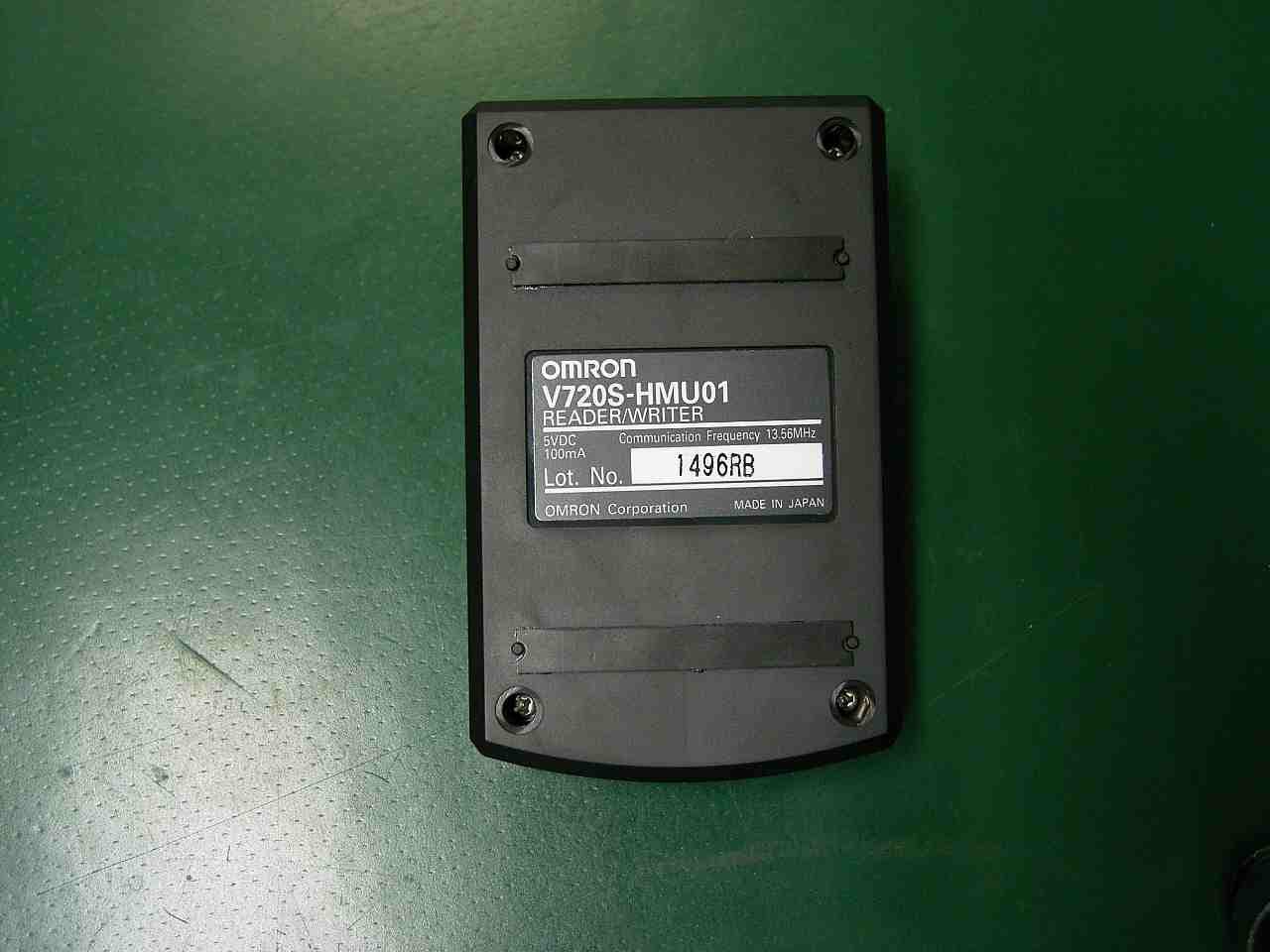
OZGV720SHMU01
Jan 07, 2008RFID Transmitter
Equipment Class
DXX - Part 15 Low Power Communication Device Transmitter
OZGV680-CHXD
Nov 08, 2007RFID Reader/Writer
Equipment Class
DXX - Part 15 Low Power Communication Device Transmitter
OZGV720SBC5D4A-US
Oct 09, 2006RF ID Reader
Equipment Class
DXX - Part 15 Low Power Communication Device Transmitter
OZGV740-BA50C2A
Jan 12, 2006RFID Reader Transmitter
Equipment Class
DSS - Part 15 Spread Spectrum Transmitter
OZGV740-BA50CX4
Sep 01, 2005Radio Identification System
Equipment Class
DSS - Part 15 Spread Spectrum Transmitter