OZULF01142UControl Transmitter
NASCO Fort Atkinson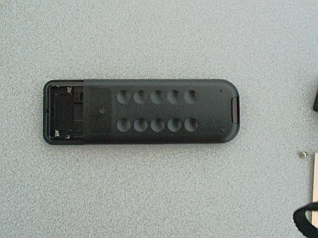
Click to zoom
Application Details
- Equipment Class
- DSC - Part 15 Security/Remote Control Transmitter
- Date of Grant
- Mar 12, 2001
- Application Purpose
- Original Equipment
- Date of Application
- May 11, 2000
- Equipment Note
- Control Transmitter
- Frequency Range
- 417.96000000 - 418.08000000
- Company
- NASCO Fort Atkinson
- Country
- United States
Documents & Files
Document Text
Text extracted from the exhibit documents filed with the FCC. Open a document above to read the original.
Users Manual
Users’ Manual for Nasco Auscultation Remote Control Summary: The remote control is the main user interface, where the mode of operation is selected and the display gives the user feedback about current operation. Operation: • To begin using the Auscultation system, press the red Power button. This turns on the remote control and sends a signal to the stethoscope to activate it, as well. After the unit is activated, the display will be in the “status” mode, displaying the current menu settings for the heart and lung conditions. • To select a new condition, press either the Heart or Lung button. This will put the display into the menu mode. The user can select a condition by either using the number buttons, or by viewing the conditions in sequence using the Scroll button. • When the desired conditions for heart and lung are selected, press the Enter button to transmit the new set of conditions to the stethoscope. When the Enter button is pressed, the display will return to status mode. A transmission icon shows that the signal is being sent to the stethoscope. • To turn off the unit, press the Power button. Unit uses two AAA alkaline batteries WARNING: NO USER SERVICEABLE PARTS INSIDE CASE
Attestation Statements
May 26, 2000 Andy Leimer Processing Engineer [email protected] Reference: Confirmation number: EA97572 FCC I.D. number: OZULF01142U Mr. Leimer: Please consider this our letter of request for confidentiality for all the schematics, and the block diagrams on this filing. We have applied for patents and feel we need the confidentiality to protect our interests with this product. Dan Christianson Director Health Care Nasco [email protected]
ID Label/Location Info
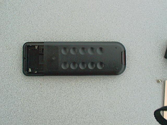
View is of REMOTE CASE BACK Label area dimensions: 1.550” x 0.770” (Corner radius = 0.100”) Battery Compartment FCC ID: OZULF01142U Nasco Auscultation Remote Control Model LF01142U This device complies with part 15 of the FCC Rules. Operation is subject to the following two conditions: (1) This device may not cause harmful interference, and (2) this device must accept any interference received, inclu- ding interference that may cause undesired operation.
Operational Description
Operational description for Nasco Auscultation Remote Control Operational description: When the remote is powered on, it transmits a signal to activate the main circuit board. The user selects a heart condition and a lung condition using the remote keypad. When the desired conditions are selected, the user presses the “enter” button, which begins transmission of the signal to the receiver board in the stethoscope. The information transmitted is used by the main board to generate the appropriate heart and lung sounds based on the conditions selected, and which transponder is activating the stethoscope. Any time the unit transmits, the duration of transmission is less than 5 seconds.
Parts List/Tune Up Info
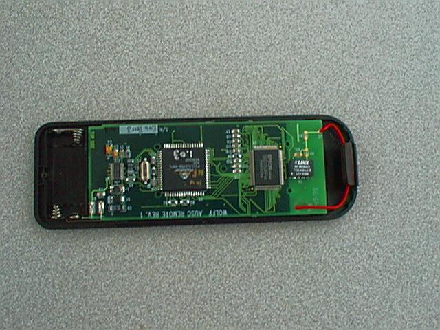
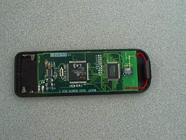
Nasco Auscultation Remote Control Model LF01142U PARTS LIST: QtyLocation Mfrg #DescriptionMfrPkg 1C2TAJA105 Cap, tant, 1uF, 20VKemet1206E/3216M ‘A’ [H=1.6/.063] 1C4TAJB106 Cap, tant, 10uF, 10VPanasonic1411E/3528M ‘B’ [H=1.9/.075] 2C3,6TPSC476Cap, Tant, 47uF, 10V, LAVX6032 ('C' case) 10C1,5,7,8,9C1206C10Cap, Cer, .1uFKemet1206 1U1MAX769E EI IC, Controller, SMPSMAXIMSOIC-28 1L1DS1608C- Inductor, 68uHCOILCRAF1608 1R1RM73B2B T153J Resis, 5% 15KKOA1206 1R5RM73B2BTResis, 5% 47KKOA1206 1R8RM73B2BTResis, 5% 1KKOA1206 1D110BQ015 Diode, SchottkeI.R. 1X1see doc Crystal, 4MHzsee doc file 1U2PIC17LC7 56-08/L IC, MicrocontrollerMICROCH PLCC-68 1U3SED1526 FOA IC, Controller, DisplayEPSON50 2C14,C15ECU- V1H270JC M Cap, 27pFPanasonic1206 2R2,R3RK73H2B T4123F Resis, 412K, 1%KOA1206 1R6RM73B2BTResis, 1MKOA1206 N/AR4,7 1U4TXM-418- LC Module, Transmitter, RFLINX 1AN1Antenna Wire, insulated, solid, 20gg 1N/APCB, Remote N/AB1-ABatt. Spring plus N/AB1-BBatt. Spring minus 1Memo Express LCD LCDWIRELESS TECH TUNE UP INFORMATION: Tune up procedure: NONE - transmitter is a sealed module (Linx TMX-418-LC) Performance Data for Linx TMX-418-LC: Output Power: Min: -4dBm; typical: -1dBm; Max: +4dBm (output connected to 50 Ohm load) Frequency of carrier: Min: 417.96 MHz; Typical: 418.02 MHz; Max: 418.08 MHz Harmonic Emissions: -40 dBc (output connected to 50 Ohm load)
Test Report
Page 1 of 10 TEST RESULTS REPORT FOR DVC INDUSTRIES, INC. 4080 BENNETT ROAD, SUITE A TOLEDO, OHIO 43612 U.S.A. Devices Tested: ASCULTATION Trainer, S/N: Prototype Consisting of 418 MHz remote control, stethoscope and mannequin with internal responding sensors Report 1160 Report date: April 3, 2000 Test date: March 22, 2000 Summary Report The following tests were performed on these devices • Electrostatic Discharge in accordance with EN 61000-4-2 • Immunity to radiated electromagnetic fields in accordance with EN 61000-4-3 • Immunity to radiated pulse modulated electromagnetic fields in accordance with ENV50204. • Radiated Emission in accordance with EN55011, Class B • Spectral characteristics of the remote transmitter with regard to the requirements of E^TSI 400 683 and the FCC Part 15 for intentional radiators. The devices satisfy the requirements of the above EU standards as well as the remote passing the FCC part 15 requirements for an intermittently use d inte ntional radiator. This report contains 10 pages and shall not be reproduced except in full without written permission of Compliance Labs, Inc. _________________________________________ Sheldon Gruber, Vice-President Page 2 of 10 1. INTRODUCTION Compliance Labs, Inc. Compliance Labs, Inc. (CLI) has facilities which conform to the requirements of EN 45001: 1989, General criteria for the operation of testing laboratories. This laboratory is certified by the United Kingdom Company TRL EMC, LTD, and a competent body, to comply with the EMC/EMI testing procedures established by the European Union. CLI’s facilities include a three-meter semi-anechoic chamber, an open area test site (OATS) with both a three and ten- meter capability. The OATS normalized site attenuation satisfies CISPR 16 and ANSI C63.4- 1992 requirements and is listed with Industry Canada for emissions testing as File IC 3007 as well as the FCC. The equipment is in compliance with IEC 1000-4-4 for fast transient immunity testing, IEC 1000-4-2 for electrostatic discharge testing and IEC 1000-4-3 for radiated, radio- frequency, electromagnetic immunity testing to 10 V/m E-fields and surge immunity according to IEC 1000-4-5. The receiver used for emission testing is in conformance with CISPR 16. Calibration for all equipment is current. Supporting data will be provided upon request. 2. SPECIFIC TEST RESULTS 2.0 Device Description These devices serve as a trainer for medical technicians and are battery operated. The remote transmitter, operating at 418 MHz, serves as a control for the responsive sensors within the mannequin. The instructor can set the characteristic waveforms which the students then are requested to interpret by listening with their stethoscopes. 2.1 Immunity Tests The following tests were performed in the Compliance Labs facility where the temperature typically ranges from 19 to 30 degrees Celsius and a relative humidity from 20 to 60 percent. These measurements are made using an electronic hygrometer. The tests described herein were performed at 22° C and RH between 29 and 30%. 2.1.1 Electrostatic Discharge Immunity These EUT's were tested to ±4 kV contact and ±8 kV non-contact as required by EN 61000-4-2. The device enclosure is non-conductive. Neither of the EUT's were effected during or after the discharges were applied- a category A response. The temperature was 23° C and RH 40%. 2.1.2 Immunity to Radiated Radio Frequency Fields. Both EUT's. (remote controller, stethoscope and mannequin) were placed on a non-conducting table 0.8-m from the ground plane in the uniform field region, 3-meters from the EMCO 3143 antenna. The test used a sweep from 80 MHz to 1000 MHz at the level of 3 volts/meter, modulated at 1 kHz, as measured by a Chase Model EMC 20 electric field meter. The frequency was increased in steps of 1 Percent of the previous frequency in accordance with the generic immunity standard, EN50082-2: 1998. Dwell time at any one frequency was approximately 1/2 second, deemed long enough for the EUT's to respond. Four orientations of the EUT's w ere tested with frequency sweeps in both horizontal and vertical polarization. The EUT's passed this test with performance criterion A as required. The devices were tested at 897 MHz for immunity to radiated pulse modulated electromagnetic fields in accordance with ENV50204 and passed without a problem. Page 3 of 10 EN60101-2 suggests testing beyond the level required for EN50082-1. The tests performed at 10 V/m went from 800 MHz to 1 GHz. The EUT's continued to function normally. Fig.1 EUT in anecxhoic chamber for radiated RF immunity testing. The remote control is visible on the table next to the receiver. 3.1 Emission Tests Fig.2 EUT on 10-m OATS for radiated RF emission testing. The devices were tested for emission on the 10-m OATS. The following figures give an indication of the level of emitted noise. All sweeps are performed using peak detection. Page 4 of 10 Fig.3. EUT emission on 10-m OATS taken with the broadband antenna vertically polarized and 1.0-m above groundplane. The s we e p us e s p e a k d e te c tio n. Blue is with the EUT o n. The IS M c la s s B q ua i- p e a k limit is s ho wn. Fig.4. EUT emission on 10-m OATS taken with the broadband antenna vertically polarized and 1.5-m above groundplane. The s we e p us e s p e a k d e te c tio n. Blue is with the EUT o n. The IS M c la s s B q ua i- p e a k limit is s ho wn. Page 5 of 10 Fig.5. EUT emission on 10-m OATS taken with the broadband antenna vertically polarized and 2-m above groundplane. The s we e p us e s p e a k d e te c tio n. Blue is with the EUT o n. The IS M c la s s B q ua i- p e a k limit is s ho wn. Fig. 6. The emission from the EUT’s with a horizontally polarized broadband antenna 10-m from it. The antenna is 1.0-m up. Re d is the a mb ie nt. The c la s s B limit line is s ho wn. Page 6 of 10 Fig. 7. The emission from the EUT’s with a horizontally polarized broadband antenna 10-m from it. The antenna is 2.0-m up. Re d is t…
Text truncated - open the document above for the full version.
Contact Information
Applicant
Timothy J Walter(Research and Development Manager)
Test Firm
F-Squared LaboratoriesJohn Harrington
Technical Specifications
| # | Rule Parts | Frequency Range | Power Output |
|---|---|---|---|
| 1 | 15C | 417.96 MHz - 418.08 MHz | - |
Other Applications from NASCO Fort Atkinson
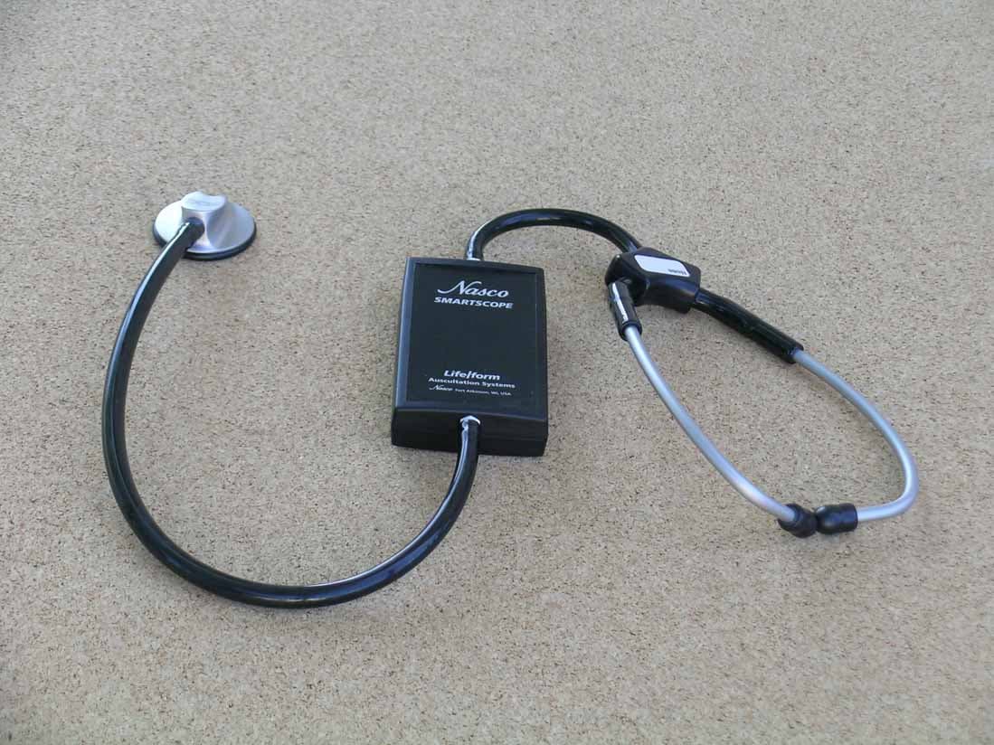
OZULF01144U
Oct 14, 2006SmartScope
Equipment Class
DCD - Part 15 Low Power Transmitter Below 1705 kHz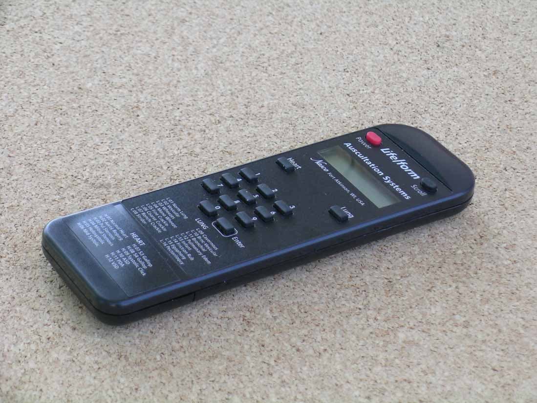
OZURF01148U
Oct 14, 2006SmartScope Remote Control
Equipment Class
DSC - Part 15 Security/Remote Control Transmitter