OZURF01148USmartScope Remote Control
NASCO Fort Atkinson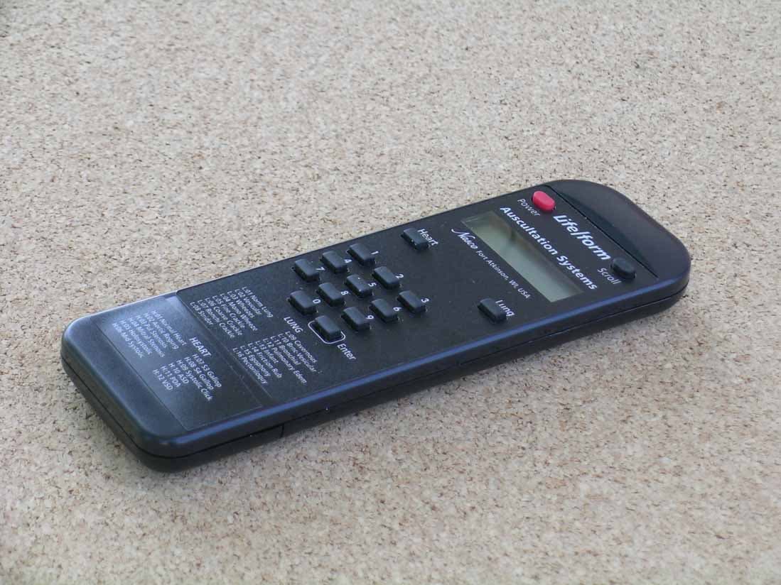
Click to zoom
Application Details
- Equipment Class
- DSC - Part 15 Security/Remote Control Transmitter
- Date of Grant
- Oct 14, 2006
- Application Purpose
- Original Equipment
- Date of Application
- Oct 14, 2006
- Equipment Note
- SmartScope Remote Control
- Frequency Range
- 433.92000000 - 433.92000000
- Company
- NASCO Fort Atkinson
- Country
- United States
Documents & Files
Document Text
Text extracted from the exhibit documents filed with the FCC. Open a document above to read the original.
Users Manual
User's Manual requirement Joseph Brunett <[email protected]> Desmarais, Nicolas: DEB Lab <[email protected]> Tue, Sep 19, 2006 at 10:51 AM To: [email protected] Cc: "Valdis V. Liepa" <[email protected]> Dear Mr. Brunett, It is permissible to have a device sold without a user's manual, as long as the labeling information (RSS-GEN section 5.2) and the applicable statements (RSS-GEN section 7.1.5) are on the device. In this case, you do not need to provide a user's manual with your application. Best regards, Nicolas DesMarais Certification Officer Industry Canada Certification & Engineering Bureau Spectrum Engineering 3701 Carling Avenue, Bldg.94, P.O. Box 11490, Station H Ottawa, Ontario K2H 8S2 (613) 990-5329 Fax: (613) 990-4752 E-mail: [email protected] Web: http://strategis.ic.gc.ca /certification [Quoted text hidden] Page 1 of 1Gmail - User's Manual requirement 10/5/2006http://mail.google.com/mail/?ik=4cddaab9f2&view=pt&th=10dc742fcd3576a6&search=q... Response to Inquiry to FCC (Tracking Number 474491) Joseph Brunett <[email protected]> Generic Office of Engineering Technology <[email protected]> Wed, Sep 27, 2006 at 12:30 PM To: [email protected] Inquiry: Please address the following two questions. 1) Is it permissible for a Part 15 device to be sold without a users manual (or other paper/electronic document) so long as all required statements (id number, rf hazard and interference warnings, etc...) are placed directly on the device? 2) If all required statements are placed on a device, must a users manual (or other paper/electronic document) be provided when applying for certification? Thanks. JDB --- Reply from Customer on 09/22/2006 --- Just to verify I am understanding this correctly. Most applications require a users manual exhibit. However, that exhibit may be comprized of an ID label drawing or photograph, so long as that label clearly demonstrates all information required of the users manual for compliance. Please confirm. JDB Response: Your understanding is correct. Since the manufacturer does not supply an actual user manual, ! then they may use the product label which contains the required FCC information as a user manual exhibit. Do not reply to this message. Please select the Reply to an Inquiry Response link from the OET Inquiry System to add any additional information pertaining to this inquiry. Page 1 of 1Gmail - Response to Inquiry to FCC (Tracking Number 474491) 10/5/2006http://mail.google.com/mail/?ik=4cddaab9f2&view=pt&th=10df01cef203e919&search=ca...
Attestation Statements
Re: Certification for Nasco Transmitter Model(s): RF01148U FCC ID: OZURF01148U IC: 6758A-RF01148U POWER OF ATTORNEY A letter granting Valdis V. Liepa the Power of Attorney is on file and can be provided when so requested. Re: Certification for Nasco Transmitter Model(s): RF01148U FCC ID: OZURF01148U IC: 6758A-RF01148U REQUEST FOR CONFIDENTIALITY Pursuant to 47 CRF 0.459, Nasco requests that a part of the subject application be held confidential. This comprises Exhibits (5) Schematics (10) Parts List (Part of Exhibit only) Nasco has spent substantial effort in developing this product and it is one of the first of its kind in industry. Having the subject information easily available to "competition" would negate the advantage they have achieved by developing this product. Not protecting the details of the design will result in financial hardship. If there are any questions regarding this request, please contact me at the above address or call 734-483-4211, fax 734-647-2106 or e-mail [email protected]. Sincerely, Valdis V. Liepa Research Scientist University of Michigan October 12, 2006 Re: Certification for Nasco Transmitter Model(s): RF01148U FCC ID: OZURF01148U IC: 6758A-RF01148U STATEMENT OF MODIFICATIONS During pre-testing, the fundamental emission was determined to be greater than the allowable limit. Working with the manufacturer the test lab changed the resistor values in R9 and R10 to 100 Ohms and 47 Ohms, respectively. These changes brought the DUT emissions into compliance with FCC and IC regulations. These changes are reflected in the provided Bill of Materials and Schematics. (Also see Section 3.1 of the attached Test Report). _____________________ Valdis V. Liepa Research Scientist Re: Certification for Nasco Transmitter Model(s): RF01148U FCC ID: OZURF01148U IC: 6758A-RF01148U GENERAL PRODUCT INFORMATION The device, for which certification is pursued, has been designed by: Nasco 901 Janesville Ave. Fort Atkinson, WI 53538 Mr. Neil P. Caffrey [email protected] Tel: (920) 563-2446 625 Fax: (920) 563-5784 It will be manufactured by: Nasco 901 Janesville Ave. Fort Atkinson, WI 53538 Mr. Neil P. Caffrey [email protected] Tel: (920) 563-2446 625 Fax: (920) 563-5784 Canadian Contact: Spectrum Educational Supplies Limited 150 Pony Drive Newmarket, Ontario L3Y 7B6 Brian Arthurs Tel: (905) 898-0031, ext. 4901 Fax: (905) 898-0035
Block Diagram
U4 TX-433-LC 433 MHz Processor U2 PIC17C756 Power supply with batteries Keypad U3 SED1526 Display Driver LCD Pinnacle Technology Group X-TAL X1 4.0 MHz ANTENNA OUT
Cover Letter(s)
October 9, 2006 American Telecommunications Certification Body, Inc. 6731 Whittier Avenue Suite C110 McLean, VA 22101 RE: Certification Application FCC ID: OZURF01148U IC: 6758A-RF01148U Model(s): RF01148U Please find enclosed application materials for certification of Nasco RF01148U Transmitter. Note: 1) portions of this submittal are filed Confidential 2) a list of the modifications made is provided in Attestations. If there are any questions regarding the application or testing performed, please contact me at the above address or call 734-483-4211, fax 734-647-2106, or e-mail [email protected]. Sincerely, Valdis V. Liepa Research Scientist
Test Report
University of Michigan Radiation Laboratory FCC Part 15, IC RSS-210/Gen - Test Report No. 415031-322 Page 1 of 11 The University of Michigan Radiation Laboratory 3228 EECS Building Ann Arbor, MI 48109-2122 Tel: (734) 764-0500 Measured Radio Frequency Emissions From Nasco Transmitter Model(s): RF01148U Report No. 415031-322 October 12, 2006 Copyright © 2006 For: Nasco 901 Janesville Ave. Fort Atkinson, WI 53538 Contact: Gerry Sivulka [email protected] Tel: (419) 478-6600 ext 104 PO: Verbal Tests supervised by: Measurements made by: Valdis V. Liepa Report approved by: _____________________ Joseph D. Brunett Valdis V. Liepa Test Report Prepared by: Joseph D. Brunett Research Scientist Summary Tests for compliance with FCC Regulations Part 15, Subpart C, and Industry Canada RSS-210/GEN, were performed on Nasco model(s) RF01148U. This device is subject to the Rules and Regulations as a Transmitter. In testing completed on August 23, 2006, the device tested in the worst case met the allowed FCC specifications for radiated emissions by 1.4 dB (see p. 6). Besides harmonics, there were no other significant spurious emissions found; emissions from digital circuitry were negligible. The conducted emission tests do not apply, since the device is powered from a two 1.5 VDC batteries. University of Michigan Radiation Laboratory FCC Part 15, IC RSS-210/Gen - Test Report No. 415031-322 Page 2 of 11 1. Introduction Nasco model RF01148U was tested for compliance with FCC Regulations, Part 15, adopted under Docket 87-389, April 18, 1989 as subsequently amended, and with Industry Canada RSS-210/Gen, Issue 6, September 2005. The tests were performed at the University of Michigan Radiation Laboratory Willow Run Test Range following the procedures described in ANSI C63.4-2003 "Methods of Measurement of Radio-Noise Emissions from Low-Voltage Electrical and Electronic Equipment in the Range of 9 kHz to 40 GHz". The Site description and attenuation characteristics of the Open Area Tes Site are on file with FCC Laboratory, Columbia, Maryland (FCC Reg. No: 91050) and with Industry Canada, Ottawa, ON (File Ref. No: IC 2057). 2. Test Procedure and Equipment Used The pertinent test equipment commonly used in our facility for measurements is listed in Table 2.1 below. The middle column identifies the specific equipment used in these tests. Table 2.1 Test Equipment. Test Instrument Eqpt. Used Manufacturer/Model Spectrum Analyzer (0.1-1500 MHz) Hewlett-Packard, 182T/8558B Spectrum Analyzer (9kHz-22GHz) X Hewlett-Packard 8593A SN: 3107A01358 Spectrum Analyzer (9kHz-26GHz) X Hewlett-Packard 8593E, SN: 3412A01131 Spectrum Analyzer (9kHz-26GHz) Hewlett-Packard 8563E, SN: 3310A01174 Spectrum Analyzer (9kHz-40GHz) Hewlett-Packard 8564E, SN: 3745A01031 Power Meter Hewlett-Packard, 432A Power Meter Anritsu, ML4803A/MP Harmonic Mixer (26-40 GHz) Hewlett-Packard 11970A, SN: 3003A08327 Harmonic Mixer (40-60 GHz) Hewlett-Packard 11970U, SN: 2332A00500 Harmonic Mixer (75-110 GHz) Hewlett-Packard 11970W, SN: 2521A00179 Harmonic Mixer (140-220 GHz) Pacific Millimeter Prod., GMA, SN: 26 S-Band Std. Gain Horn S/A, Model SGH-2.6 C-Band Std. Gain Horn University of Michigan, NRL design XN-Band Std. Gain Horn University of Michigan, NRL design X-Band Std. Gain Horn S/A, Model 12-8.2 X-band horn (8.2- 12.4 GHz) Narda 640 X-band horn (8.2- 12.4 GHz) Scientific Atlanta , 12-8.2, SN: 730 K-band horn (18-26.5 GHz) FXR, Inc., K638KF Ka-band horn (26.5-40 GHz) FXR, Inc., U638A U-band horn (40-60 GHz) Custom Microwave, HO19 W-band horn(75-110 GHz) Custom Microwave, HO10 G-band horn (140-220 GHz) Custom Microwave, HO5R Bicone Antenna (30-250 MHz) X University of Michigan, RLBC-1 Bicone Antenna (200-1000 MHz) X University of Michigan, RLBC-2 Dipole Antenna Set (30-1000 MHz) X University of Michigan, RLDP-1,-2,-3 Dipole Antenna Set (30-1000 MHz) EMCO 2131C, SN: 992 Active Rod Antenna (30 Hz-50 MHz) EMCO 3301B, SN: 3223 Active Loop Antenna (30 Hz-50 MHz) EMCO 6502, SN:2855 Ridge-horn Antenna (300-5000 MHz) X University of Michigan Amplifier (5-1000 MHz) X Avantak, A11-1, A25-1S Amplifier (5-4500 MHz) X Avantak Amplifier (4.5-13 GHz) Avantek, AFT-12665 Amplifier (6-16 GHz) Trek Amplifier (16-26 GHz) Avantek LISN Box University of Michigan Signal Generator Hewlett-Packard 8657B University of Michigan Radiation Laboratory FCC Part 15, IC RSS-210/Gen - Test Report No. 415031-322 Page 3 of 11 3. Device Under Test 3.1 Identification The DUT is a 433.92 MHz transmitter, approximately 2.5 x 7.5 x 0.5 inches in size. The carrier is LC stabilized with highly optimized SAW internal to the RFIC package. Data and display driving are provided by a microprocessor timed via a 4.0 MHz crystal. The antenna is a trace on the PCB. The DUT was designed and manufactured by Nasco, 901 Janesville Ave., Fort Atkinson, WI 53538. It is identified as: Nasco Transmitter Model: RF01148U FCC ID: OZURF01148U IC: 6758A-RF01148U 3.2 Models There is only a single model of the device, and that model was modified for CW transmission once modulation related data was taken. 3.3 Modes of Operation The DUT is manually activated and ceases to transmit within 5 seconds of deactivation. See Figure 6.1. 3.4 EMI/EMC Relevant Modifications During pre-testing, the fundamental emission was determined to be greater than the allowable limit. Working with the manufacturer the test lab changed the resistor values in R9 and R10 to 100 Ohms and 47 Ohms, respectively. These changes brought the DUT emissions into compliance with FCC and IC regulations. These changes are reflected in the provided Bill of Materials and Schematics. 4. Emission Limits The DUT tested falls under the category of an Intentional Radiators and the Digital Devices. For FCC, it is subject to Part 15, Subpart C, (Section 15.231(a-c), 15.209), and Subpart A, (Section 15.33). For Industry Canada it is subject to RSS-210 (Section 2.6 and 2.7). The applicable testing frequencies with corresponding emission limits are given in Tables …
Text truncated - open the document above for the full version.
Contact Information
Applicant
Timothy J Walter(Research and Development Manager)
Technical Contact
University of MichiganValdis V Liepa
[email protected]734 483 4211
1301 Beal Ave · Ann Arobor, Michigan · United States
Test Firm
University of MichiganValdis Liepa
Technical Specifications
| # | Rule Parts | Frequency Range | Power Output |
|---|---|---|---|
| 1 | 15.231 | 433.92 MHz - 433.92 MHz | - |
Other Applications from NASCO Fort Atkinson
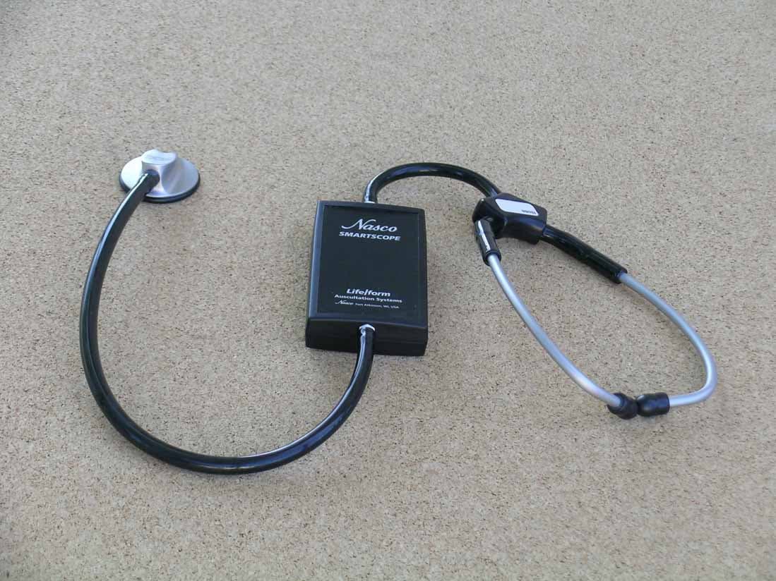
OZULF01144U
Oct 14, 2006SmartScope
Equipment Class
DCD - Part 15 Low Power Transmitter Below 1705 kHz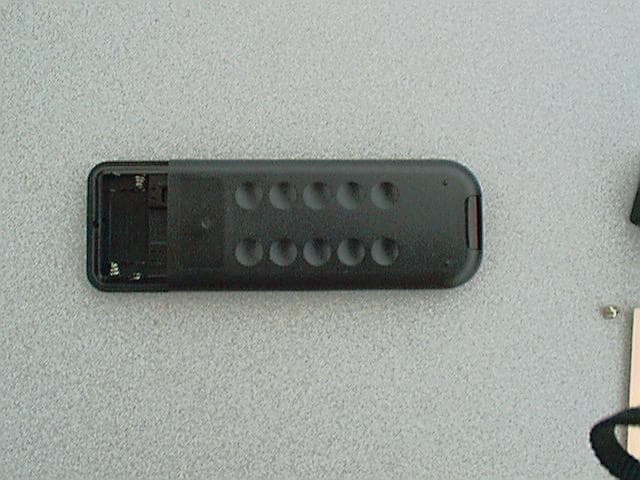
OZULF01142U
Mar 12, 2001Control Transmitter
Equipment Class
DSC - Part 15 Security/Remote Control Transmitter