P39-YP3700PDA
G.Mate, Inc.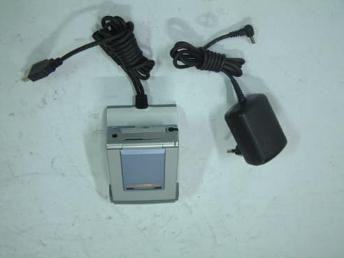
Click to zoom
Application Details
- Equipment Class
- JBP - Part 15 Class B Computing Device Peripheral
- Date of Grant
- Jul 29, 2003
- Application Purpose
- Original Equipment
- Date of Application
- Jul 29, 2003
- Equipment Note
- PDA
- Company
- G.Mate, Inc.
- Country
- South Korea
Documents & Files
Document Text
Text extracted from the exhibit documents filed with the FCC. Open a document above to read the original.
Users Manual
YP3700 User Guide 1 Chapter 1. Overview of YOPY The multimedia PDA YOPY uses the Linux OS developed by G.Mate, Linupy™. With its slim size and folder type design, mobility, and high performance, YOPY is capable of providing entertainment contents such as images, games or music, and the newest information on the Internet from anywhere at any time. 2 What is in the YOPY box? Thank you very much for your purchase of the YOPY. Please check whether you have all of the following items in the YOPY box. - YOPY PDA (Model name is “YP3700) - Cradle - Wireless LAN Card - Ear-microphone - User Manual - CD - Fashion Stylus Pen - AC Adapter 3 YOPY Outside Components Charge LED Charging starts when you put the YOPY on the cradle Red – On charging Green – Fully Charged Scroll Button Recording Upper – For starting record Lower – For stopping record Playing MP3 Upper – For volume up Lower – For volume down Moving the scroll bar on the screen up and down IrDA Communication Port Slot for MMC or SD Card Headphone Jack For listening to music with the Headphone Event LED The colorful blinking light works when you - Open or close the YOPY. - Are reminded with alarm. Stylus Pen Serial/USB Client Port For communicating with PC or charging the battery by connecting the YOPY to the cradle. CompactFlash Slot For wireless LAN card and the other expansion card. [Picture 1-2] YOPY Outside Panels 4 YOPY Inside Components [Picture 1-3] YOPY Inside Panels Reset hole For doing the soft reset with the stylus pen. Execution Button For playing a program o r starting and stopping the MP3 player End Button For stopping the currentl y operating program. Send Button Power Button Speaker Microphone Navigation Keys Key Pad Consisting of the letters, the numbers, the symbols and other function keys. (See Chapter.6 for details) Touch Screen Touching with the Stylus. 65,536 Colors. Front Light. Note. For the detailed explanation to the way to use the keyboard conveniently and easily, see the guide for the Keyboard use in the Chapter 6. 5 Chapter 2. Initial settings of YOPY Have you checked all of the components of the YOPY? This chapter explains the basic settings you must follow, before using your YOPY for the first time, step by step. 6 You should set the YOPY in the following orders before you use it for the first time. 1. Soft reset You should tap the Soft Reset Hole (See the Figure. 1-3) with the stylus. There appears the “Welcome” screen after the booting screen with the Linux logo (Penguin) shows up. 2. ‘Welcome’ Screen The YOPY has woken up now! Please tap the screen with the stylus gently. [Welcome Screen] 3. Calibrate Coordinate adjustment lets your YOPY exactly sense the elements on your screen, when tapping them with the Stylus. Tap the center of the cross mark ( ) on your screen with the Stylus until the screen changes. (The new screen shows up after you correctly tap the cross mark in each five different places). [Calibraton Screen] 7 4. Setting the time The below time setting screen follows calibrating. You can set the city and the current time and date. You can automatically have the time and the date of the city around the world when you choose it. Icon for setting date Icon for setting time [Setting Time and Date] Note Please refer to the “Setting the time” in the Chapter 10 for more information. 8 Chapter 3. MyPIMS With the MyPIMS program you can edit, add and delete the data in the PIMS programs of the YOPY such as Schedule, Task, and Contact. In addition, MyPIMS has the function of file transfer between the YOPY and your PC and one of the PIMS data backup and recovery. The features of your PC required to install and use the MyPIMS program are as follows: ■ Windows 98SE, Windows 2000, Windows XP, Windows ME, Red Hat 7.1 ■ Pentium II processor or greater ■ 64MB RAM or more ■ Available hard disk space more than 150 MB ■ CD-ROM drive ■ VGA Monitor or better ■ Mouse ■ One USB port 9 Installing MyPIMS How to install the MyPIMS Program on your PC? 1. Hardware Wizard automatically runs when you put the CD included in the YOPY package into the CD-ROM. Click on “MyPIMS Installation” 2. Your PC is warming up for installing the MyPIMS program. 3. Installing starts with the below screen. Click on the “Next” button. 4. The program is automatically installed in the directory of the C drive unless you set a directory on the below screen yourself. Click on the “Next” button. 10 5. The installation of the program is on the process. 6. Installation has been complete. Click on the “Finish” button. And then, you have MyPIMS Icon ( ) on the background. 11 Connecting the cradle to your desktop PC Now you can connect the cradle to your desktop PC if you have finished installing the MyPIMS program on your desktop PC. How to connect the cradle to your PC? There are the two cables in the cradle. One is for connecting to the power outlet and the other is for connecting to the USB port of the PC. Please connect the AC adaptor of the cradle to the power outlet and the USB cable of the cradle to the USB port of the PC. Note. After connecting the cradle to the PC, you must install the Device Driver on your PC for the new hardware device (USB device). For more information on installing the device driver, see the “Installing the Device Driver” part in the following section.. 12 Installing the Device Driver You should install the Device Driver on your PC to make it recognize the YOPY. You can, therefore, use the MyPIMS program. Please install the driver in the following order. 1. Put the YOPY on the cradle after connecting the USB cable of the cradle to the USB port of the PC. 2. The “Found New Hardware Wizard” screen appears when the YOPY is put on the cradle. Click on the “Next” button after inserting the CD from the YOPY package in the CD-ROM of your PC. 3. You should mark on the box of “Search removable media” and then, click on the “Next” button. 4. The installation of the Device Driver is on the process. 13 5. The hardware wizard has finished…
Text truncated - open the document above for the full version.
Block Diagram
YOPY 3700 BLOCK DIAGRAM `` SA1 1 10 (U1) Serial4(MCP) 12M Hz Flash 32M B (U2 , U3 ) SDRAM 128M B ( U 6, 7, 31, 32) UDA1341 (U8 ) PC SPK (0.5W ) 1.8V(U37) LEDs HeadP h o n e Serial2 (ICP) Serial0 ( USB ) YOPY 3700 MI C UC B 1200 (U16) T ouch Screen MMC I/F 22 P C onn (C 22) IrDA (U46) LCD Char ger 1 U50 BA T 1 M Q 1 132 (U23) POWER FET s (U 2 5, U 2 6, U 2 7 SPI DC Adaptor 5V 2A Serial3(UAR T) Serial4(SSP) GP USB/ RS- 232C MMC T y p e Mem o r y ,etc CDMA,GPS,etc Serial1 ( UAR T ) PL L 1700( U14) , L V393( U11) L3 I/F Side,FNKeys UCB_GPIOs 20 P Jacket C onn (EC1) Key Board 3. 6864M Hz( X 1) 32. 768KHz( X 2) 27M Hz(Y1) 48M Hz(Y2) SDCLK 103M Hz 1 . I2 S I/F TS I/F ADC L i ne Buffe r s ( U61 , U62 , U63 ) W_ LED Driver ( U 51) Char ger DC5V MQ L V 164 ( U501 ) SPKAMP (U9 ) BATT,5V,VBUS CF I/F CF T y p e WL AN ,M em . BA T 2 Char ger 2 U52 +-15V(U56) 5V(U53) 3.3V(U33) 8LED RS- 232C
External Photos
Test report Our reference : KEL03-F06069 Page : B1 of Appendix Issued date : 2003-07-08 Korea EMC Laboratory Appendix-B : External Photographs of E.U.T <FRONT VIEW OF EUT> <REAR VIEW OF EUT>
ID Label/Location Info
Test report Our reference : KEL03-F06069 Page : D1 of Appendix Issued date : 2003-07-08 Korea EMC Laboratory Appendix-D : FCC ID label location information and Sample - FCC ID label location information The label included following statement will be attached on the bottom side of product. - FCC ID label sample
Internal Photos
Test report Our reference : KEL03-F06069 Page : C1 of Appendix Issued date : 2003-07-08 Korea EMC Laboratory Appendix-C : Internal Photographs of E.U.T <INTERNAL VIEW OF E.U.T> Test report Our reference : KEL03-F06069 Page : C2 of Appendix Issued date : 2003-07-08 Korea EMC Laboratory <FRONT VIEW OF MAIN BOARD> Test report Our reference : KEL03-F06069 Page : C3 of Appendix Issued date : 2003-07-08 Korea EMC Laboratory <REAR VIEW OF MAIN BOARD> Test report Our reference : KEL03-F06069 Page : C4 of Appendix Issued date : 2003-07-08 Korea EMC Laboratory <FRONT VIEW OF CRADLE> Test report Our reference : KEL03-F06069 Page : C5 of Appendix Issued date : 2003-07-08 Korea EMC Laboratory <REAR VIEW OF CRADLE > Test report Our reference : KEL03-F06069 Page : C6 of Appendix Issued date : 2003-07-08 Korea EMC Laboratory <FRONT VIEW OF CRADLE BOARD> Test report Our reference : KEL03-F06069 Page : C7 of Appendix Issued date : 2003-07-08 Korea EMC Laboratory <REAR VIEW OF CRADLE BOARD> Test report Our reference : KEL03-F06069 Page : C8 of Appendix Issued date : 2003-07-08 Korea EMC Laboratory <FRONT VIEW OF KEY BOARD> Test report Our reference : KEL03-F06069 Page : C9 of Appendix Issued date : 2003-07-08 Korea EMC Laboratory <REAR VIEW OF KEY BOARD> Test report Our reference : KEL03-F06069 Page : C10 of Appendix Issued date : 2003-07-08 Korea EMC Laboratory <FRONT VIEW OF LCD BOARD> Test report Our reference : KEL03-F06069 Page : C11 of Appendix Issued date : 2003-07-08 Korea EMC Laboratory <REAR VIEW OF LCD BOARD>
Test Report
CERTIFICATE OF COMPLIANCE 352 Youngduk-Ri, Kihung-Eup, Yongin-City, Kyunggi-Do, Korea 449-908 TEL : (82)31-206-4693 FAX : (82)31-206-3051 http://www.kesilab.com [email protected] http://www.koreaemc.co.kr [email protected] (CLASS B) CERTIFICATION OF COMPLIANCE is hereby issued to the named Applicant and is VALID ONLY for the equipment identified below: Date of Tested : July. 04. 2003 Applicant’s Name : G. Mate, Inc. Applicant’s Address : 3F, Kyungdong Bldg.4-4, Suenae-Dong, Pundang-Ku, Sungnam-Si, Kyunggi-Do, 463-020, Korea Manufacturer’s Name : G. Mate, Inc. Manufacturer’s Address : 3F, Kyungdong Bldg.4-4, Suenae-Dong, Pundang-Ku, Sungnam-Si, Kyunggi-Do, 463-020, Korea Declares that the product Product Description : PDA Brand Name : YOPY Model Number : YP3700 FCC ID : P39-YP3700 Conforms to FCC Rules and Regulations Part 15 Subpart B requirements. This product herewith complies with the requirements of the FCC Rules and Regulations as listed below: Part 15.107: Conducted Emissions. Part 15.109: Radiated Spurious Emissions. TESTED and CERTIFIED by: KOREA EMC LABORATORY 352 Youngduk-Ri, Kihung-Eup, Yongin-Si, Kyunggi-Do, 449-908, KOREA Date : July. 08. 2003 Report No : KEL03-F06069 Authorized Signature : M. S. CHO / President Test report Our reference : KEL03-F06069 Page : 2 of 13 Issued date : 2003-07-08 Korea EMC Laboratory TABLE OF CONTENTS DESCRIPTION Page 0. VERIFICATION OF COMPLIANCE 3 1. GENERAL INFORMATION 1.1 Product Description 4 1.2 Related Submittal(s)/Grant(s) 4 1.3 Tested System Details 4 1.4 System Configuration 4 1.5 General Setup of the test Shield room 5 1.6 Test Facility 5 2. Measurement Procedure 2.1 System test configuration 6 2.1.1 Video mode Justification 6 2.1.2 EUT Exercise S/W 6 2.2 Special Accessories 6 2.3 Equipment Modification 6 2.4 Connected Cable 6 2.5 System Configuration Diagram 6 2.6 Preliminary testing 7 2.7 Shielded Enclosure 7 2.8 Data Reporting Format 7 2.9 Operating Condition 7 2.10 Conditioning of the EUT 7 2.11 Power Line Conducted Emissions 8 2.12 Open field Radiated Emissions Tests 8 3. Measurement Data 3.1 Conducted Emission Data 9 3.2 Conducted Emission Graph 10 3.3 Radiated Emission Data 11 3.4 Summary 12 4. Labeling Requirement 13 Appendix - A : Test set-up Photographs (Conducted and Radiated) - B : External Photographs of E.U.T - C : Internal Photographs of E.U.T - D : FCC ID label location information and sample - E : Block Diagram - F : User’s Manual Test report Our reference : KEL03-F06069 Page : 3 of 13 Issued date : 2003-07-08 Korea EMC Laboratory 0 . VERIFICATION OF COMPLIANCE Equipment Under Test : PDA Model Number : YP3700 Serial Number : Prototype Manufacturer : G. Mate, Inc. 3F, Kyungdong Bldg.4-4, Suenae-Dong, Pundang-Ku,Sungnam-Si, Kyunggi-Do, 463-020, Korea. Type of Test : FCC CLASS B Report Number : KEL03-F06069 Date Tested : July. 04. 2003 Tested By : H.S.CHOI The results show that the sample equipment tested as described in this reports is in compliance with the CLASS B conducted and radiated emission limits of FCC Rules Part 15, Subpart B. Test report Our reference : KEL03-F06069 Page : 4 of 13 Issued date : 2003-07-08 Korea EMC Laboratory 1. GENERAL INFORMATION 1.1 PRODUCT DESCRIPTION The YP3700 is a PDA made by G. Mate, Inc. in Korea. Refer to the user's manual for more information. ITEM SPECIFICATION Power DC 5 V, 2.0 A Processor 206 MHz Strong ARM 32-bit RISC Processor Display 3.5 Inch 240x320 True Color (65K) TFT LCD with Front Light Memory RAM 64MB , 32MB ROM Dimension 7.0 x 10.0 x 2.3 cm 1.2 Related Submittal(s)/Grant(s) N/A 1.3 Tested System Details Type Model Name FCC ID Serial NO Manufacturer PDA YP3700 P39-YP3700 Prototype G. Mate, Inc. Adapter PLA10-5 Verification NONE POWERLINK Corp. Desk Book TGIC-NP2400PA DoC NP2400PA3070012 TRIGEM Adapter ADP-150BB B Verification VBT0321010509 Delta Electronics Inc. USB Mouse U813I-O DoC K020803612 HP Serial Mouse M-CE15 DZLMCE15 LT292R00285 LOGITECH Keyboard SK-2502C DoC M011208657 HP Printer 2225C DSI6XU2225 3119S96116 HP Adapter 0912-TY Verification NONE HANSUNG 1.4 System Configuration Type Model Name Serial NO Manufacturer Remark MAIN B/D CRADLE CRADLE B/D KEY B/D LCD B/D YP3700 REAR YPC-30 YP3500 CRADLE YP3x00 FRONT NL2432DR22-11B NONE NONE NONE NONE NONE G. Mate, Inc. G. Mate, Inc G. Mate, Inc G. Mate, Inc NEC CORP. KOREA KOREA KOREA KOREA KOREA Test report Our reference : KEL03-F06069 Page : 5 of 13 Issued date : 2003-07-08 Korea EMC Laboratory 1.5 General Set-up of the Test Shielded Room The EUT was set up in accordance with the suggested configuration given in FCC measurement Procedure ANSI C63.4 2000. The measurement are performed in the shielded room which dimension is 3.0*7.0*2.5(m). The EUT was placed on a non conductive table which is 1.0*1.5(m), 80 cm above an earthed ground plane and is kept at least 1m from any other earthed ground plane except the rear of table top being removed 40 cm from a vertical conducting plane. Power to the EUT was provided through the LISN(ESH3-Z5, Rohde & Schwarz) which has the Impedance vs Frequency Characteristic in accordance with the conducted setup photographs in Appendix-A Impedance Characteristic of LISN. Peripheral equipment required to provide a functional system(support equipment) for EUT testing was powered through another LISN(KNW-407, KYORITSU). Power to the LISN was filtered to eliminate ambient signal interference. A coaxial type connector which provides a 50 Ohm terminating impedance was provided for the test instrument. The excess length of the power cord was wrapped in the two non metallic pegs attached to the top of the LISN. The two pegs are 9 cm high, approximately 2.0 cm in diameter and that are spaced 6 cm on the center apart. 1.6 Test Facility Location: Korea EMC Laboratory 352 Yungduck-Ri Kihung-Eup,Yongin-City Kyungki-Do,Korea Site : - 3/10m Open Fielded Radiated - Indoor Line Conducted Room(Shielded) The Open Field Radiated and Indoor Line Conducted sites are constructed and calibrated to meet…
Text truncated - open the document above for the full version.
Test Setup Photos
Test report Our reference : KEL03-F06069 Page : A1 of Appendix Issued date : 2003-07-08 Korea EMC Laboratory Appendix-A : Test Setup Photographs - Conducted Setup Photographs LINE CONDUCTED SETUP PHOTOGRAPH - FRONT VIEW LINE CONDUCTED SETUP PHOTOGRAPH - REAR VIEW Test report Our reference : KEL03-F06069 Page : A2 of Appendix Issued date : 2003-07-08 - Radiated Setup Photograph RADIATED EMISSION SETUP PHOTOGRAPH - FRONT VIEW ( 30 - 300 MHz ) RADIATED EMISSION SETUP PHOTOGRAPH - REAR VIEW ( 30 - 300 MHz ) Test report Our reference : KEL03-F06069 Page : A3 of Appendix Issued date : 2003-07-08 Korea EMC Laboratory RADIATED EMISSION SETUP PHOTOGRAPH - FRONT VIEW ( 300- 1000 MHz ) RADIATED EMISSION SETUP PHOTOGRAPH - REAR VIEW ( 300 - 1000 MHz )
Contact Information
Applicant
Kwang_Bok An(Manager)
Test Firm
Korea EMC Laboratory Co., LtdMan-sung Cho
Technical Specifications
| # | Rule Parts | Frequency Range | Power Output |
|---|---|---|---|
| 1 | 15B | - | - |
Other Applications from G.Mate, Inc.
P39-YP3500
Aug 01, 2002PDA
Equipment Class
JBP - Part 15 Class B Computing Device Peripheral
P39-YP3000
Dec 11, 2001Internet Phone
Equipment Class
JBP - Part 15 Class B Computing Device Peripheral