P3CSIM100GPRS Modular
Wacal Inc.
Click to zoom
Application Details
- Equipment Class
- PCB - PCS Licensed Transmitter
- Date of Grant
- Jan 29, 2006
- Application Purpose
- Original Equipment
- Date of Application
- Jan 29, 2006
- Equipment Note
- GPRS Modular
- Frequency Range
- 1850.20000000 - 1908.80000000
- Company
- Wacal Inc.
- Country
- United States
Documents & Files
Document Text
Text extracted from the exhibit documents filed with the FCC. Open a document above to read the original.
Users Manual
1 iTrac with SIM100 GPRS Module Manual I. Introduction.......................................................................................... 2 Features............................................................ ......... ........................2 II. Getting Started...................................................................................... 2 III. Upgrade iTrac with new OS.................................................................4 IV. GPRS Data Setup and Operation...... ......................................................... 5 V. Command Activation Codes and Data Format ................................................ 5 z Functions and options that can be set remotely by text messages(SMS)! ........... 5 z VI. iTrac LED status Indication..................................................................6 VII. iTrac Connections..................... ..................... ..................................8 VIII. iTrac Main Connector Pinout............................................................... 8 IX. Technical Specifications (Main Unit)... .................. ......................................9 2 I. Introduction iTrac is designed with GSM and GPRS tracking unit. All options on the iTrac unit can be updated using GPRS or direct connection with USB data cable, control output by sending an SMS message or use remote controller. Features: SMS, GPRS Support TCP/IP Support 16 GPS channels “all in view” tracking User password management Battery Backup Warning alarm on low battery(default <11.5V) I/O circuit protection Remote control II. Getting Started Warning FCC regulations state that: 1. The Grantee of a license has the responsibility of assuring that all equipment operated under that license confirms to the specifications of the license. 2. The RF power output of a radio transmitter shall be no more than that required for satisfactory technical operation considering the area to be covered and local conditions. 3. The frequency, deviation, and power of a radio transmitter must be maintained within 3 specified limits. It is recommended, therefore, that these three parameters be checked before the station is placed in service. REMEMBER The efficiency of the equipment depends upon a good installation. Telstar recommends that adjustments to this equipment be made ONLY by a certified technician. CAUTION Changes or modifications not expressly approved by the party responsible for compliance could void the user's authority to operate the equipment. The equipment accessories are approved by FCC and only accessories from Telstar Telecom Inc. are qualified for this equipment applications. Detail information see FCC part 15.27. IMPORTANT (a) Only shielded cables, antennas, and special connectors from Telstar Telecom Inc. can be used in this system. Information detailing any alternative method used to supply the special accessories shall be must be approved by FCC and included in the application for a grant of equipment authorization or retained in the verification records, as appropriate. The party responsible for the equipment shall ensure that these special accessories are provided with the equipment. The instruction manual for such devices shall include appropriate instructions on the first page of the text concerned with the installation of the device that these special accessories must be used with the device. It is the responsibility of the user to use the needed special accessories supplied with the equipment. (b) If a device requiring special accessories is installed by or under the supervision of the party marketing the device, it is the responsibility of that party to install the equipment using the special accessories. For equipment requiring professional installation, it is not necessary for the responsible party to market the special accessories with the equipment. However, the need to use the special accessories must be detailed in the instruction manual, and it is the responsibility of the installer to provide and to install the required accessories. (c) Accessory items that can be readily obtained from multiple retail outlets are not considered to be special accessories and are not required to be marketed with the equipment. The manual included with the equipment must specify what additional components or accessories are required to be used in order to ensure compliance with this part, and it is the responsibility of the user to provide and use those components and accessories. (d) The resulting system, including any accessories or components marketed with the equipment, must comply with the regulations. 4 IMPORTANT INFORMATION (FCC Part 15.105) This equipment has been tested and found to comply with the limits for a Class B digital device, pursuant to Part 15 of the FCC Rules. These limits are designed to provide reasonable protection against harmful interference in a residential installation. This equipment generates, uses and can radiate radio frequency energy and, if not installed and used in accordance with the instructions, may cause harmful interference to radio communications. However, there is no guarantee that interference will not occur in a particular installation. If this equipment does cause harmful interference to radio or television reception, which can be determined by turning the equipment off and on, the user is encouraged to try to correct the interference by one or more of the following measures: -- Reorient or relocate the receiving antenna. -- Increase the separation between the equipment and receiver. -- Connect the equipment into an outlet on a circuit different from that to which the receiver is connected. -- Consult the dealer or an experienced radio/TV technician for help. Start Operation: 1. Plug in the USB data cable in both computer and iTrac. Go to device manager and click "COM and LPT" to see which comport the USB data is in (example: got comport 8) 2. Plug in the USB smart driver and see which two com port is generated (exa…
Text truncated - open the document above for the full version.
Block Diagram
10501 Valley Blvd, Suite 1860, El Monte, CA 91731, USA WWW.WACAL.COM Tel: 626-433-0451 FAX: 626-288-1105 1
Cover Letter(s)
10501 Valley Blvd, Suite 1860, El Monte, CA 91731, USA WWW.WACAL.COM Tel: 626-433-0451 FAX: 626-288-1105 1 January 23, 2006 Federal Communications Commission 7435 Oakland Mills Road Columbia, MD 21046 Dear Sir/Madam, This letter is to comply with Section 0.457(d)(2)(i) pertaining to confidential material. Wacal Inc. would like the following documents regarding this submission for FCC ID: P3CSIM100 to be kept confidential. 1. SIM100_Schematics.doc 2. SIM100_Operation.doc 3. SIM100_Manual.doc The above material contains trade secrets or technical data, which would customarily be guarded from competitors. We do not want these documents to be accessible to the general public. Sincerely, Weiping Zheng, Ph.D. Chief Technology Officer Wacal Inc. Contact Info: Wacal Inc. 10501 Valley Blvd, Suite 1860, El Monte, CA 91731 626-433-0451 [email protected]
External Photos
WACAL INC. FCC ID: P3CSIM100 Report # R0511298RF&Exhbits.doc FCC Part 24 Type Approval report EXHIBIT C - EUT PHOTOGRAPHS Support Device EUT with shielding
ID Label/Location Info
WACAL INC. FCC ID: P3CSIM100 Report # R0511298RF&Exhbits.doc FCC Part 24 Type Approval report EXHIBIT A - FCC PRODUCT LABELING AND WARNING STATEMENT FCC ID Label Specifications : Text is black or white in color and is left justified. Labels are silk-screened and shall be “permanently affixed” at a conspicuous location on the EUT. Proposed Label Location on EUT EUT / Label Location FCC Warning Statement A FCC Warning Statement is provided in the product manual. Model Number: SIM100F Serial Number: S00176 FCC ID: P3CSIM100 Wacal Inc..El Monte, CA 91731.This device complies with Part 15 of the FCC Rules. Operation is subject to the following two conditions: (1) this device may not cause harmful interference, and (2) this device must accept any interference received, including interference that may cause undesired operation.
Internal Photos
WACAL INC. FCC ID: P3CSIM100 Report # R0511298RF&Exhbits.doc FCC Part 24 Type Approval report EUT –Component View (1) EUT –Component View (2)
Operational Description
Wacal Tri - Band GSM/GPRS Module The super reliable GSM/GPRS module for high-speed data transmission in car terminal Featuring an industry-standard interface, the WAL100 delivers GSM/GPRS 850/1800/1900 MHz performance for voice, SMS, data, and Fax in a small form factor and with low power consumption. The leading features of WAL100 make it ideal for virtually unlimited application, such as WLL applications (Fixed Cellular Terminal), M2M application, handheld devices and much more. • Tri-Band GSM/GPRS module with a size of 53*33*3.0mm • Customized MMI and keypad/LCD support • An embedded powerful TCP/IP protocol stack • Based upon mature and field-proven platform, backed up by SIMCOM support service, from definition to design and production General Features: • Tri-Band GSM/GPRS 850/ 1800/ 1900 MHz • GPRS multi-slot class 10 • GPRS mobile station class B • Compliant to GSM phase 2/2+ - Class 4 (2 W @ 850 MHz) - Class 1 (1 W @ 1800/1900MHz) • Dimensions: 53 * 33 * 3.0 mm • Weight: 11 g • Control via AT commands (GSM 07.07 ,07.05 and SIMCOM enhanced AT Commands) • SIM application toolkit • Supply voltage range 3.4 ... 4.5 V • Low power consumption • Normal operation temperature: -20 °C to +55 °C • Restricted operation temperature: -25 °C to -20 °C and +55 °C to +70 °C
Parts List/Tune Up Info
Bill of Material for iTrac + SIM100 Used Part Type Designator Footprint ==== ============================= ========== ========== 16 0.1u CU1a CU1b 1005[0402] CU1c CU1d CU1e CU1f CU1g CU1h CU6a CU6b CU6c CU6d CU6e CU6f CU6g CU6h 4 1.2k R11 R37 1608[0603] R38 R64 3 1.8k R34 R43 3216[1206] R47 2 1K R41 R49 1608[0603] 1 1k R17 2012[0805] 1 1n C8 1005[0402] 1 1u C30 RB-.2/.4 1 2.2k R60 1608[0603] 1 2.2u C25 RB-.2/.4 1 2k R67 1608[0603] 4 3.3k R59 R63 1608[0603] R65 R74 10 3K R1 R2 R4 1608[0603] R5 R13 R14 R19 R20 R21 R53 2 3PINBLCONNECTOR J4 J5 STOCKO3V 2 3k R15 R42 SIP-9 9 10K R23 R24 1608[0603] R25 R26 R29 R30 R32 R33 R80 1 10n C7 1005[0402] 1 10u C17 7343 1 14.31818MHz X1 XTAL-1 3 15k R70 R75 1608[0603] R77 1 16PIN RP1 IDC16 1 17k R8 1608[0603] 1 20PIN J2 IDC20 1 20k R48 VR-5 1 22k R9 1608[0603] 3 22n C21 C27 1005[0402] C48 3 22u L1 L2 L3 AXIAL-0.7 4 27k R6 R69 R72 1608[0603] R73 5 33k R10 R27 1608[0603] R35 R46 R50 1 47k R16 1608[0603] 11 47n C20 C26 1005[0402] C28 C29 C31 C35 C37 C41 C42 C43 C47 6 56k R18 R28 1608[0603] R36 R66 R68 R71 1 60p C2 RAD-0.3 3 68 R39 R40 3216[1206] R58 3 68k R7 R45 R51 1608[0603] 4 75 R52 R57 3216[1206] R61 R62 1 90ns U3 DIP8 4 100k R54 R76 1608[0603] R78 R79 5 100k R3 R22 R31 VR-5 R44 R55 2 100p C5 C6 1005[0402] 1 150k R56 1608[0603] 3 220n C36 C38 2012[0805] C49 8 220p C1 C3 C4 1005[0402] C9 C12 C14 C15 C19 5 AM29LV800B100FC(48) U2 U8 U9 TSOP12X16 U12 U13 1 BACKLIGHT INVERTER U10 NPDIP28A 1 DB25 J1 DB25FLW 1 GS2T5-9(4) U7 MOD4-1.1 1 L7908CT U4 TO220V 1 LM6134BIM(14) U11 SO14 1 Power J3 HDR1X2 7 QNPN Q1 Q2 Q3 TO92A Q4 Q6 Q7 Q8 1 QPNP Q5 TO92A 1 RESPACK5 R12 SIP-9 1 TDA8501 U5 SOJ24/400 1 XC4003-6PG(120)C U6 PGA120X13 1 XC4006-5PQ(160)C U1 QFP160 16 ZENER D1 D2 D3 DIODE-0.4 D4 D5 D6 D7 D8 D9 D10 D11 D12 D13 D14 D15 D16
Parts List/Tune Up Info
I. GPRS Data Setup and Operation It is very important to understand the basic operation of GPRS network and how the data is sent. We suggest you to check with your GSM service provider for the charges and availability of GPRS data transfer. Charges for sending data are different in every country in the world. For sending data we use TCP/IP protocol. This protocol uses complete handshaking (No data can get lost or corrupted while sending). It is very cost effective to send data with GPRS as 10,000 bytes of data will only cost about 10 cents, but sending 1 text message (only 160 bytes) will cost about 20 cents (cost depends on country and GSM service provider). GPRS is more than 124 times cheaper than using SMS messages! i. Before you can use GPRS Before you can use GPRS you need to find out from your GSM provider the following information: 1. ISP login and password name. 2. APN(Access Point Name) If GPRS is not available by your GSM provider than enable SMS only. II. Command Activation Codes and Data Format When iTrac receives SMS messages it will only accept messages that come from the 1 st mobile phone number preset in call parties. Note: it needs a space between c1 and x; c2 and x; c3 and x; c5 and x Functions and options that can be set remotely by text messages(SMS)! iTrac only listens command code that comes from the 1 st preset number in Called parties for the following cases and confirm message will be sent back after one below command codes c1 x Æ ( x=0 Output 1 OFF x=1 Output 1 ON) c2 x Æ ( x=0 Output 2 OFF x=1 Output 2 ON) c3 x Æ ( x=0 Remote Controller Disable x=1 Remote Controller Enable) c5 x Æ ( x=0 Arm OFF x=1 Arm ON) c8 Æ Reset a confirm message will be sent back to 1 st preset number after one of command codes above send successful to unit. Ex: c1ok Data Format from Control centre to iTrac ! c1 x func:Output1 Control 'x': 1=On, 0=Off Ack:$c11 c2 x func:Output2 Control 'x': 1=On, 0=Off Ack:$c11 c3 x func:Remote Controller 'x': 1=Enable, 0=Disable Ack:$c11 c4 x func:Remote Control with Mobile Phone 'x': 1=Enable, 0=Disable Ack:$c11 c5 x func:Arm Setup 'x': 1=Arm, 0=Disarm Ack:$c11 c6 x func:Data send through GPRS 'x': 1=Go, 0=Stop Ack:$c11 c7 x func:Data send through SMS 'x': 1=Go, 0=Stop Ack:$c11 c8 func:Reset Ack:$c8 c10 func:Get current position Ack:$c23 c11 func:Get command execution result Ack:$c11 c12 func:Get general setting Ack:$c12 c13 func:Get Call Center setting Ack:$c13 $c20,SMSS,SMSTime,GPRSS,GPRSTime,DataTime ,SOSTEL1,SOSTEL2,SOSTEL3,TEL1,TEL2,TEL3 ,In1AS,In2AS,VBAS,BBAS,# func:General setting SMSS(Use SMS Select): 1=On, 0=Off SMSTime(SMS time interval for sending data): 0~9999(Sec) GPRSS(Use GPRS Select): 1=On, 0=Off GPRSTime(GPRS time interval for sending data): 0~9999(Sec) DataTime(Time interval for saving data into memory): 0~9999(Sec) SOSTEL1(Called parties for SOS phone nunmer 1): 20 digits SOSTEL2(Called parties for SOS phone nunmer 2): 20 digits SOSTEL1(Called parties for SOS phone nunmer 3): 20 digits TEL1(Called parties for event phone nunmer 1): 20 digits TEL2(Called parties for event phone nunmer 2): 20 digits TEL3(Called parties for event phone nunmer 3): 20 digits In1AS(Send SMS when Input 1 activated select): 1=On, 0=Off In2AS(Send SMS when Input 2 activated select): 1=On, 0=Off VBAS(Send SMS when Vehiecle Battery is under low limit select): 1=On, 0=Off BBAS(Send SMS when Backup Battery is under low limit select): 1=On, 0=Off $c21,APNName,APNID,APNPwd,DIPS,IP1,Port1,IP2,Port2,CCPN,# func:Call Center setting APNName: 16 digits APNID: 16 digits APNPwd(APN Password):16 digits DIPS(Default IP Address select): 1=Enable, 0=Disable IP1(First IP): 0~255.0~255.0~255.0~255 Port1(First TCP Port): 0~65535 IP2(Second IP): 0~255.0~255.0~255.0~255 Port2(Second TCP Port): 0~65535 CCPN(Call Center Phone Number): 20 digits $c22,time1,time2,# func:Get record time1:Data Dump start time(yymmdd) time2:Data Dump end time(yymmdd) Ack:$c22 Data Format from iTrac to Control Centre ! $c8 func:Restart command receive $c11,Out1,Out2,RC,RCM,Arm,DSG,DSS,Out1W,# func:Command execution result Out1(Output1): 1=On, 0=Off Out2(Output2): 1=On, 0=Off RC(Remote Controller): 1=Enable, 0=Disable RCM(Remote Control with Mobile Phone): 1=Enable, 0=Disable Arm: 1=Arm, 0=Disarm DSG(Data send through GPRS): 1=Go, 0=Stop DSS(Data send through SMS): 1=Go, 0=Stop Out1W(Output1 On Wait): 1=Waitting, 0=free $c12,SMSS,SMSTime,GPRSS,GPRSTime,DataTime ,SOSTEL1,SOSTEL2,SOSTEL3,TEL1,TEL2,TEL3 ,In1AS,In2AS,VBAS,BBAS,# func:General setting result SMSS(Use SMS Select): 1=On, 0=Off SMSTime(SMS time interval for sending data): 0~9999(Sec) GPRSS(Use GPRS Select): 1=On, 0=Off GPRSTime(GPRS time interval for sending data): 0~9999(Sec) DataTime(Time interval for saving data into memory): 0~9999(Sec) SOSTEL1(Called parties for SOS phone nunmer 1): 20 digits SOSTEL2(Called parties for SOS phone nunmer 2): 20 digits SOSTEL1(Called parties for SOS phone nunmer 3): 20 digits TEL1(Called parties for event phone nunmer 1): 20 digits TEL2(Called parties for event phone nunmer 2): 20 digits TEL3(Called parties for event phone nunmer 3): 20 digits In1AS(Send SMS when Input 1 activated select): 1=On, 0=Off In2AS(Send SMS when Input 2 activated select): 1=On, 0=Off VBAS(Send SMS when Vehiecle Battery is under low limit select): 1=On, 0=Off BBAS(Send SMS when Backup Battery is under low limit select): 1=On, 0=Off $c13,APNName,APNID,APNPwd,DIPS,IP1,Port1,IP2,Port2,CCPN,# func: Call Center setting result APNName: 16 digits APNID: 16 digits APNPwd(APN Password):16 digits DIPS(Default IP Address select): 1=Enable, 0=Disable IP1(First IP): 0~255.0~255.0~255.0~255 Port1(First TCP Port): 0~65535 IP2(Second IP): 0~255.0~255.0~255.0~255 Port2(Second TCP Port): 0~65535 CCPN(Call Center Phone Number): 20 digits $c14,Date,Time,Event,Lat,N/S,Lon,E/W,MSLA,Units,Status,Speed,Course,# func: GPS Data & event feed back Date: dd(date)mm(month)yy(year) Time: hh(hour)mm(minute)ss.sss(second) Event: 0=Normal 1=S.O.S 2=Input1 actived 3=Input2 …
Text truncated - open the document above for the full version.
RF Exposure Info
§1.1307(b)(1) & §2.1091 - RF EXPOSURE According to §15.247(b)(4) and §1.1307(b)(1), systems operating under the provisions of this section shall be operated in a manner that ensures that the public is not exposed to radio frequency energy level in excess of the Commission’s guidelines. According to §1.1310 and §2.1093 RF exposure is calculated. Limits for Maximum Permissive Exposure (MPE) Frequency Range (MHz) Electric Field Strength (V/m) Magnetic Field Strength (A/m) Power Density (mW/cm 2 ) Averaging Time (minute) Limits for General Population/Uncontrolled Exposure 0.3-1.34 614 1.63 *(100) 30 1.34-30 824/f 2.19/f *(180/f 2 ) 30 30-300 27.5 0.073 0.2 30 300-1500 / / f/1500 30 1500-15000 / / 1.0 30 f = frequency in MHz * = Plane-wave equivalent power density MPE Prediction Predication of MPE limit at a given distance Equation from page 18 of OET Bulletin 65, Edition 97-01 S = PG/4πR² Where: S = power density P = power input to antenna G = power gain of the antenna in the direction of interest relative to an isotropic radiator R = distance to the center of radiation of the antenna Maximum peak output power at antenna input terminal: 27.63 (dBm ) Maximum peak output power at antenna input terminal: 579.43 (mW) Prediction distance: 20 (cm) Predication frequency: 1880 (MHz) Antenna Gain (typical): 0 (dBi) Maximum antenna gain: 1 (numeric) Power density at predication frequency at 20 cm: 0.115 (mW/cm^2) MPE limit for uncontrolled exposure at prediction frequency: 1 (mW/cm^2) Test Result The predicted power density level at 20 cm is 0.115 mW/cm². It is below the uncontrolled exposure limit of 1mW/cm² at 1880 MHz.
Test Report
Note: This test report is specially limited to the above client company and this particular sample only. It may not be duplicated without prior written consent of Bay Area Compliance Laboratory Corporation. This report must not be used by the client to claim product certification, approval, or endorsement by NVLAP, NIST or any agency of the U.S. Government. FCC PART 24 TYPE APPROVAL EMI MEASUREMENT AND TEST REPORT For WACAL INC. 10501 Valley Blvd., Suite 1860 El Monte, CA 91731 FCC ID: P3CSIM100 This Report Concerns: Original Report Equipment Type: PCS GPRS Modular Test Engineer: Daniel Deng Report No.: R0511298 Report Date: 2006-01-06 Reviewed By: Snell Leong Prepared By: Bay Area Compliance Laboratory Corporation 230 Commercial Street Sunnyvale, CA 94085 Tel: (408) 732-9162 Fax: (408) 732 9164 WACAL INC. FCC ID: P3CSIM100 Report # R0511298Rpt.doc Page 2 of 25 FCC Part 24 Type Approval report TABLE OF CONTENTS GENERAL INFORMATION.......................................................................................................................................4 PRODUCT DESCRIPTION FOR EQUIPMENT UNDER TEST (EUT) ....................................................................................4 OBJECTIVE...................................................................................................................................................................4 RELATED SUBMITTAL(S)/GRANT(S).............................................................................................................................4 TEST METHODOLOGY..................................................................................................................................................4 TEST FACILITY.............................................................................................................................................................4 SYSTEM TEST CONFIGURATION ..........................................................................................................................6 JUSTIFICATION.............................................................................................................................................................6 BLOCK DIAGRAM.........................................................................................................................................................6 EQUIPMENT MODIFICATIONS.......................................................................................................................................6 HOST PC POWER SUPPLY AND LINE FILTERS...............................................................................................................6 LOCAL SUPPORT EQUIPMENT LIST AND DETAILS........................................................................................................6 INTERFACE PORTS AND CABLING.................................................................................................................................6 CONFIGURATION OF TEST SYSTEM..............................................................................................................................7 TEST SETUP BLOCK DIAGRAM.....................................................................................................................................7 SUMMARY OF TEST RESULTS ...............................................................................................................................8 §2.1046 & §24.232 - RF POWER OUTPUT................................................................................................................9 APPLICABLE STANDARD..............................................................................................................................................9 TEST PROCEDURE........................................................................................................................................................9 TEST EQUIPMENT LIST AND DETAILS...........................................................................................................................9 ENVIRONMENTAL CONDITIONS....................................................................................................................................9 TEST RESULTS...........................................................................................................................................................10 §2.1049 & §24.238 - EMISSION BANDWIDTH ......................................................................................................12 APPLICABLE STANDARDS...........................................................................................................................................12 TEST PROCEDURE......................................................................................................................................................12 TEST EQUIPMENT LIST AND DETAILS.........................................................................................................................12 ENVIRONMENTAL CONDITIONS..................................................................................................................................12 TEST RESULTS...........................................................................................................................................................12 §2.1051 & §24.238(A) - SPURIOUS EMISSIONS AT ANTENNA TERMINALS................................................15 APPLICABLE STANDARDS...........................................................................................................................................15 TEST PROCEDURE......................................................................................................................................................15 TEST EQUIPMENT LIST AND DETAILS.........................................................................................................................15 ENVIRONMENTAL CONDITIONS....…
Text truncated - open the document above for the full version.
Test Setup Photos
WACAL INC. FCC ID: P3CSIM100 Report # R0511298RF&Exhbits.doc FCC Part 24 Type Approval report EXHIBIT B - TEST SETUP PHOTOGRAPHS Radiated Emission - Front View Radiated Emission - Rear View
Contact Information
Applicant
Weiping Zheng(Chief Executive Officer)
Test Firm
Bay Area Compliance LaboratoryJohn Chan
Technical Specifications
| # | Rule Parts | Frequency Range | Power Output | Emission | Tolerance |
|---|---|---|---|---|---|
| 1 | 24E | 1.85 GHz - 1.91 GHz | 579.00 mW | 24K6GXW | 2.5000000000 ppm |
Other Applications from Wacal Inc.
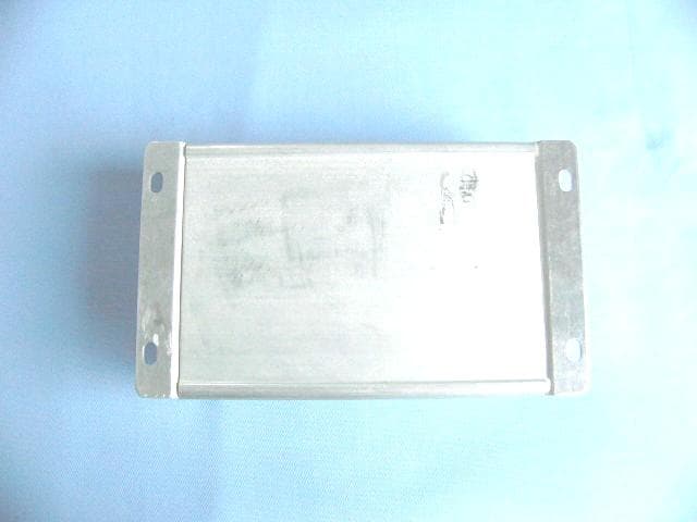
P3CSIM200
Mar 15, 2007GPRS VEHICLE TERMINAL
Equipment Class
PCB - PCS Licensed Transmitter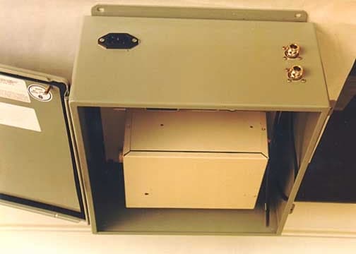
P3CUT0151
Jan 13, 2002Data Terminal (TS1000UT0)
Equipment Class
JBP - Part 15 Class B Computing Device Peripheral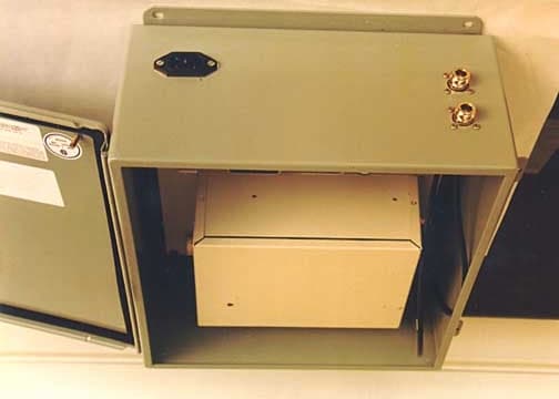
P3CBS0151
Jan 09, 2002Base Station
Equipment Class
JBC - Part 15 Class B Computing Device/Personal Computer