P3CSIM200GPRS VEHICLE TERMINAL
Wacal Inc.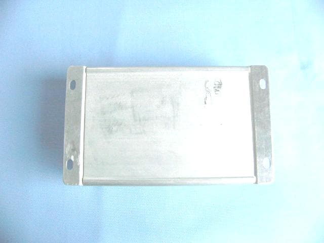
Click to zoom
Application Details
- Equipment Class
- PCB - PCS Licensed Transmitter
- Date of Grant
- Mar 15, 2007
- Application Purpose
- Original Equipment
- Date of Application
- Mar 14, 2007
- Equipment Note
- GPRS VEHICLE TERMINAL
- Frequency Range
- 1850.20000000 - 1909.80000000
- Company
- Wacal Inc.
- Country
- United States
Documents & Files
Document Text
Text extracted from the exhibit documents filed with the FCC. Open a document above to read the original.
Users Manual
INSTRUCTION FOR THE FLEET MANAGEMENT ON-VEHICLE TERMINAL P3CSIM200 is an on-vehicle terminal specially designed for the managing of commercial vehicle fleets. The terminal can transfer the GPS longitude and latitude data of vehicles to the severs of service providers in real time. The terminal works on three frequencies, 900, 1800, and 1900. Service providers can optimize the settings of the terminal according to the requirement of customers and the cost of using local GPRS networks. P3CSIM200 terminal can provide: 1. Transferring GPS data, which include: longitude and latitude information, time, speed of vehicle and driving direction. The GPS data collection interval can be preset between 10 seconds and 60 minutes. 2. At the same time of transferring GPS data, the terminal can report to the servers of the signal strength of the GPRS networks according to the preset interval. So service providers can know if the on-vehicle GPRS antenna is installed properly and working properly. 3. At the same time of transferring GPS data, the terminal can report the working temperature of its self to the service providers according to the preset interval, so service providers can know if the terminal is installed in a right location. 4. The terminal can estimate if there are any data drifting, and thus can delete most of the drifting data. 5. There is a 1m internal memory for the terminal, so all the data can be saved when there is a communication problem, when everything is back to normal, the data can be transfer to the servers. 6. The backup battery can let the terminal work for 24 hours. When the external power is cut off, the terminal can send power off alarm signals to the servers. 7. The terminal has 4 input circuits. According to the requirement of customers, service providers can transfer data, which include: if the vehicle engine is turned on or turned off, the doors are opened or closed, if the seatbelts are used, or in the case of a direct link with vehicle’s alarm system, if there is a activation of the alarm system, to the servers according to preset intervals. 8. Through 4 input circuits, the servers can command the terminal to cut off the vehicle’s electrical power supply, the fuel line, or activate the alarms, according to the customer’s demand, all above mentioned actions can be taken at the same time or one from each other. Warning FCC regulations state that: 1. The Grantee of a license has the responsibility of assuring that all equipment operated under that license confirms to the specifications of the license. 2. The RF power output of a radio transmitter shall be no more than that required for satisfactory technical operation considering the area to be covered and local conditions. 3. The frequency, deviation, and power of a radio transmitter must be maintained within specified limits. It is recommended, therefore, that these three parameters be checked before the station is placed in service. REMEMBER The efficiency of the equipment depends upon a good installation. Manufacturer recommends that adjustments to this equipment be made ONLY by a certified technician. CAUTION Changes or modifications not expressly approved by the party responsible for compliance could void the user's authority to operate the equipment. The equipment accessories are approved by FCC and only accessories from Manufacturer are qualified for this equipment applications. Detail information see FCC part 15.27. IMPORTANT (a) Only shielded cables, antennas, and special connectors from Manufacturer can be used in this system. Information detailing any alternative method used to supply the special accessories shall be must be approved by FCC and included in the application for a grant of equipment authorization or retained in the verification records, as appropriate. The party responsible for the equipment shall ensure that these special accessories are provided with the equipment. The instruction manual for such devices shall include appropriate instructions on the first page of the text concerned with the installation of the device that these special accessories must be used with the device. It is the responsibility of the user to use the needed special accessories supplied with the equipment. (b) If a device requiring special accessories is installed by or under the supervision of the party marketing the device, it is the responsibility of that party to install the equipment using the special accessories. For equipment requiring professional installation, it is not necessary for the responsible party to market the special accessories with the equipment. However, the need to use the special accessories must be detailed in the instruction manual, and it is the responsibility of the installer to provide and to install the required accessories. (c) Accessory items that can be readily obtained from multiple retail outlets are not considered to be special accessories and are not required to be marketed with the equipment. The manual included with the equipment must specify what additional components or accessories are required to be used in order to ensure compliance with this part, and it is the responsibility of the user to provide and use those components and accessories. (d) The resulting system, including any accessories or components marketed with the equipment, must comply with the regulations. IMPORTANT INFORMATION (FCC Part 15.105) This equipment has been tested and found to comply with the limits for a Class B digital device, pursuant to Part 15 of the FCC Rules. These limits are designed to provide reasonable protection against harmful interference in a residential installation. This equipment generates, uses and can radiate radio frequency energy and, if not installed and used in accordance with the instructions, may cause harmful interference to radio communications. However, there is no guarantee that interference will not occur in a particular installation. If this equipment does cause harmful inter…
Text truncated - open the document above for the full version.
Cover Letter(s)
CONFIDENTIALITY LETTER Date: Marh 7, 2007 Federal Communications Commission 7435 Oakland Mills Road Columbia, MD 21046 Gentlemen: This letter is to comply with Section 0.457(d)(2)(i) and 0.459 pertaining to confidential material. Wacal Inc would like the following documents regarding this submission for FCC ID: P3CSIM200 to be kept confidential. 1. Schematic.PDF 2. Block Diagram.PDF 3. Operational Description.PDF 4. Parts List&Tune Up Info parts list.PDF 5. Parts List&Tune Up Info tuning procedure.PDF The above material contains trade secrets or technical data, which would customarily be guarded from competitors. We do not want these documents to be accessible to the general public. Sincerely, Xilun Chen / Engineer
External Photos
EUT top view EUT bottom view
ID Label/Location Info
The Label must not be a stick-on paper label. The Label on these products must be permanently affixed to the product and readily visible at the time of purchase and must last the expected lifetime of the equipment not be readily detachable. Proposed Label Location on EUT EUT Bottom View/Proposed FCC ID Label Location FCC ID: P3CSIM200 WARNING: This device complies with Part 15 of the FCC Rules. Its operation is subject to the following conditions: (1) This device may not cause harmful interference. (2) This device must accept any received interference including interference that may cause undesired operation.
Internal Photos
EUT inside whole view Main board component side
Test Report
The test report consists 28 pages in total. It may be duplicated completely for legal use with the allowance of the applicant. It shall not be reproduced except in full, without the written approval of Ke Mei Ou Laboratory Corporation. The test result in the report only applied to the tested sample. FCC TEST REPORT Under FCC Part 24 Subpart E: 2004 Prepared For : Wacal Inc 10501 Valley Blvd., Suite 1860, E1 Monte CA91731 USA March 2, 2007 FCC ID: P3CSIM200 EUT: GPRS Vehicle Terminal Model: SIM200 Report Type: Original Report Test Engineer: Jacky Huang Test Date: February 12, 2007 Review By: Apollo Liu / Manager Ke Mei Ou Laboratory Co., Ltd. 7A, Jiaxiangge, Jiahuixincheng, No.3027, Shennan Rd., Futian, Shenzhen, Guangdong, P.R.China. Zip Code: 518033 Tel: + 86 755 83642690 Fax: + 86 755 83297077 www.kmolab.com FEDERAL COMMUNICATIONS COMMISSION Registration Number: 125782 INDUSTRY CANADA Registration Number: IC4986 Wacal Inc FCC ID: P3CSIM200 FCC ID Report Report #: KSZ2007011202J Page 2 of 28 TABLE OF CONTENTS 1. General Information..................................................................................................................................................................................................3 1. 1 Notes....................................................................................................................................................................................................................3 1. 2 Testing Laboratory...............................................................................................................................................................................................3 1. 3 Details of Applicant..............................................................................................................................................................................................3 1. 4 Application Details...............................................................................................................................................................................................3 1. 5 Test Item...............................................................................................................................................................................................................3 1. 6 Test Standards......................................................................................................................................................................................................3 2. Technical Test Results................................................................................................................................................................................................4 2. 1 Summary of Test Results......................................................................................................................................................................................4 2. 2 EUT Modifications...............................................................................................................................................................................................4 3. Technical Characteristics Test...................................................................................................................................................................................5 3. 1 Conducted Emission Test.....................................................................................................................................................................................5 3.1.1 Test Equipment...................................................................................................................................................................................................5 3.1.2 Test Procedure....................................................................................................................................................................................................5 3.1.3 Test Setup...........................................................................................................................................................................................................5 3.1.4 Configuration of the EUT...................................................................................................................................................................................6 3.1.5 EUT Operating Condition..................................................................................................................................................................................6 3.1.6 Conducted Power Line Emission Limits............................................................................................................................................................6 3.1.7 Conducted Power Line Test Result.....................................................................................................................................................................6 3. 2 RF Output Power..................................................................................................................................................................................................7 3.2.1 Test Equipment...................................................................................................................................................................................................7 3.2.2 Test Procedure....................................................................................................................................................................................................7 3.2.3 Test Setup...........................................................................................................................................................................................................7 3.2.4 Configurat…
Text truncated - open the document above for the full version.
Test Setup Photos
Radiated emission test view
Contact Information
Applicant
Weiping Zheng(Chief Executive Officer)
Test Firm
Shenzhen Academy of Metrology & Quality InspectionPeter Lin
Technical Specifications
| # | Rule Parts | Frequency Range | Power Output | Emission | Tolerance |
|---|---|---|---|---|---|
| 1 | 24E | 1.85 GHz - 1.91 GHz | 1 W | 300KGXW | 2.5000000000 ppm |
Other Applications from Wacal Inc.
P3CSIM100
Jan 29, 2006GPRS Modular
Equipment Class
PCB - PCS Licensed Transmitter
P3CUT0151
Jan 13, 2002Data Terminal (TS1000UT0)
Equipment Class
JBP - Part 15 Class B Computing Device Peripheral
P3CBS0151
Jan 09, 2002Base Station
Equipment Class
JBC - Part 15 Class B Computing Device/Personal Computer