P3CUT0151Data Terminal (TS1000UT0)
Wacal Inc.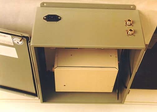
Click to zoom
Application Details
- Equipment Class
- JBP - Part 15 Class B Computing Device Peripheral
- Date of Grant
- Jan 13, 2002
- Application Purpose
- Original Equipment
- Date of Application
- Dec 11, 2001
- Equipment Note
- Data Terminal (TS1000UT0)
- Company
- Wacal Inc.
- Country
- United States
Documents & Files
Document Text
Text extracted from the exhibit documents filed with the FCC. Open a document above to read the original.
Users Manual
TS1000BS Base Station User’s Menu Revision 2.0 TS1000BS Base Station User Menu 2 Copyright 2000 Telstar Telecom Inc. All right reserved is registered trademarks of Telstar Telecom Inc. Other products and service mentioned in this document are identified by the trademarks or service marks of their respective companies or organizations. No part of this publication, or any software included with it, may be reproduced, stored in a retrieval system, or transmitted in any form or by any means, including photocopying, electronic, mechanical, recording or otherwise, without the prior written permission of the copyright holder. Telstar Telecom Inc. provides this document as is, without warranty of any kind either expressed or implied including, but not limited to, the implied warranties of merchantability and fitness for a particular purpose. Telstar Telecom Inc. may take changes of improvements in the equipment, software, or specifications described in this document at any time and without notice. These changes may be incorporated in new releases of this document. This document may contain technical inaccuracies or typographical errors, Telstar Telecom Inc. waives responsibility for any labor, materials, or costs incurred by any person or party as a result of using this document. Telstar Telecom Inc. shall not be liable for any damages (including, but not limited to, consequential, indirect or incidental, special damages, or loss of profits or data) even if they were foreseeable and Telstar Telecom Inc. has been informed of their potential occurrence arising out of or in connection with this document or its use. Computer Software Copyrights The Telstar Telecom products described in this manual include copyright Telstar Telecom computer programs stored in computer memories or other media. Laws in the United States and other countries preserve for Telstar Telecom certain rights for copyright computer programs, including the exclusive right to copy or reproduce in any form the copyrighted computer program. Accordingly, any copyrighted Telstar Telecom computer programs contained in the Telstar Telecom products described in this manual may not be copied without the express written permission of Telstar Telecom Inc. Telstar Telecom Inc. 10423 Valley Blvd, Suite D El Monte, CA 91731, U. S. A. http://www.telstartelecom.net TS1000BS Base Station User Menu 3 Contents: 1.OVERVIEW............................................................................................................................... 4 2.STATION OPERATION .......................................................................................................... 6 2.1 STATION ELEMENTS ............................................................................................................. 6 2.1.1 CABINET ............................................................................................................................ 6 2.1.2 CONTROL CIRCUIT..........................................................................................................7 2.1.3 OPTIONAL TRANSCEIVER............................................................................................... 7 2.1.4 AC POWER SUPPLY..........................................................................................................7 2.1.5 SOLAR SUPPLY ................................................................................................................. 8 2.2 OPERATION.............................................................................................................................. 9 2.3 STATION DIAGNOSTICS ..................................................................................................... 10 2.3.1 POWER_UP/RESET DIAGNOSTICS............................................................................... 11 2.3.2 CONTINUOUS DIANGONSTICS .................................................................................... 11 3. INSTALLATION .......................................................................................................................... 12 3.1 FCC REQUIREMENTS...........................................................................................................12 3.2 INSPECTION........................................................................................................................... 16 3.3 PLANNING THE INSTALLATION....................................................................................... 16 3.4 INSTALLATION ..................................................................................................................... 16 4. LIGHTING PROTECTION RECOMMENDATIONS............................................................. 18 4.1 GENERAL................................................................................................................................ 18 4.2 INSTALLATION INSTRUCTIONS ....................................................................................... 18 5. MAINTENANCE .......................................................................................................................... 20 TS1000BS Base Station User Menu 4 1. OVERVIEW Telstar’s line of TS1000BS base stations and repeaters are versatile enough to allow for a variety of communications applications, and flexible enough to accommodate future requirements. The standard stations are available in a full range of RF bands and power levels. A host of operations may be added to the station to further expand its capabilities. For the most part, these options are accomplished in software to minimize hardware changes. The TS1000BS station is a microprocessor-controlled station. Its standard features are listed as: • Data packet transmission and receiving • Optional RF transceiver for different bands • Capable of 115,200 Baud Data transmission • Extensive self diagnostics • Solid-state, easily serviceable, modular design • RF shielding and filtering to meet FCC Industrial Class…
Text truncated - open the document above for the full version.
Block Diagram
Description of the TS1000BS base station circuit The TS1000BS base station is embedded with a CPU MC68332, EPROM 27C256, SRAM 43256, IC ST16C2552, RS232 driver MAX3238, and LED indicators. Digital circuit runs with 14.7456MHz clock. Data from one port among J0, J1, and J2 is processed and distributed into other ports. TS1000BS also provides an interface port for wireless transceiver that is integrated by a user. Circuit Block Diagram CPU MC68332 SR AM EPROM EEPROM Debug Port Clock 14.7456MHz RS232 Drive IC Expand Serial I/OLED Indicators DC Regulator Reset Circuit 1.8432MHz
Cover Letter(s)
TELSTAR TELECOM INC. WWW.TELSTARTELECOM.NET 10423 Valley Blvd, Suite D, El Monte, CA 91731 Tel: 626-433-0451 FAX: 626-433-0461 January 14, 2002 Federal Communications Commission 7435 Oakland Mills Road Columbia, MD 21046 Gentlemen: This letter is to comply with Section 0.457(d)(2)(i) pertaining to confidential material. Telstar Telecom Inc. would like the following documents regarding this submission for FCC ID: P3CBS0151 to be kept confidential. 1. Pages 1 of 1 of Schematics_BS.doc The above material contains trade secrets or technical data, which would customarily be guarded from competitors. We do not want these documents to be accessible to the general public. Sincerely, Weiping Zheng, Ph.D. Chief Executive Officer Telstar Te lecom Inc.
ID Label/Location Info
FCC Label Placement on TS1000BS Base Station FCC Label
ID Label/Location Info
FCC label sample: Model Number: TS1000BS0 Serial Number: B0100001 FCC ID: P3CBS0151 Telstar Telecom Inc. El Monte, CA 91731 This device complies with Part 15 of the FCC Rules. Operation is subject to the following two conditions: (1) this device ma y not ca use har mful interference, and (2) this device must accept any interference received, including interference that may cause undesired operation. (3) FCC ID: KNY- 209228624168 inside device
Operational Description
Description of the TS1000BS base station circuit The TS1000BS base station is embedded with a CPU MC68332, EPROM 27C256, SRAM 43256, IC ST16C2552, RS232 driver MAX3238, and LED indicators. Digital circuit runs with 14.7456MHz clock. Data from one port among J0, J1, and J2 is processed and distributed into other ports. TS1000BS also provides an interface port for wireless transceiver that is integrated by a user. Circuit Block Diagram CPU MC68332 SR AM EPROM EEPROM Debug PortClock RS232 Drive IC Expand Serial I/OLED Indicators DC Regulator Reset Circuit
Test Report
Page 1 of 39 Report No.: FC01-081 TELSTAR TELECOM INC. TEST REPORT FOR THE BASE STATION (TS1000BS0) AND WIRELESS DATA TERMINAL (TS1000UT0) FCC PART 15 SUBPART B SECTIONS 15.107 & 15.109 COMPLIANCE DATE OF ISSUE: NOVEMBER 27, 2001 PREPARED FOR: Telstar Telecom Inc. 10423 Valley Blvd., Suite D El Monte, CA 91731 PREPARED BY: Joyce Walker CKC Laboratories, Inc. 5473A Clouds Rest Mariposa, CA 95338 W.O. No.: 77927 Date of test: October 30 - November 1, 2001 Report No.: FC01-081 This report contains a total of 39 pages and may be reproduced in full only. Partial reproduction may only be done with the written consent of CKC Laboratories, Inc. Page 2 of 39 Report No.: FC01-081 TABLE OF CONTENTS Administrative Information ............................................................................................. 4 Summary of Results......................................................................................................... 5 Required EUT Changes To Comply................................................................................ 5 Approvals......................................................................................................................... 5 Equipment Under Test (EUT) Description...................................................................... 6 Equipment Under Test..................................................................................................... 6 Peripheral Devices ........................................................................................................... 6 Specifications and Requirements..................................................................................... 7 Report of Measurements.................................................................................................. 8 Table 1: Six Highest Radiated Emission Levels - Base Station : 30-1000 MHz......... 8 Table 2: Six Highest Conducted Emission Levels – Base Station: 450 kHz- 30MHz .9 Table 3: Six Highest Radiated Emission Levels - Data Terminal: 30-1000 MHz....... 10 Measurement Uncertainty................................................................................................ 11 Testing ............................................................................................................................. 11 Emissions......................................................................................................................... 11 Correction Factors ............................................................................................... 12 Table A: Sample Calculations ................................................................. 12 Test Instrumentation and Analyzer Settings........................................................ 12 Table B: Analyzer Bandwidth Settings Per Frequency Range................ 12 Spectrum Analyzer Detector Functions............................................................... 13 Peak ......................................................................................................... 13 Quasi-Peak............................................................................................... 13 Average.................................................................................................... 13 Radiated Emissions ............................................................................................. 13 Conducted Emissions .......................................................................................... 14 Appendix A: Information About The Equipment Under Test......................................... 15 I/O Ports............................................................................................................... 16 Crystal Oscillators ............................................................................................... 16 Printed Circuit Boards ......................................................................................... 16 Cable Information................................................................................................ 16 I/O Ports............................................................................................................... 17 Crystal Oscillators ............................................................................................... 17 Printed Circuit Boards ......................................................................................... 17 Cable Information................................................................................................ 17 Equipment Test Setup Diagram – Base Station................................................... 18 Photograph Showing Radiated Emissions – Base Station................................... 19 Photograph Showing Radiated Emissions – Base Station................................... 20 Photograph Showing Mains Conducted Emissions – Base Station..................... 21 Photograph Showing Mains Conducted Emissions – Base Station..................... 22 Equipment Test Setup Diagram - Data Terminal ................................................ 23 Page 3 of 39 Report No.: FC01-081 Photograph Showing Radiated Emissions - Data Terminal ................................ 24 Photograph Showing Radiated Emissions - Data Terminal ................................ 25 Appendix B: Test Equipment List ................................................................................... 26 Appendix C: Measurement Data Sheets .......................................................................... 27 Page 4 of 39 Report No.: FC01-081 CKC Laboratories, Inc. has received Certificates of Accreditation from the following agencies: A2LA (USA); DATech (Germany); BSMI (Taiwan); Nemko (Norway); and GOST (Russia). CKC Laboratories, Inc has received test site Registration Acceptance from the following agencies: FCC (USA); VCCI (Japan); and Industry Canada. CKC Laboratories, Inc. has received Letters of Acceptance through an MRA for the following agencies…
Text truncated - open the document above for the full version.
Test Setup Photos
EQUIPMENT TEST SETUP DIAGRAM Base Station PHOTOGRAPH SHOWING RADIATED EMISSIONS Radiated Emissions - Front View of Base Station PHOTOGRAPH SHOWING RADIATED EMISSIONS Radiated Emissions - Back View of Base Station PHOTOGRAPH SHO WING MAINS CONDUCTED EMISSIONS Mains Conducted Emissions - Front View of Base Station PHOTOGRAPH SHO WING MAINS CONDUCTED EMISSIONS Mains Conducted Emissions - Side View of Base Station
Contact Information
Applicant
Weiping Zheng(Chief Executive Officer)
Technical Contact
CKC Laboratories, Inc.Joyce Walker
[email protected]1-800-500-4362
5473A Clouds Rest · Mariposa, California · United States
Non-Technical Contact
CKC Laboratories, Inc.Joyce Walker
[email protected]1-800-500-4362
Test Firm
CKC Laboratories, Inc.Steve Behm
Technical Specifications
| # | Rule Parts | Frequency Range | Power Output |
|---|---|---|---|
| 1 | 15B | - | - |
Other Applications from Wacal Inc.
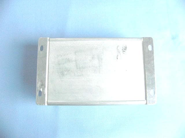
P3CSIM200
Mar 15, 2007GPRS VEHICLE TERMINAL
Equipment Class
PCB - PCS Licensed Transmitter
P3CSIM100
Jan 29, 2006GPRS Modular
Equipment Class
PCB - PCS Licensed Transmitter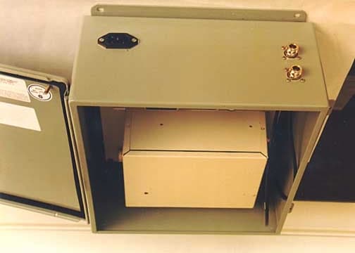
P3CBS0151
Jan 09, 2002Base Station
Equipment Class
JBC - Part 15 Class B Computing Device/Personal Computer