P3HSIRPNP3-1DIGITAL SATELLITE RADIO W/ FM- TX
Ki Ryung Electronics Co., Ltd.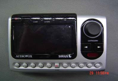
Click to zoom
Application Details
- Equipment Class
- DXX - Part 15 Low Power Communication Device Transmitter
- Date of Grant
- Aug 15, 2004
- Application Purpose
- Original Equipment
- Date of Application
- Aug 15, 2004
- Equipment Note
- DIGITAL SATELLITE RADIO W/ FM- TX
- Frequency Range
- 88.10000000 - 107.90000000
- Country
- South Korea
Documents & Files
Document Text
Text extracted from the exhibit documents filed with the FCC. Open a document above to read the original.
Users Manual
Audiovox SIR-PnP3 Draft manual JUN. 15, 2004 Note: THE MANUFACTURER IS NOT RESPONSIBLE FOR ANY RADIO OR TV INTERFERENCE CAUSED BY UNAUTHORIZED MODIFICATIONS TO THIS EQUIPMENT. SUCH MODIFICATIONS COULD VOID THE USER'S AUTHORITY TO OPERATE THE EQUIPMENT. 3-DIGIT STREAM NUMBER 8-CHARACTER CATEGORY NAME AUTO SIZING/SCROLLING SONG TITLE AUTO SIZING/SCROLLING ARTIST NAME STREAM NAME BAND/PRESET BANK NUMBER CLOCK SIGNAL STRENGTH INDICATOR Default LCD Display Front Button description Channel up/down Encoder Knob and Select Button: The Channel up/down encoder knob is the primary control for navigating through the various lists and option menus available on the unit. In the default mode, the Channel up/down knob provides sequential tuning through the available program streams. Turning Channel knob clockwise is tunes up one stream- per-detent, while turning Channel knob counterclockwise is tunes down one stream-per-detent. When in the list mode, turning knob is scrolls down and up, respectively, through the various menus and lists. The current selection from the list will be highlighted on the display. When the item is highlighted, press the Select Button to enter the selection. Pressing and holding the Select button will tune to the previously selected stream. Category Buttons: The Up or Down category buttons allows the user to advance through the stream groups based on content category. By turning Channel knob, the user can then scroll up or down through the streams within that category. Once a choice has been made, it can be entered by pressing the Select Button. Memory (MEMO) Button (S-SEEK Function): This feature allows the user to capture and store the current program data information (Stream Name & Number/ Artist & Song title). You can store up to 20 Artist/Song Title combinations. The Shuttle also has the capability to search the current incoming Sirius signal, and thereby alert you if it matches the Artist/Song title stored in Shuttle memory. Display (DISP) Button: This button allows the user to choose one of several ways of presenting the Stream Name, Artist and Song title information on the LCD screen. 2 Menu (MENU) Button: The MENU Button is used to access Menu Options which displays the user setup menu, plus other feature/ function adjustments. BAND Button (BAND)/Preset Tune (P. TUNE): Each momentary press of the BAND Button allows the user to switch between 3 bands of Stream presets (10 presets each A, B and C). Pressing and holding the BAND Button for 2 seconds initiates preset tuning that will display and tune all stored preset streams in sequence. This is indicated by the reverse image of the stream number and band preset number on the display. Pre-set tuning continues until the user decides to terminate this function by pressing and holding the BAND Button for 2 seconds. Keypad Buttons 0-9: These buttons are used to directly enter a desired stream number. They are also used when entering and recalling preset stream numbers into memory. 3 Basic Operation With the unit properly installed, activated and connected to your home or vehicle audio system, proceed as follows: 1. Press the Power button; the Shuttle turns on and the Sirius logo appears for 2 seconds followed by the default display for the stream and tuning mode in effect prior to turnoff. 2. Turn knob to select and play the desired stream, or use the Category Up/Down buttons to tune and select a desired stream based on genre. Tuning By Category When in Category Tuning Mode, each momentary press of the Category Up/Down Button(s) advances through the available Genres: 1. Using the Channel knob, select the desired stream. 2. Press the Select button to select that stream. 3. Once the stream has been selected, the unit will revert to the default screen and your selection will be played. Content Listing Options (Look Ahead) This feature allows you to view what is playing on other streams without having to change the current stream you are listening to. The content listing options are selected by using the DISP button. When the default screen is displayed on the LCD, pressing and holding the DISP Button will display all the available stream numbers and stream names. The second press of the DISP button will display all currently available artists. The third press of the DISP button will display song titles. While in the Category List menu, pressing the DISP button changes Stream List to Artist List. The available content listing now displays information by the Artist Name. The DISP button is also used during category tuning. Consecutively pressing the DISP button while tuning by category will display the Stream Name, Artist Name or Song Title within the selected category. While the preceding screens are displayed, turning Channel knob allows navigation through the list. When the desired selection is highlighted, press the Select button and your selection will be played. Direct Tuning Streams can also be directly accessed by pressing the Select (remote control)button and using the 1-6 number keys to numerically enter the desired stream. Once the desired stream number has been entered, press the Select button again to play. 4 Setting/Using Stream Preset Buttons The unit contains 10 preset buttons. There are three banks of preset memory locations offering a total of 30 presets. These banks are designated A, B and C and can be selected using the BAND button. The display in the lower right hand side changes to show the corresponding Preset bank. Each bank will store 10 user-preferred streams. Select the desired stream you wish to save into memory by using the Channel knob, the direct tuning method or the category tuning method. With the desired stream playing, press and hold any of the numbered keypad buttons or remote control buttons (0-9); the corresponding preset number will flash. A confirmation tone is heard, confirming that the preset has been stored. Continue this procedure for storing all desired streams. To retrieve a preset str…
Text truncated - open the document above for the full version.
Block Diagram
Confidential 1. System Block Diagram C O N F I DE N T I A L Confidential 2. System configuration Diagram 1. CAR System C O N F I DE N T I A L Confidential 2. System configuration (Continue) 2. Home System C O N F I DE N T I A L
Cover Letter(s)
219-6 Gasan-Dong, Kumchun-Ku Seoul, 153-023, Korea Tel : 82-2-3282-2264 Fax : 82-2-864-1675 Federal Communications Commission 7435 Oakland Mills Road Columbia, MD 21046 Gentlemen: This letter is to comply with Section 0.457(d)(2)(i) pertaining to confidential material. KI RYUNG ELECTRONICS.,CO.LTD would like the following documents regarding this submission for FCC ID: P3HSIRPNP3-1 to be kept confidential. 1. 5 Pages document schematics. 2. 3 Pages document system block diagram. The above material contains trade secrets or technical data, which would customarily be guarded from competitors. We do not want these documents to be accessible to the general public. Sincerely,
External Photos
[External Photos]
ID Label/Location Info
IDENTIFICATION LABEL: PROPOSED FCC ID LABEL The FCC ID shall be permanently affixed to the rear side of the equipment This device complies with Part 15 of the FCC Rules. Operation is subject to the following two conditions: (1) this device may not cause harmful interference, and (2) this device must accept any interference received, including interference that may cause undesired operations. Made in Korea FCC ID : P3HSIRPNP3-1
Internal Photos
[Internal Photos]
Test Report
KTL Korea Testing Laboratory Page 1 of 17 TEST REPORT Ref. Report No. 04-1341-018 This test report only responds to the tested sample and shall not be reproduced except in full without written approval of the Korea Testing Laboratory. Tested and reported by Reviewed by Name and address of the applicant KI RYUNG Electronics Co., Ltd. 219-6, Gasan-Dong, Kumchun-Ku, Seoul 153-023, Korea Standard / Test regulation FCC Part 15, Subpart C Test result Pass Incoming date : July 28, 2004 Test item(s) ; Low Power Communication Device Transmitter (Digital Satellite Radio with FM Transmitter) Model/type ref. ; SIR-PNP3 Manufacturer ; KI RYUNG Electronics Co., Ltd. Additional information ; -Required Authorization : Certification -FCC ID. : P3HSIRPNP3-1 Test date : August 6, 2004 Issue date : August 9, 2004 Jeong-Min Kim, Senior Engineer Won-Seo Cho , Telecommunication Team Manager KOREA TESTING LABORATORY FG101-01-02-00 222-13, Guro-Dong Guro-Gu Seoul Korea 152-053 http://www.ktl.re.kr Ref. Report No. 04 - 1341 – 018 Page 2 of 17 Korea Testing Laboratory Telecommunication Team 222-13, Guro3-dong, Guro-gu, Seoul Korea 152-848 TABLE OF CONTENTS I. GENERAL INFORMATION 3 1. Grantee’s Name and Mailing Address 2. Manufacturer's Name and Mailing Address 3. Equipment Descriptions 4. Rules and Regulations 5. Measuring Procedure 6. Place of Measurement 7. Date of Measurement II. GENERAL REQUIREMENTS OF THE EUT 4 1. Labeling Requirement (Section 15.19) 2. Information to User (Sections 15.21) 3. Special Accessories (Section 15.27) III. CONDUCTED EMISSION MEASUREMENT (Section 15.207) 5 1. Test Procedure 2. Photograph for the test configuration 3. Sample Calculation 4. Measurement Data IV. RADIATED EMISSION MEASUREMENT (Section 15.239 & 15.209) 9 1. Test Procedure 2. Photograph for the test configuration 3. Sample Calculation 4. Measurement Data V. OCCUPIED BANDWIDTH MEASUREMENT (Section 15.239) 14 VI. TEST EQUIPMENTS USED FOR FCC COMPLIANCE TESTING 17 Ref. Report No. 04 - 1341 – 018 Page 3 of 17 Korea Testing Laboratory Telecommunication Team 222-13, Guro3-dong, Guro-gu, Seoul Korea 152-848 I. GENERAL INFORMATION 1. Grantee’s Name and : KI RYUNG Electronics Co., Ltd. Mailing Address 219-6, Gasan-Dong, Kumchun-Ku, Seoul, 153-023, Korea 2. Manufacturer's Name and : KI RYUNG Electronics Co., Ltd. Mailing Address 219-6, Gasan-Dong, Kumchun-Ku, Seoul, 153-023, Korea 3. Equipment Descriptions 3.1 Operating Frequency : 88.1 MHz ~ 107.9 MHz 3.2 Power Supply : DC 12 V (AC/DC Adapter) 3.3 Test Configuration Device Model Manufacturer FCC ID Connected to EUT (FM Transmitter) SIR-PNP3 KI RYUNG Electronics Co., Ltd. P3HSIRPNP3-1 -- External Antenna SIRIUS SIRIUS N/A EUT AC/DC adapter DSA-0131F-12 DVE N/A EUT Speaker -- -- N/A EUT 4. Rules and Regulations : FCC Part 15, Subpart C 5. Measuring Procedure : ANSI C63.4-2001 6. Place of Measurement : Absorber-lined Room (KTL) 7. Date of Measurement 7.1 Conducted Emission : August 6, 2004 7.2 Radiated Emission : August 6, 2004 Ref. Report No. 04 - 1341 – 018 Page 4 of 17 Korea Testing Laboratory Telecommunication Team 222-13, Guro3-dong, Guro-gu, Seoul Korea 152-848 II. GENERAL REQUIREMENTS OF THE EUT 1. Labeling Requirement (Section 15.19) This device complies with Part 15 of the FCC Rules. Operation is subject to the following two conditions: (1) this device may not cause harmful interface, and (2) this device must accept any interference received, including interference that may cause undesired operation. 1.1 Location of Label : Rear side of EUT 1.2 How Applied : Printed on adhesive label 2. Information to User (Section 15.21) The following or similar statements were provided in the manual for user instruction. Please refer page 4 of the attached manual for details. CAUTION : Any changes or modifications in construction of this device which are not expressly approved by the party responsible for compliance could void the user's authority to operate the equipment. 3. Special Accessories (Section 15.27) 3.1 Were the special Accessories provided? [ ] yes, [ x ] no 3.2 If yes, details for the special accessories are as follows : 3.3 If yes, were the appropriate instructions provided on the first page of the text concerned with the installation of the device? [ ] yes, [ ] no 3.4 Are these accessories provided of the type which can be readily obtained from multiple retail outlets ? [ ] yes, [ ] no And therefore does the manual specify what additional components or accessories are required to used in order to comply with the Rules? [ ] yes, [ ] no Ref. Report No. 04 - 1341 – 018 Page 5 of 17 Korea Testing Laboratory Telecommunication Team 222-13, Guro3-dong, Guro-gu, Seoul Korea 152-848 III . CONDUCTED EMISSION MEASUREMENT (Section 15.207) 1. Test Procedure The EUT is designed to transmit on one of 99 channels in the band 88.1 to 107.9 MHz. Therefore measurements were performed with the equipment operating on three frequencies, which were the top(107.9 MHz), middle(98.1 MHz) and bottom(88.1 MHz) in the band, as per Section 15.31(m). Test mode was transmitting mode. Conducted emission measurements on the EUT were performed by "AC Power Line Conducted Emissions Testing" procedure as per ANSI C63.4. The EUT was set up on a wooden table 0.8 meters height, 1.0 by 1.5 meters in size, placed in the shielded enclosed with a side of wall of which constituted a vertical conducting surface of 2.2 m X 3.1 m in size to maintain 40 cm from the rear of EUT LISN (Line Impedance Stabilization Network, R & S, ESH3-Z5, 50 ohm/50 uH) was installed and electrically boned to the conducting ground plane. The EUT was connected to the LISN. The frequency range from 150 kHz to 30 MHz was examined and the peak values that are within 6 dB of the limit would be compared to quasi-peak values using the Quasi-Peak mode. The position of connecting cables of the EUT was changed to find the worst case configuration during measurements. The maximum emission level from the EUT occurred in such configuration as shown in the …
Text truncated - open the document above for the full version.
Test Setup Photos
[Test Setup Photos]
Contact Information
Applicant
Won-Kyu Choi(Assistant Manager)
Test Firm
Korea Testing LaboratoryJeong-Min Kim
Technical Specifications
| # | Rule Parts | Frequency Range | Power Output |
|---|---|---|---|
| 1 | 15C | 88.1 MHz - 107.9 MHz | - |
Other Applications from Ki Ryung Electronics Co., Ltd.
P3HSP5
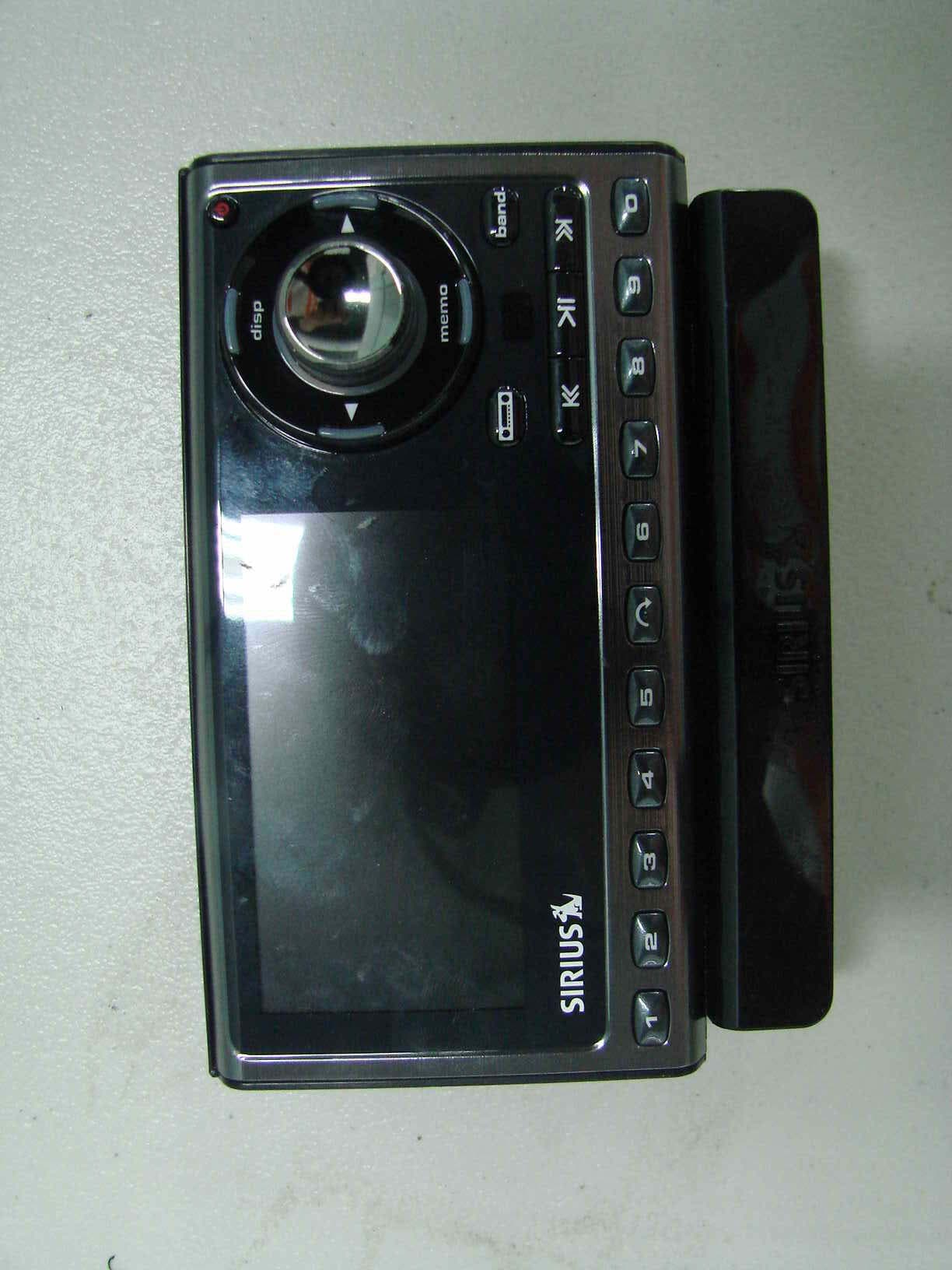
Sep 10, 2007Digital Satellite Radio
Equipment Class
DXX - Part 15 Low Power Communication Device Transmitter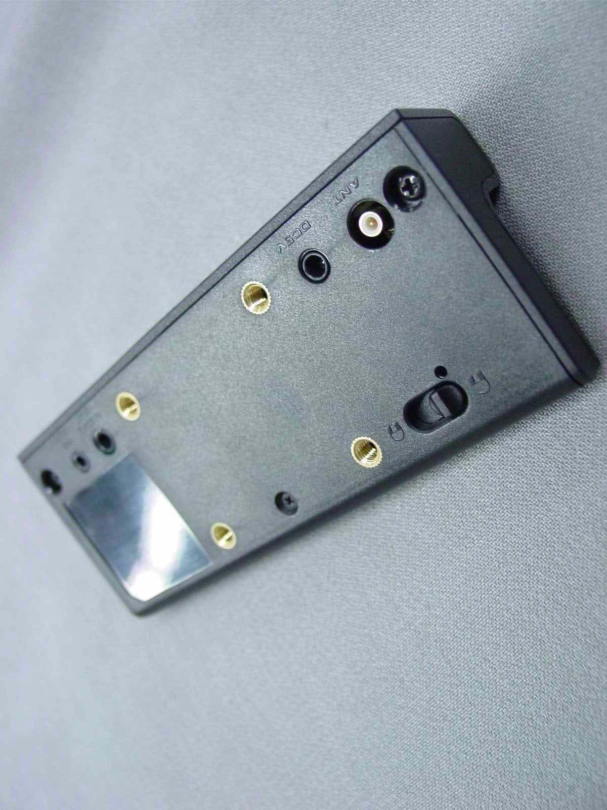
P3HSP3C
Nov 02, 2006Digital Satellite Radio w/ FM Transmitter
Equipment Class
DXX - Part 15 Low Power Communication Device Transmitter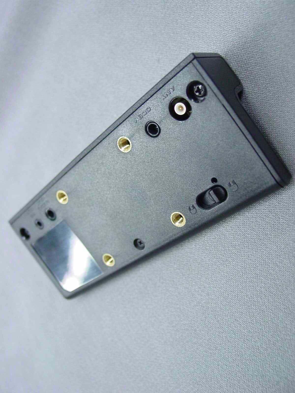
P3HSP4C
Nov 02, 2006Digital Satellite Radio w/ FM Transmitter
Equipment Class
DXX - Part 15 Low Power Communication Device Transmitter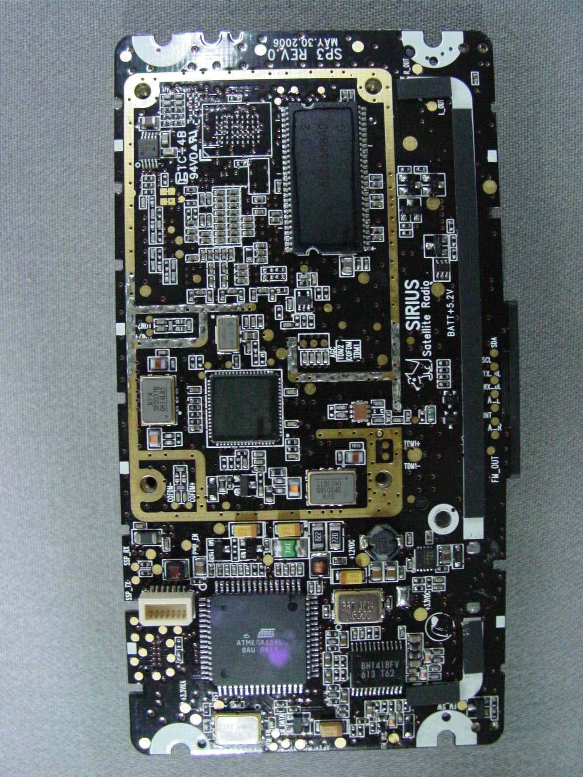
P3HNSPH-3
Oct 19, 2006Digital Satellite Radio w/FM Transmitter
Equipment Class
DXX - Part 15 Low Power Communication Device Transmitter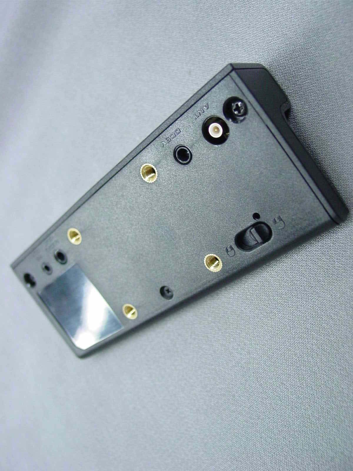
P3HNSPH4
Oct 10, 2006Digital Satellite Radio
Equipment Class
DXX - Part 15 Low Power Communication Device Transmitter